

Week 11 Output Devices
This week we will try output devices.My Gino board doesn't have a lot of pins, so I will also use arduino UNO for output devices.
Weekly Assignment
- Individule assignment: Add an output device to a microcontroller board you’ve designed and program it to do something.
- Group Assignment: measure the power consumption of an output device. 、
Output Device LCD:
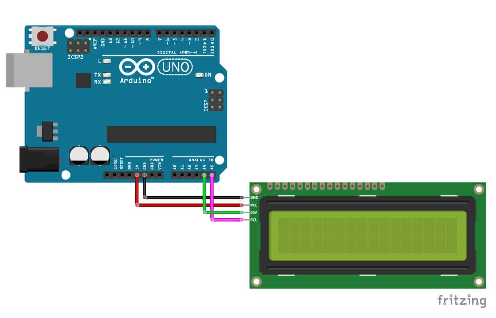
This type of LCD is ideal for displaying text and numbers, hence the name ‘character LCD’. The I2C LCD comes with a small add-on circuit mounted on the back of the module. This module features a PCF8574 chip (for I2C communication) and a potentiometer to adjust the LED backlight. The advantage of an I2C LCD is that the wiring is very simple. You only need two data pins to control the LCD.
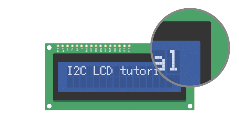
If you look closely at the LCD, you can see the small rectangles that form the individual characters of the LCD. Each rectangle is made up of a grid of 5×8 pixels. Later in this tutorial
- The SDA pin is the 12C data and that is connected to Arduino UNO analog pin, I chose A4;
- The SCL pin is the 12C clock , I chose A5 on Arduino UNO;
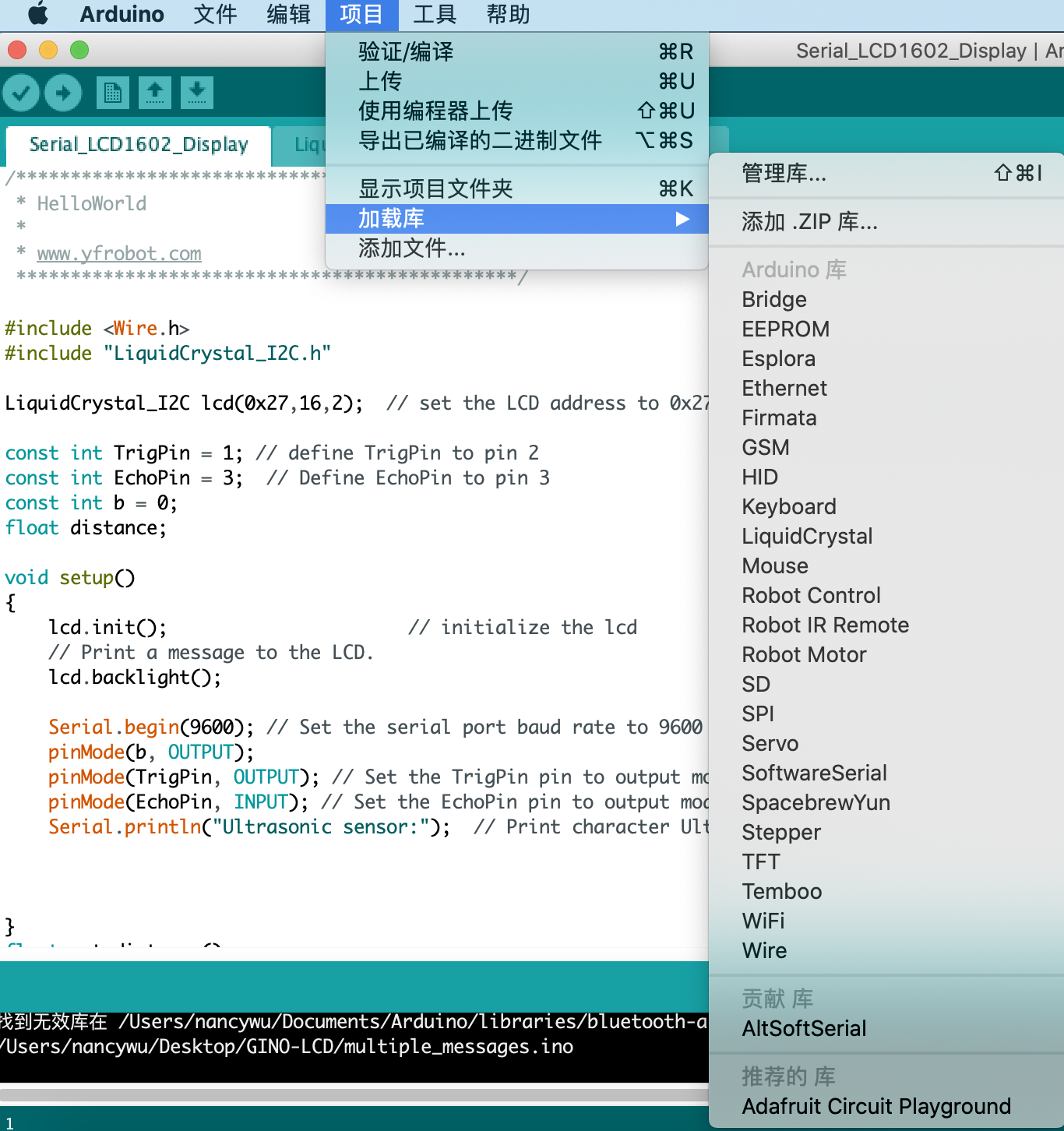
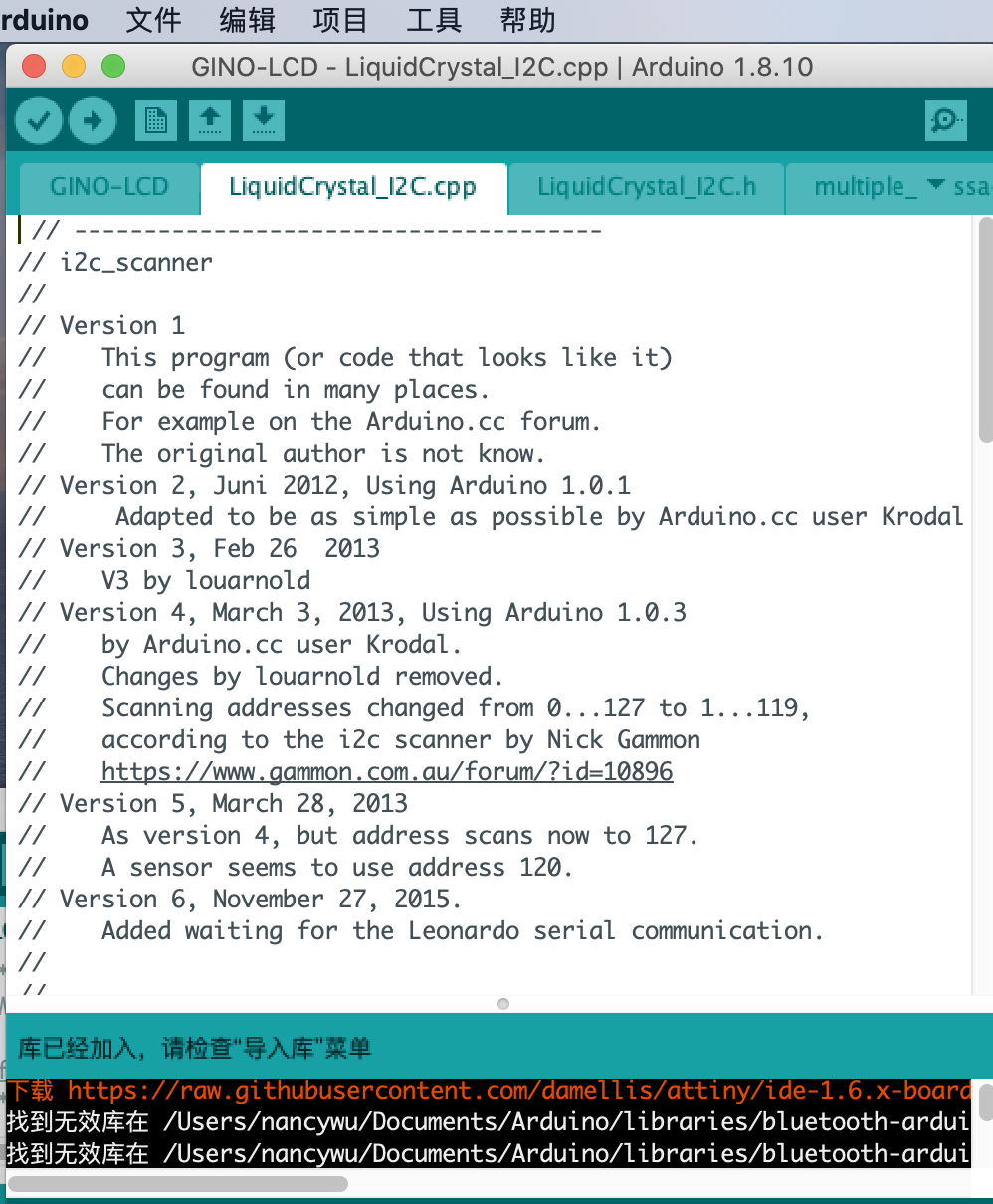
Installing the LiquidCrystal_12C Arduino Library.
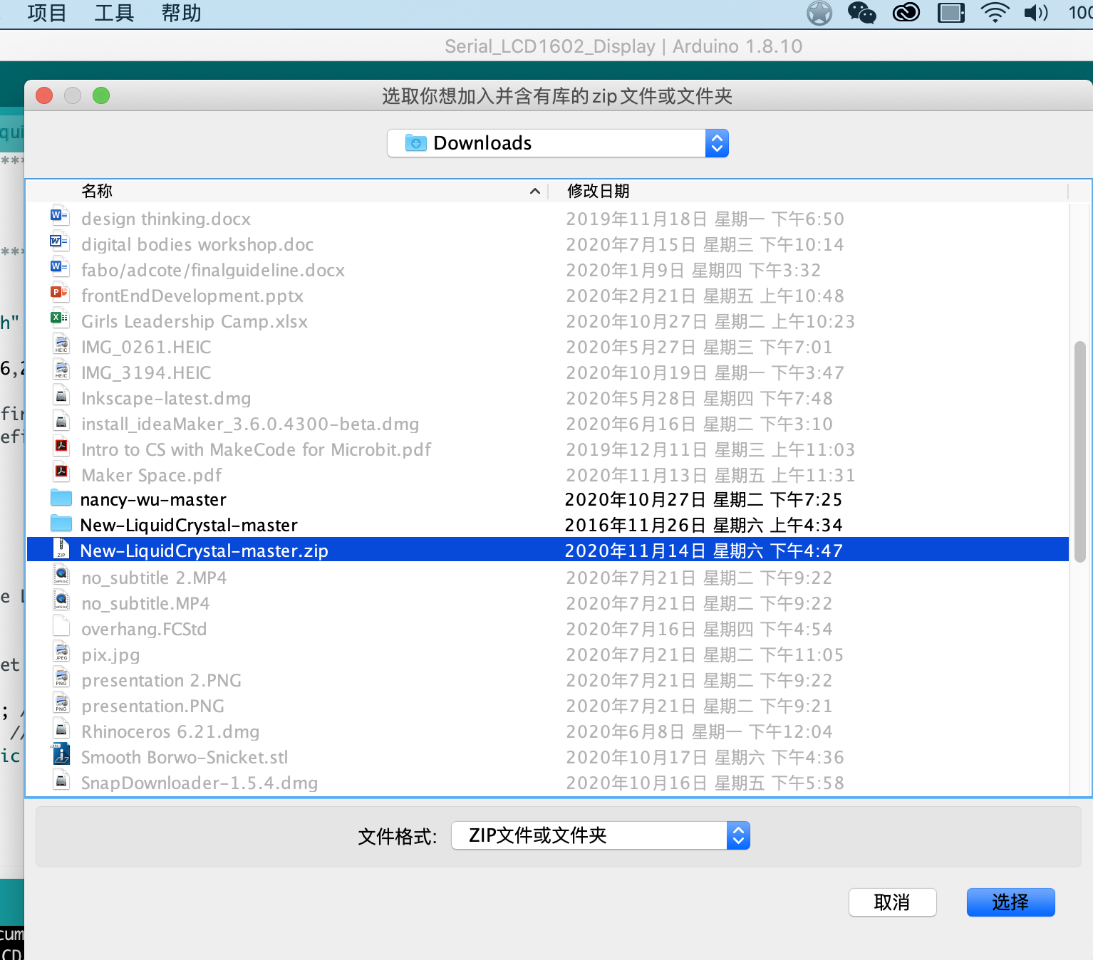
Download the LiquidCrystal_12C Arduino Library and extract the zip file
The LiquidCrystal_I2C library works in combination with the Wire.h library which allows you to communicate with I2C devices. This library comes pre-installed with the Arduino IDE.
To install this library, go to Tools > Manage Libraries in the Arduino IDE. The Library Manager will open and update the list of installed libraries.
Then search for ‘liquidcrystal_i2c’ and look for the library . Select the latest version and then click Instal
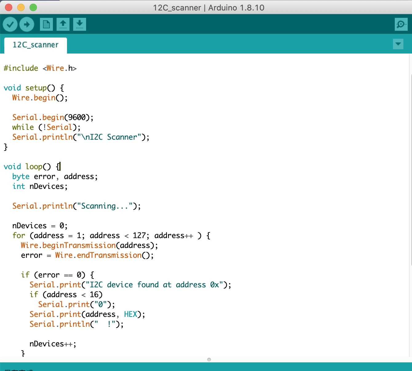
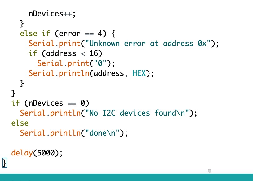
Find the I2C address of th LCD : Most I2C LCDs ship with the default address ‘0x27’, but it can be different depending on the batch/manufacturer. If this is the case, you will need to find the actual address of the LCD before you can start using it.
On the Arduino website, you can find a simple example sketch that scans the I2C-bus for devices. If a device is found, it will display the address in the serial monitor. You can copy the code by clicking on the button in the top right corner of the code field.
Gino board with Led:
I use a touch sensor as input and led as output:
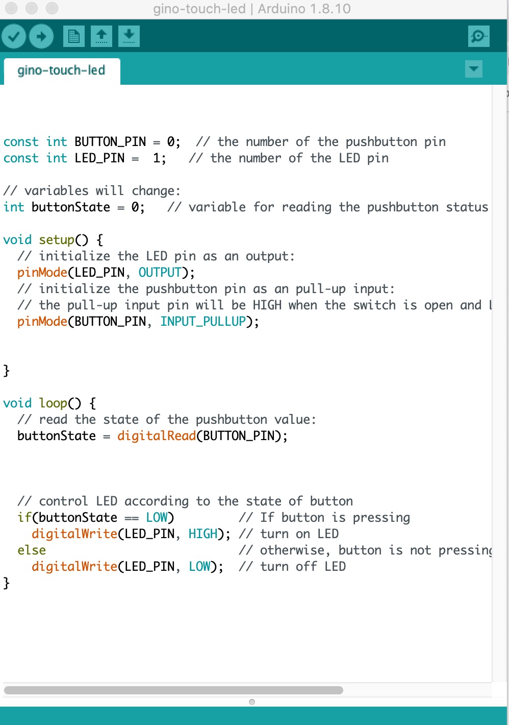
It's working well.
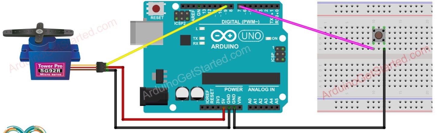
Arduino UNO Button control Motor
Connect button and servo motor to arduino.For digital module, there are two pins, one goes to numbers, the other one goes to ground; For analog modules, there are three pins, one goes to vcc(5V/3.3v), one goes to GND, one goes to analog pin (numbers with wave.)
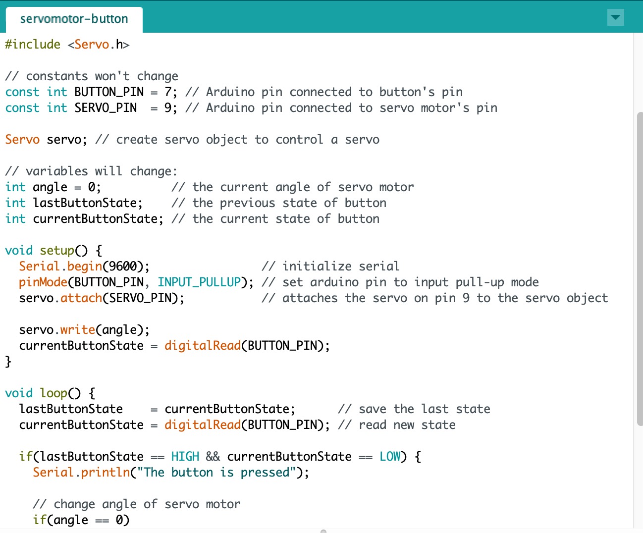
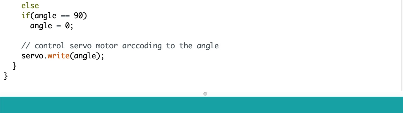
The code is below:
Video:
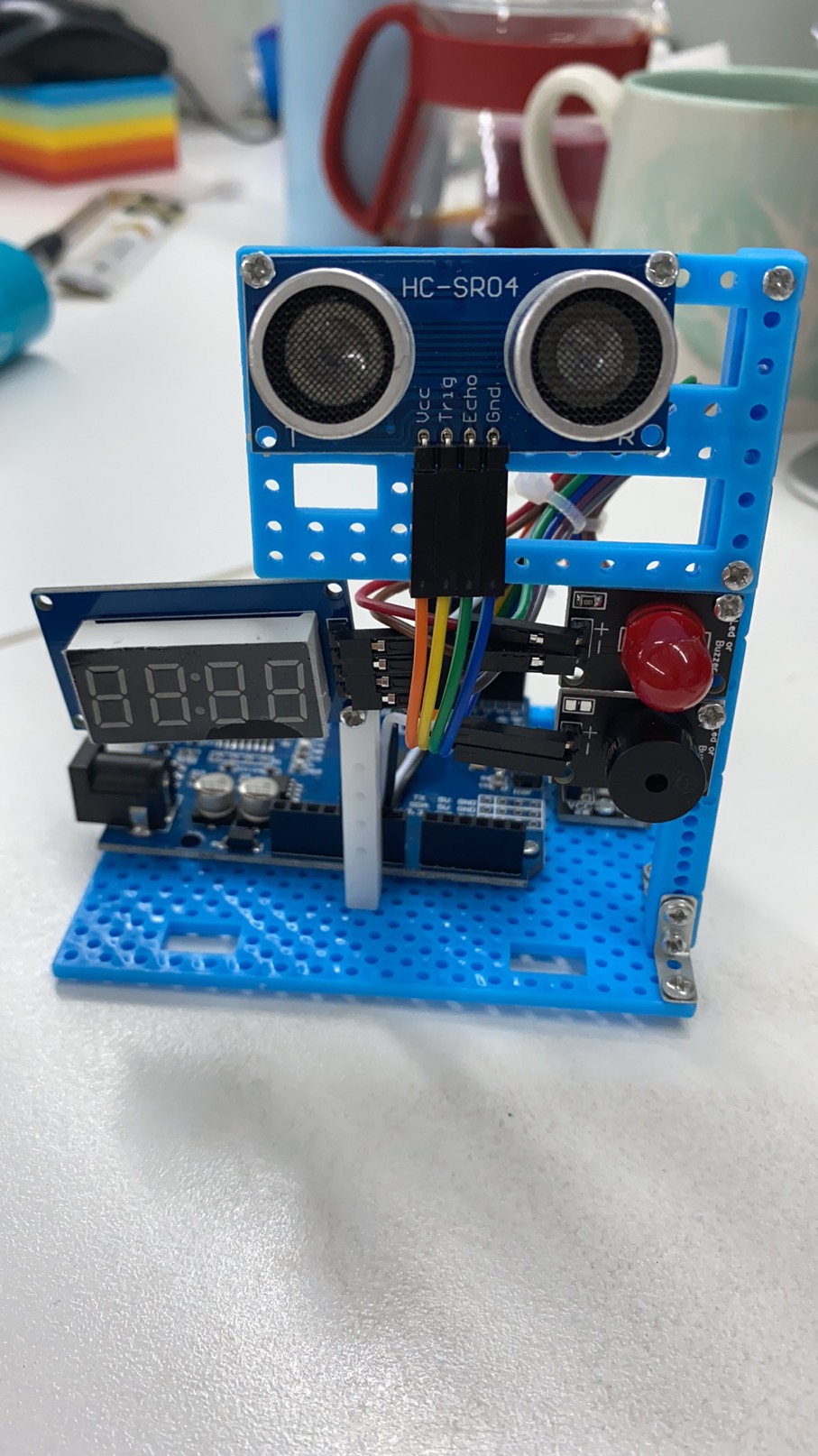
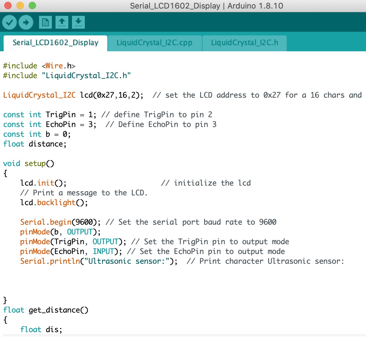
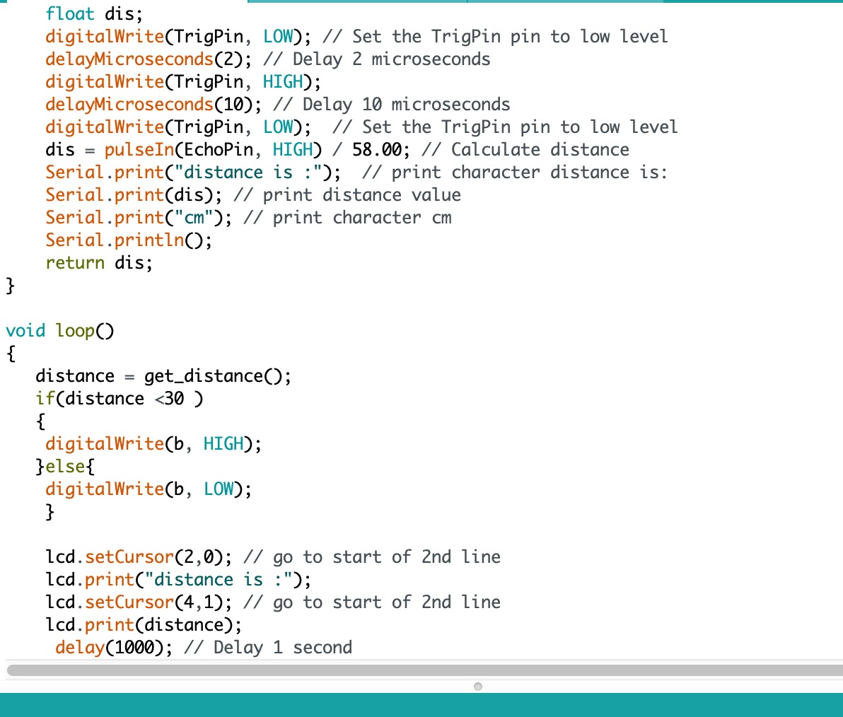
Arduino Nano Radar project:
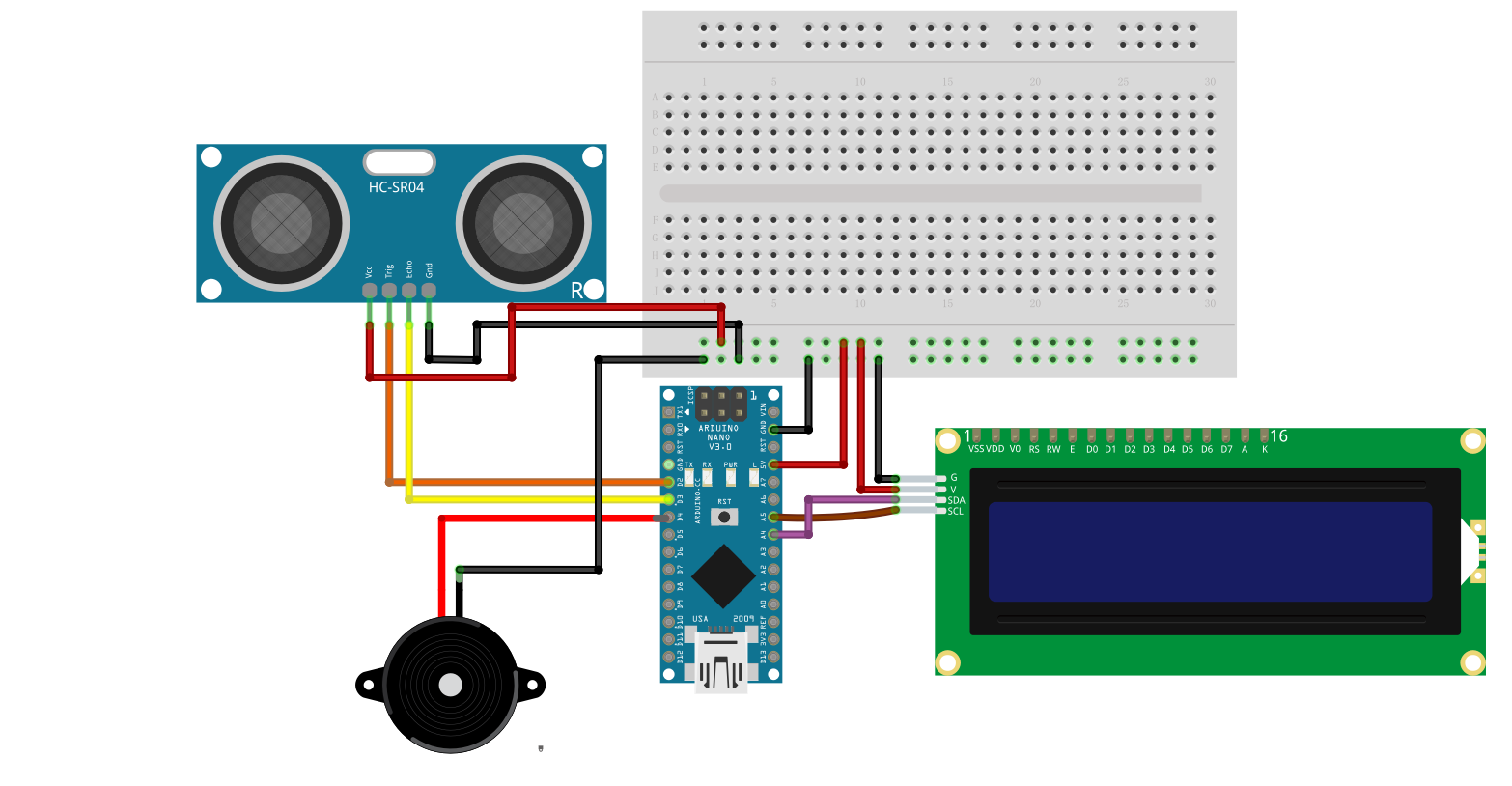
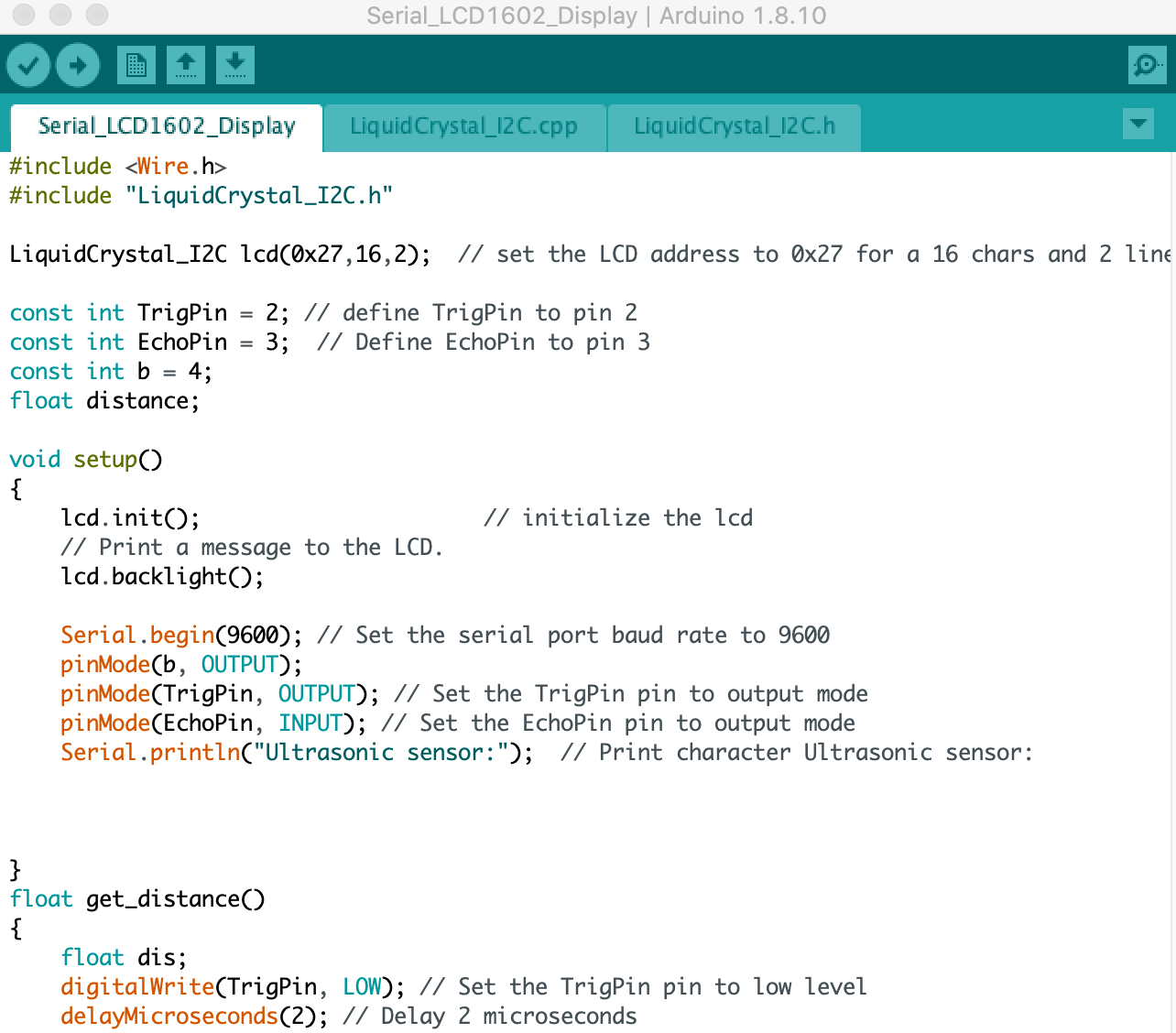
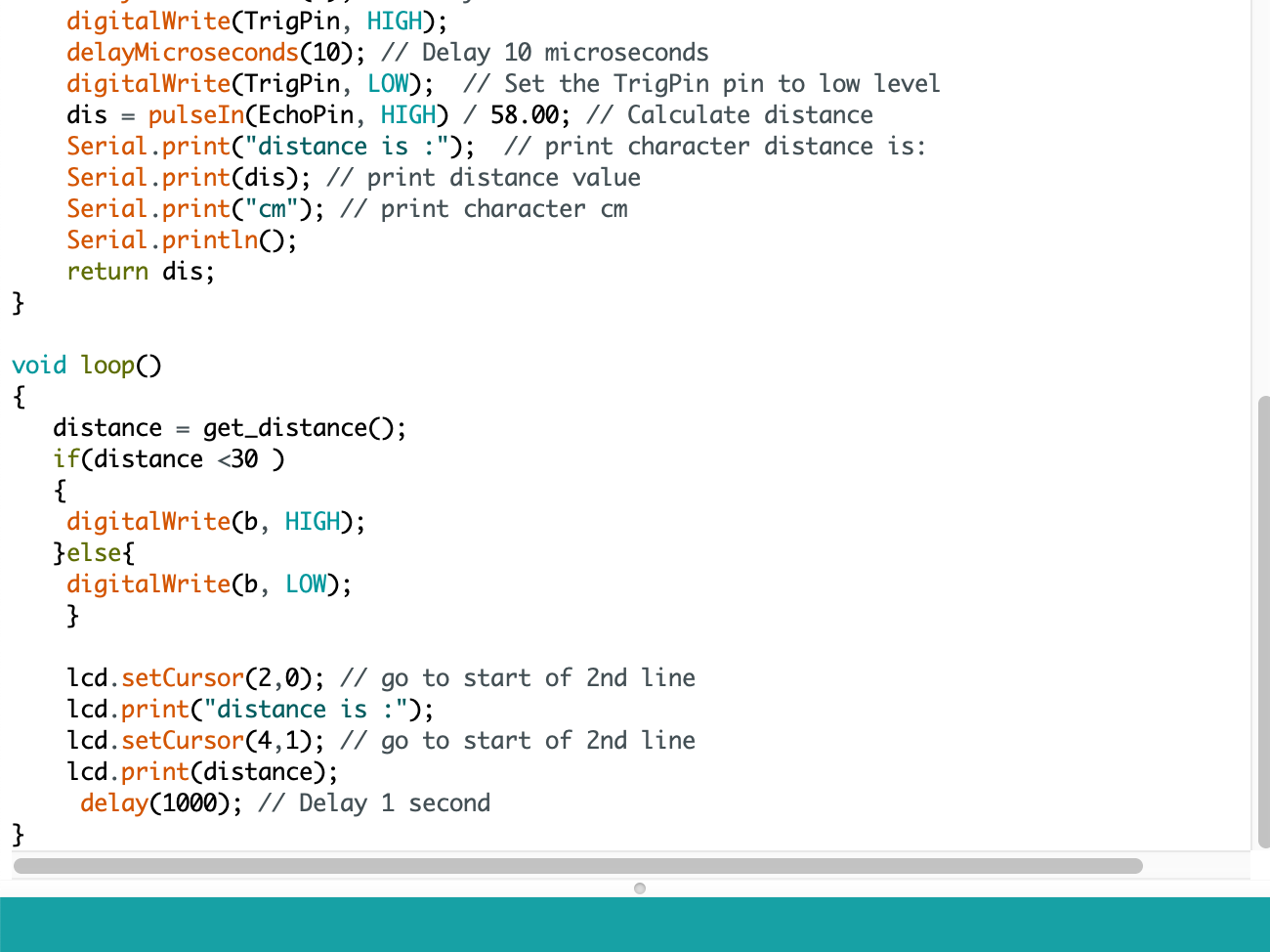
The code is below:
Download the Code for this week