Week4
Electronics production
Electronics production
Characterize the design rules for your PCB production process
Making an in-circuit programmer by milling and stuffing the PCB, test it, then optionally try other PCB processes.
First I should understand some things. What is ISP, what are the Fuses /Fuses -中文 and what is Bootloader as well as waht is FTDI?
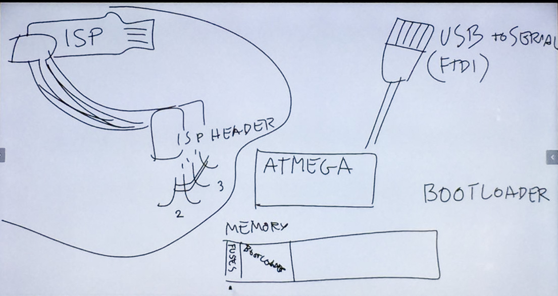
ISP :(In-System Programming)
FTDI(a company's name -英商飞特帝亚有限公司) :USB-Serial.
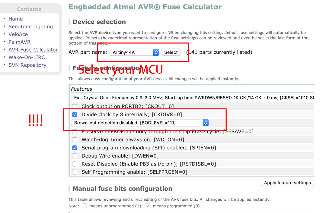
Fuses:There are 3 bytes of permanent storage in the chip called 'fuse low byte', 'fuse high byte' and 'fuse extended byte'. These bytes are called fuses and can be reprogrammed as many times as you want and determines the behaviour of the chip. To do that, their value is not erased when the chip is powered off or reprogrammed. Each microchip has its own definition for the values that must have the fuses. In this tutorial, we are going to work with the fuses of the Atmel Attiny44A.
First of all, we should known what is FABISP: This basically started out as a 100% fab-able version of the vusbtiny programmer from simpleavr with a few minor additions, namely a switch and indicator LED for target-power and a LED on the SCK line (just like a real arduino). It was inspired by David Mellis' FabISP and Andy Bardagjy's FabISPKey although it doesn't feature any solder jumpers or zero-ohm resistors ;). I used to call it FabTinyISP, but since it has so many other uses, I have decided to change the name to FabTiny* (aka. FabTinyStar) where the asterisks symbolizes a wildcard denoting the endless possibilities. Or as Bas Withagen put it: a Fab-Tiny-Anything. If you put an ATtiny85 on it instead, then you should be able to flash it with the Micronucleus bootloader (the 45 just doesn't have enough memory for that to be realy useful, but it can be done) and it will be almost completely compatible with the LittleWire and somewhat compatible with the the DigiSpark. The earlier (now obsolete) versions had the USB lines wired differently, so for them the micronucleus bootloader had to be reconfigured. Nowadays the vanilla firmware for the vusbtiny programmer has to be adjusted instead, which was already done in the downloads below.
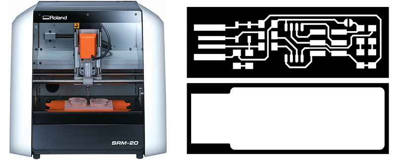
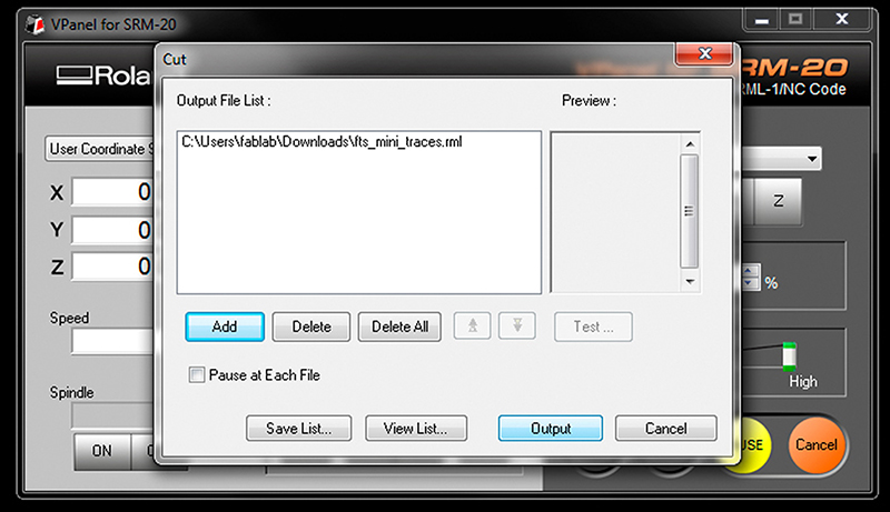
Open fab modules in my browser recommended firefox/chrome Open my traces image file (This is the one with lines that will form the wires between My components.)
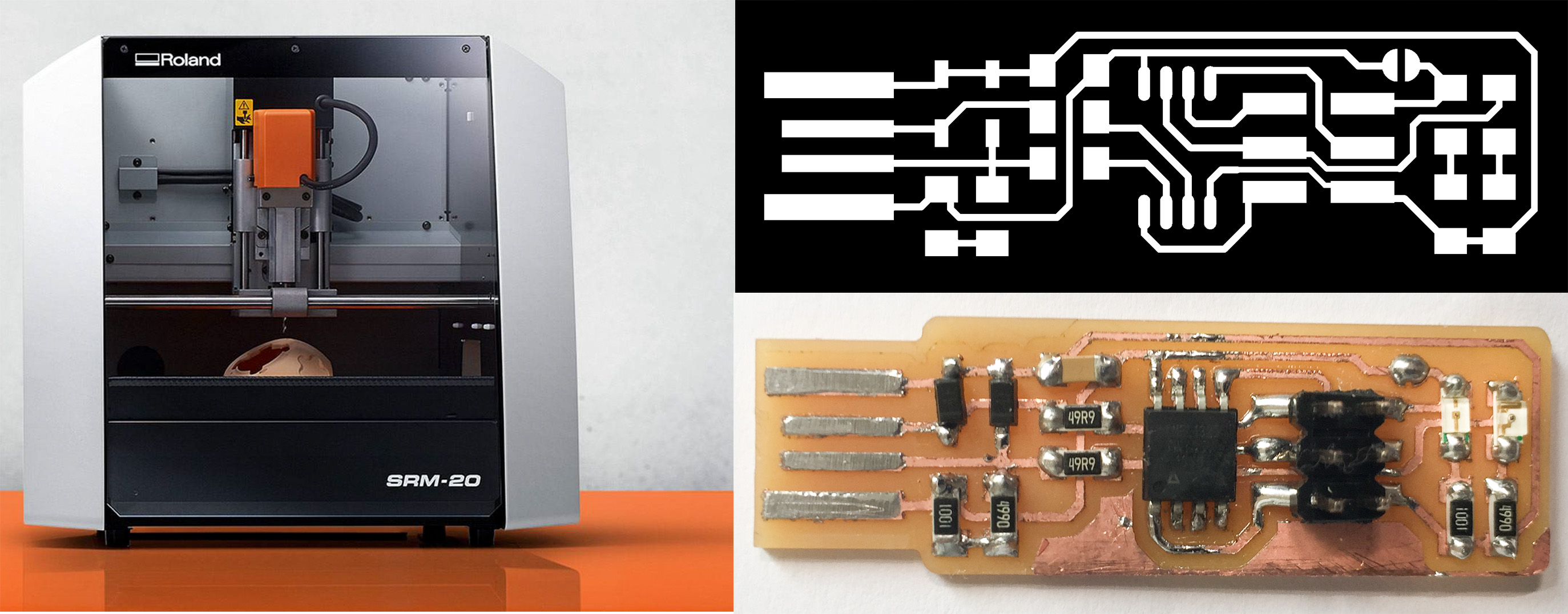
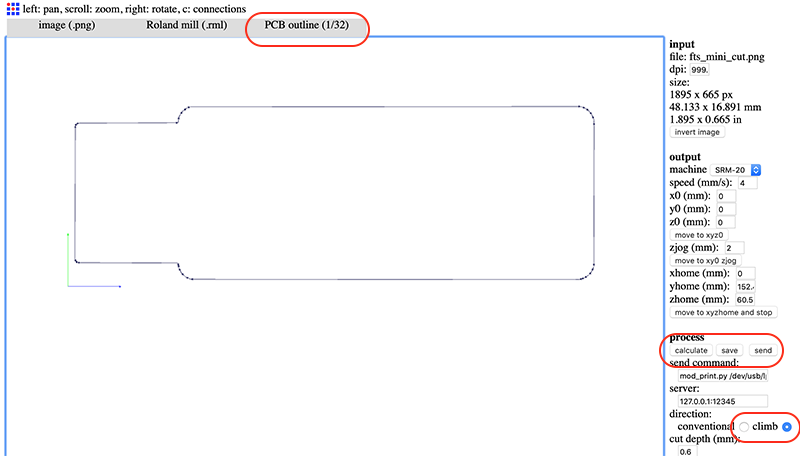
input format - PNG - select my traces image(1000 DPI) output format - roland mill (.rml) process - PCB traces (1/64)
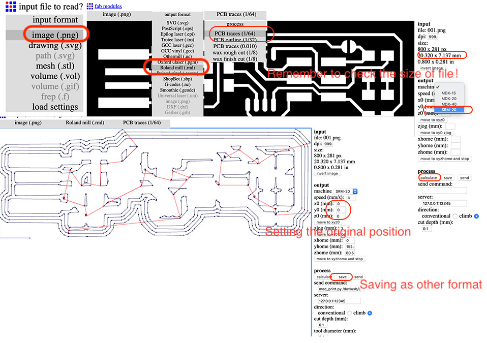
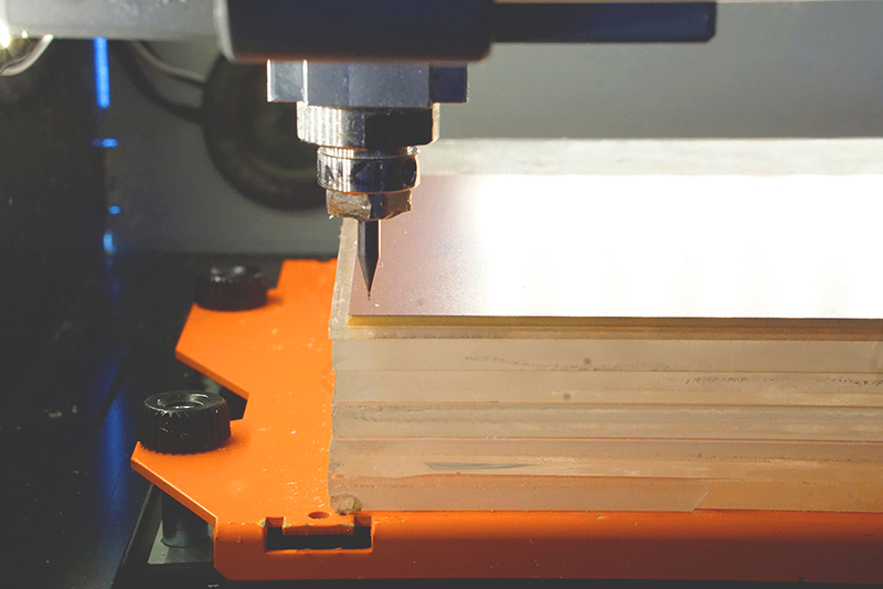
Machine - SRM-20 x0(mm) - 0 y0(mm) - 0 z0(mm) - 0 These x0,y0,z0 are for setting up an offset from the origin save in V-Panel zjopg - 2 Speed - 4 or 3 mm/s for new end mills x/y/x home is the parking position after finishing the cut
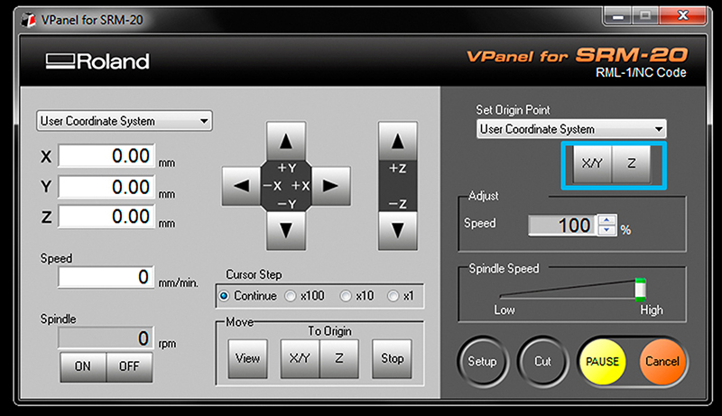
The (0,0) of your file created in fab modules is in the bottom left corner.A good starting point is just a few milimiters inside. Move the machine to its position by using the X/Y arrows in VPanel for SRM-20 Decide where to set the origin on your board.It depends on where you taped your board. When you have choosen the position click on Set origin X/Y in Vpanel
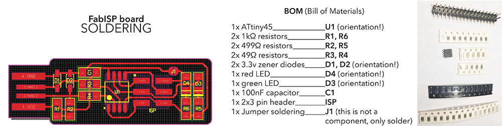
Assembling the PCB. The materials to be used with the following:
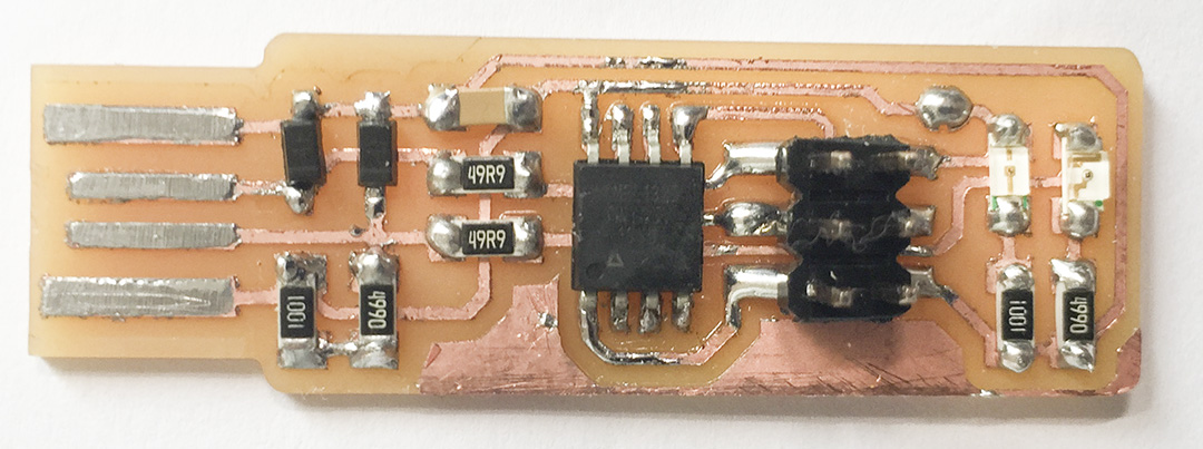
When I finished the solering, I cut down some pieces of copper using a blade and tweezer, since on the tracing file where showes some lines touching to each other and it will induce shot circuit.