At the end of last week, I was reasonably
familiar with the Part Design workflow of FreeCAD, but I still wanted to try out
some of the other features, such as technical drawings (TechDraw workbench),
assemblies (a2plus workbench) and spreadsheets (as demonstrated by Neil).
I had a project in mind for this that let me combine practice of these features with parametric design of a laser cut part: I had recently built a ‘mini’ (5" propeller) FPV Quadcopter, and had been thinking different ays to protect the blades when transporting it.
Initially I thought of a spacer that clips/snaps onto the motors bells. Here are some paper sketches of my first concept:
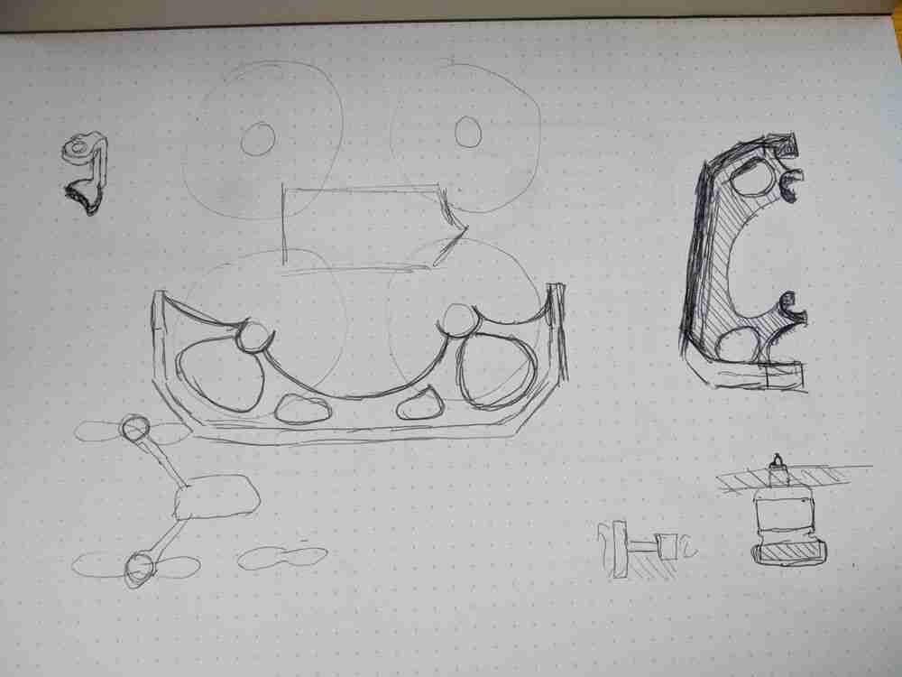
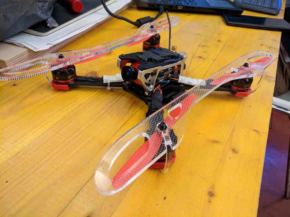
I soon realized that mounting it this way wouldn’t be able to sustain any forces parallel to the motor axis, so I came up with a different design where the protective cover is mounted directly over the propellers. The M8 hex nuts that hold the propellers on the motor shaft register in two holes in the cover. This way the cover is already arrested in all movements parallel to the frame. The load is transferred to the motors, which are soft-mounted on the drone’s carbon-fiber frame. The biggest problem with this design is that strong impacts could potentially shear the motor shafts, but given the application of this is transport of the drone in a soft backpack or wrapped in another soft material, I think it is quite reasonable.
I started by creating a Spreadsheet in FreeCAD and noted down the relevant design parameters of the Quad, as well as some material parameters (thickness and kerf):
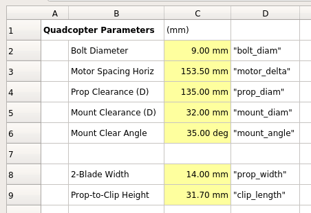
I made all parameters accessible from outside the sheet with short aliases
(right click > properties > alias), and noted the alias in a seperate column
for easy reference (this turned out to not be too important since FreeCAD auto-
completes parameter names in expressions).
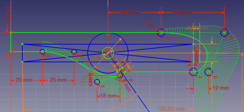
I then created a new Sketch on the XY (top) plane, and started by drawing the known parts of the drone (motor bell, rough propeller outline, motor nut) as construction lines. I only drew one of the four motors, since the design could easily be mirrored after. Then I started drawing the shape of the cover using polylines and splines. I added a cutout for the M8 nut, which I constrained using an expression in order to take the kerf into consideration:
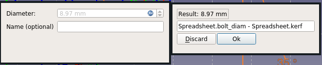
For the nut cutout, the kerf is subtracted from the diameter, since the laser kerf will enlarge this interior hole. On the other hand when constraining the motor bell, which is used as convex dimension of my part, the kerf has to be added to the diameter instead. I also added a slot for the clip to register in, which was also designed taking into account the kerf to subtract. Here is the full sketch (of the first prototype):
I then created a part from the sketch by padding it to the material thickness value from the spreadsheet, and finally mirrored it along the XZ plane in order to obtain a complete protector for one side of the quad.
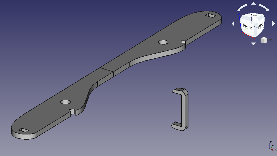
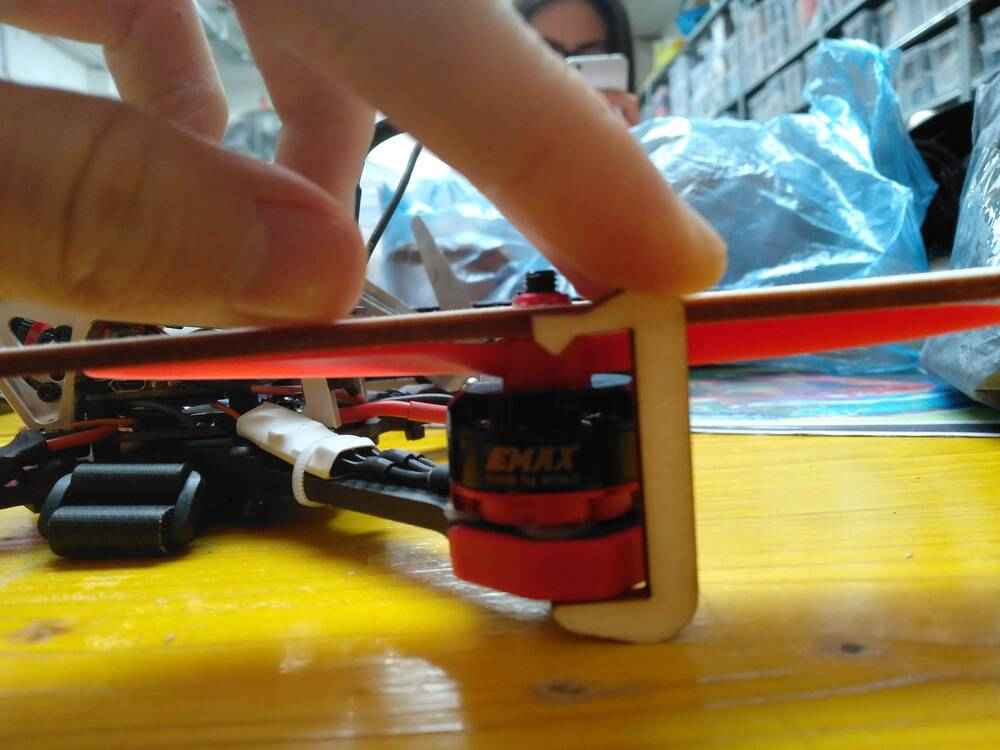
As I mentioned above, the guard is already arrested along two axes by the nut it registers with. Along the remaining axis, movement is also already prevented downwards, since the guard sits directly on top of the propellers, which are pressed onto the motor bell by the locknuts. This together with the geometry of the drone makes forces from below an unlikely problem, and so I decided to use a simple clip on each side that lightly clamps the cover to the carbon fiber frame underneath the motor.
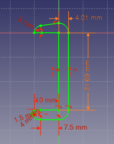
I sketched the first version on the XZ plane, so that it would be easier to assemble right away, but I later figured out that for purposes of exporting the drawing it is better to have all Sketches that will be exported as files for laser cutting to lie flat in the XY plane. Here is the initial sketch:
a2plus and TechDraw
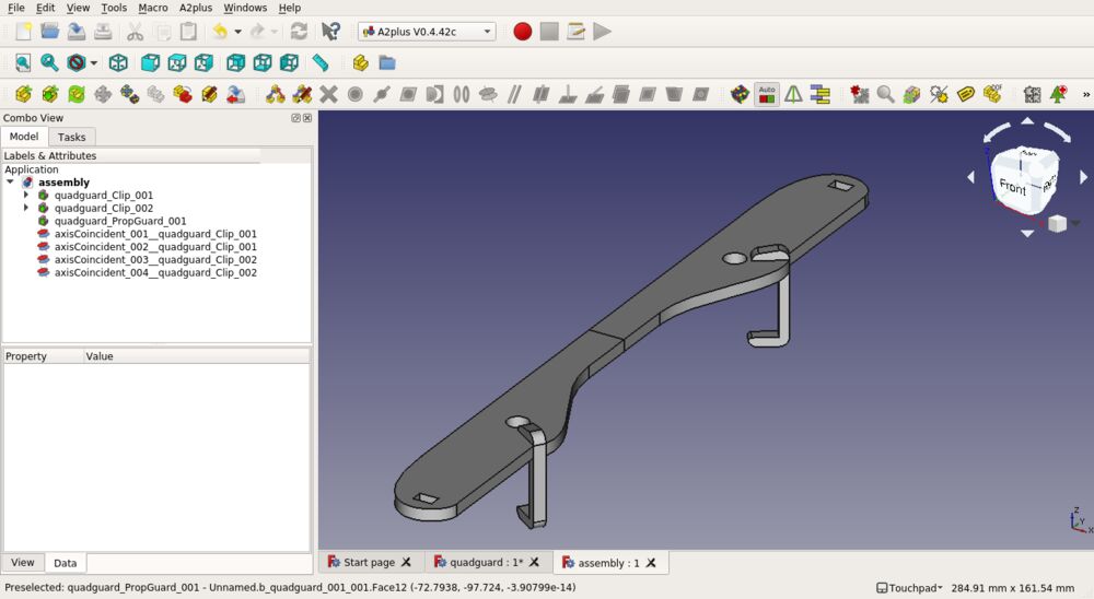
With the two parts done, I wanted to do an assembly using the a2plus
workbench. I couldn’t figure out how to do the assembly in the same file
without losing the ‘parametric-ness’ of the parts, so I ended up creating a
separate FreeCAD file for the assembly and importing the Parts using the “Add
single shape out of an external file” feature. Then I could constrain the clips
to the main piece using two orthogonal axis-coincident constraints each.
Then I switched to the TechDraw workbench and created a new Page with the
A2_Landscape_EN_m32 template. I added views of the Assembly, the two
Sketches, as well as a part of the Spreadsheet, which i think is a really nice
way to make sure that the parameters are known when the file is exported:

export and cutting
For exporting the design, it turned out to be easiest to use the drawing export
feature of TechDraw, which outputs an SVG or DXF file directly, and can export
drawings from any direction and with additional documentation overlaid. It is
also possible to directly export a single Sketch by selecting it in the Model
window and choosing Flattened SVG in File > Export, but this requires the
Sketch to be in the XY plane and doesn’t have any advanced options.
I really like the TechDraw workflow, so I ended up creating a second drawing
with a bank template, on which I added two views of the clip and arranged
everything ready to export for cutting straight away.
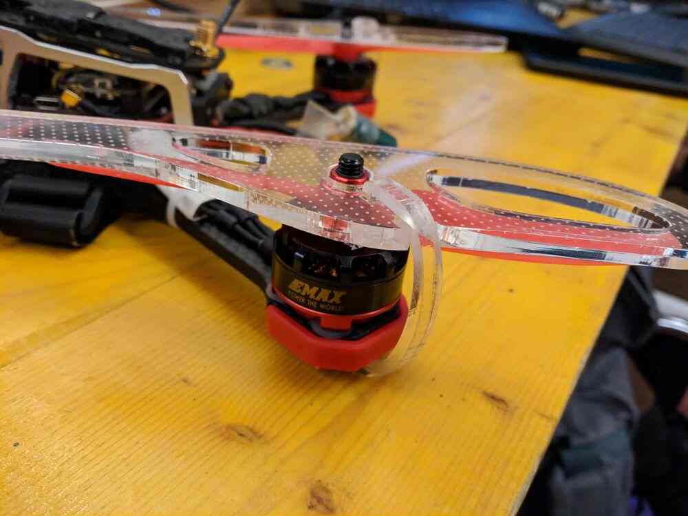
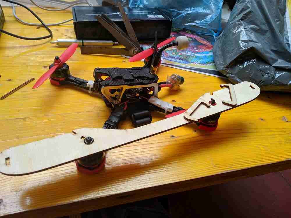
I cut the first test on 3mm plywood, and the main part of the design was an immediate success:
However I forgot to take the material thickness into account for the length of the clips, so they ended up 3mm short:
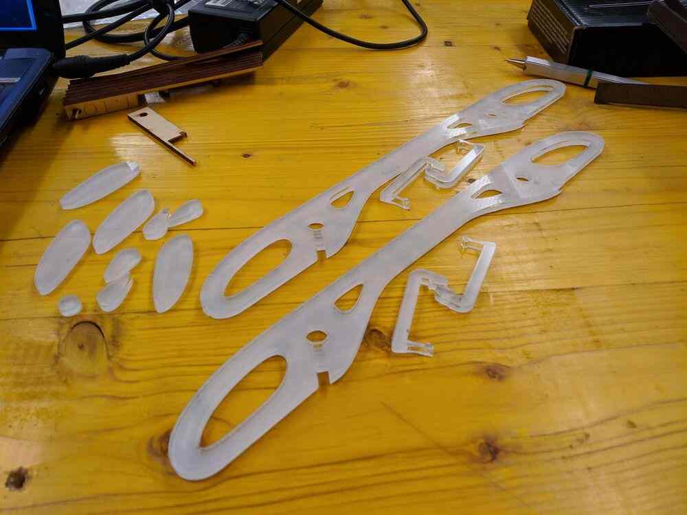
I made a second iteration of only the clips, and was rather satisfied with everything. It was getting close to the end of the day, but I wanted to do a ‘production’ run with a nicer (and thicker) material. My instructor gave me a sheet of 4mm transparent acrylic, which is also very nice to engrave. I went ahead and changed my file parameters for the new thickness - and this is where I got sloppy. I was rushing a bit, and didn’t pay enough attention when I measured the acrylic. Ideally I would have not only measured more accurately, but also done a test cut to measure the kerf with the new material. Instead I got clips that didn’t fit in the slot cut out for them.
I fixed the fit problem by sanding down the slots a bit, which was much faster and resource-effective than cutting a new pair of guards, but even then the clips didn’t end up working as expected. Since the clips of the last prototype were a bit too loose, I had added a small lip on the bottom of them, and thinned out the hook at the top to make it more flexible. It turned out that the new geometry was simply too tight and, as I found out trying to force them on, the thinner top and right angles really exacerbated the brittleness of the acrylic, making them snap in two very easily.
At this point I realized what should have been clear from the beginning: a clip
with right angle bends at the top and bottom was just not going to work neither
geometrically nor in being flexible enough to snap onto the slot as expected.
I redrew the clip from scratch, this time using half-ellipse arcs as the base
for a round ‘C’ shape. I made the thickness of the clip a design parameter and
cut three different versions to find a good compromise between rigidity and
flexibility of the clip. In the end the one with a width of 3mm worked best,
and I produced three more with the same dimensions. Due to my previous slip-up,
I still had to manually sand some spots on the three of them down, but this
only took a few minutes and then I finally had a set of clips that properly
clip on with an audible sound and stay in place.