Final Project - Aincrad
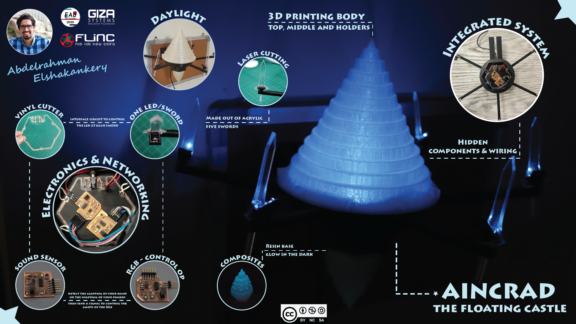
Aincrad is an interactive piece of furniture which is able to recognize the clapping sound to illuminate it's rgb-lighting system in the dark.
I have designed Aincrad body on Fusion 360, the top, middle and holders are 3D printing. the Base is
a
composites with the addition of phosphoric color to make it glow in the dark. the five swords are
made out
of
acrylic using the laser cutter.
For the electronics I use an ATtiny44 with MEMS Mic to detect the sound of
clapping hands or
snapping fingers then send a signal to the RGB-leds to control the lighting of
Aincrad top part.
each sword has a blue led and One of the main goals was to have a design as integrated as possible
so all of the electronics and wiring are hidden inside the middle
part of Aincrad.
This page is just the result of a lot of work done for several months. hope you enjoy it as I did!
What does it do?
Aincrad is an interactive piece of furniture which is able to recognize the clapping sound to illuminate it's rgb-lighting system in the dark.
Who's done what beforehand?
I couldn't find any one that built a real version of Aincrad, however I find a 3D design to
the
castle on Thingiverse
Also I found two youtube tutorial about how to make floating castle
What did you design?
I have designed from scratch all of Aincrad parts, from the body parts to the electronic boards.
What materials and components were used and where did they come from?
How much did they cost?
| # | Components | Amount | Unit price | Total cost | Where to buy? | Notes |
|---|---|---|---|---|---|---|
| 1 | Atmega328p-au | 1 | $2.87 | $2.87 | Digikey | Datasheet |
| 2 | 16MHz crystal | 1 | 5EGP | 5EGP | Alamir local store | |
| 3 | 22pf ceramic capacitor | 2 | 3EGP | 6EGP | Alamir local store | |
| 4 | 10uf ceramic capacitor | 2 | $0.1213 | $0.2426 | Digikey | |
| 5 | 10 kohm resistor | 1 | $0.01306 | $0.01306 | Digikey | |
| 6 | 499ohm resistor | 4 | $0.0291 | $0.1164 | Digikey | |
| 7 | green led | 1 | $0.15 | $0.15 | Digikey | |
| 8 | 2×2 pinheader | 1 | $0.71 | $0.71 | Digikey | |
| 9 | 1×3 pinheader | 1 | $0.23 | $0.23 | Digikey | |
| 10 | 2×3 pinheader for ISP | 1 | $0.65 | $0.65 | Digikey | |
| 11 | 1×6 pinheader for FTDI | 1 | $0.47 | $0.47 | Digikey | |
| 12 | Mic MEMS analog SPU0414HR5H-SB | 1 | $1.14 | $1.14 | Digikey | Datasheet |
| 13 | 0.1uf ceramic capacitor | 2 | $0.1662 | $0.3324 | Digikey | |
| 14 | LM3480- 3.3V | 1 | $0.6644 | $0.6644 | Digikey | Datasheet |
| 15 | 1kohm resistor | 10 | $0.0291 | $0.291 | Digikey | |
| 16 | RGB led | 3 | $0.53 | $1.59 | Digikey | Datasheet |
| 17 | N-Mosfet transistor | 3 | $0.2083 | $0.4166 | Digikey |
What parts and systems were made?
What processes were used?
For the design of Aincrad body I've used Fusion 360 ,3D printing and composite technique. For the
swords I've used illustrator and laser cutter.
for electronic boards I used kicad and the milling and soldering process using both machine CNC and
vinyl cutter. For the programming of the microcontrollers I used Arduino-IDE and Linux.
What questions were answered
how to fit all the castle structure together and all the elctronics components inside the structure in an integrated way as much as possible.
What worked? What didn't?
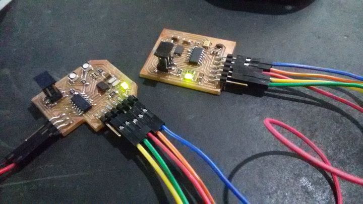
- At the beginning I've designed a one board using Atmega328 to be the single board (input-output) of Aincrad, however due to the time I end up use networking to communicate between the soundsensor board and the rgb-control board.
- The multi-color version of rgb-board didn't give the effect I was hopping for due to the two leds being really close to each others.
- At the beginning when I was creating the base I've used a 3D printing mold box instead of silicon and the result wasn't good at all.
Fabrication Process
Design
I've designed Aincrad body using Fusion 360.
The body is cosist of 5 Main components:
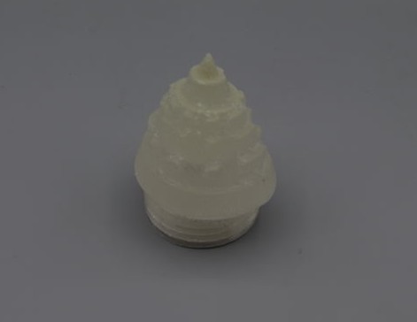
3D Printing
The top, middle,base thread and sword holders
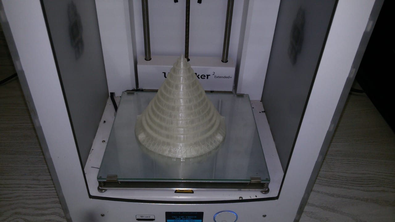 top part with transparent filmant.
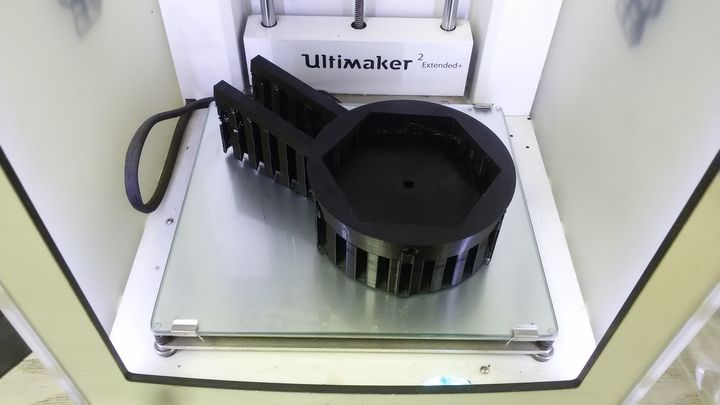 Middle part with black filament.
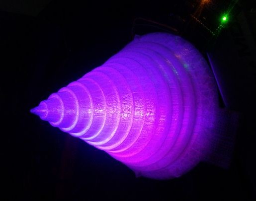
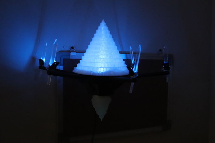
- A quick test to check the lights inside the castle.
 sword holder integrated with the middle part.
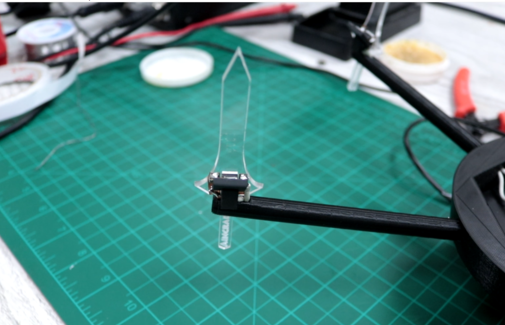
Laser cutting
I have made the swords out of acrylic using the laser cutter.
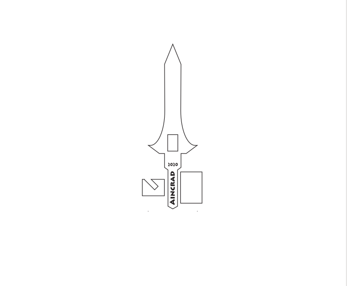 sword and led holder.
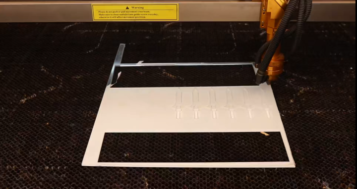 using the laser cutter
 power:50 , speed:25
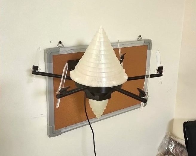
- A top view of the castle.
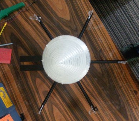
Molding and casting
At wildcard week I have created a composite of the base with the use of medical bandage and phosphoric colors.
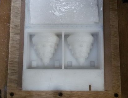 The molding box.
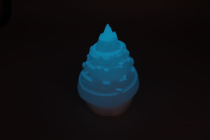
-
The glowing base.
Electronics design and production
The electronics part is consit of 4 main components:
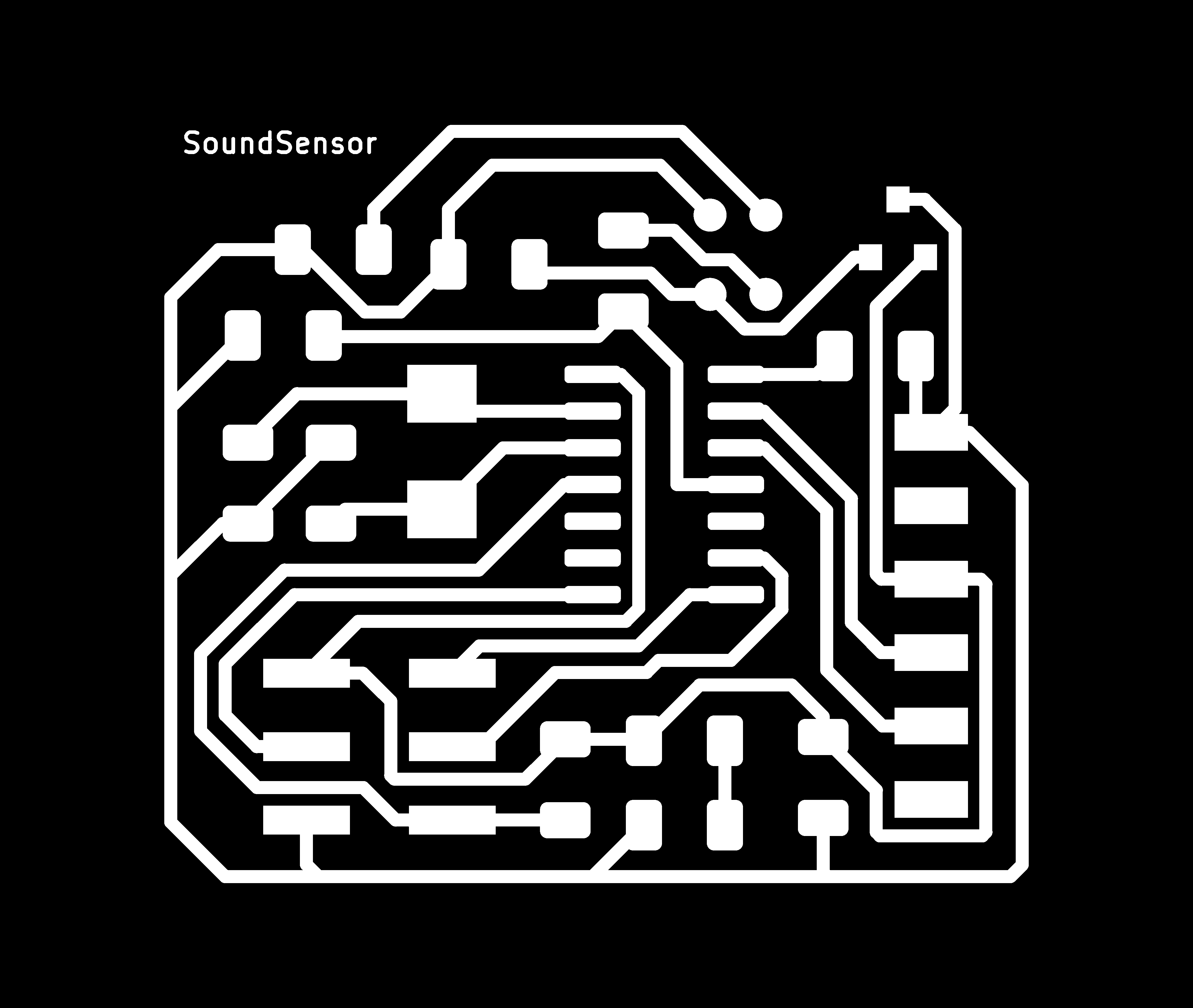
Input Circuit - Sound Sensor
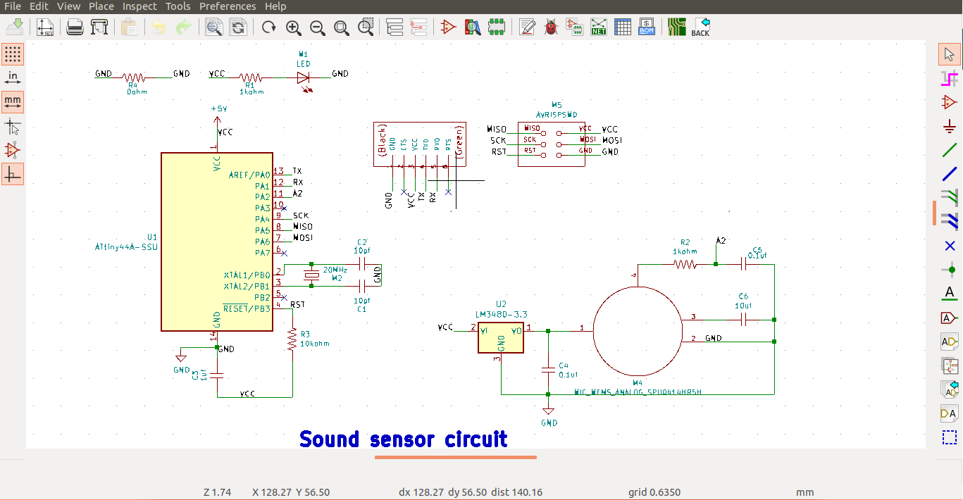 sound sensor schematic.
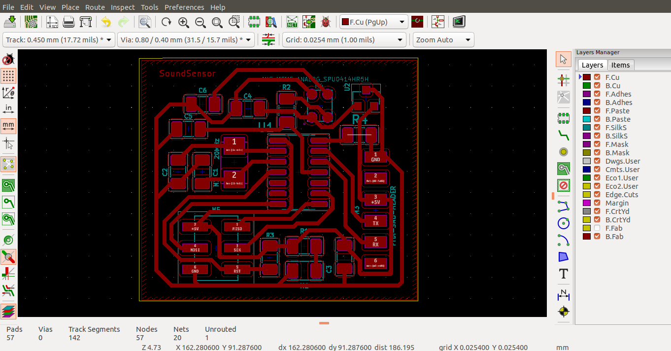 sound sensor layout.
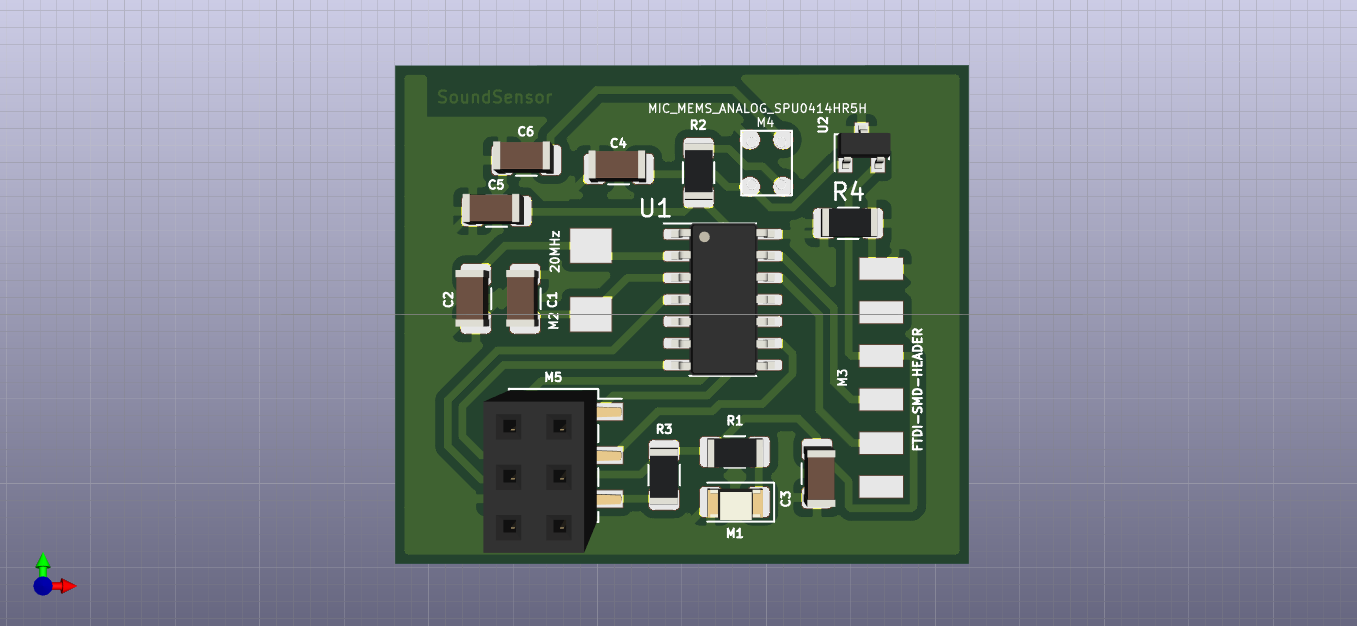 sound sensor 3D simulation.
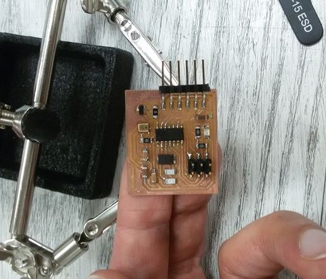
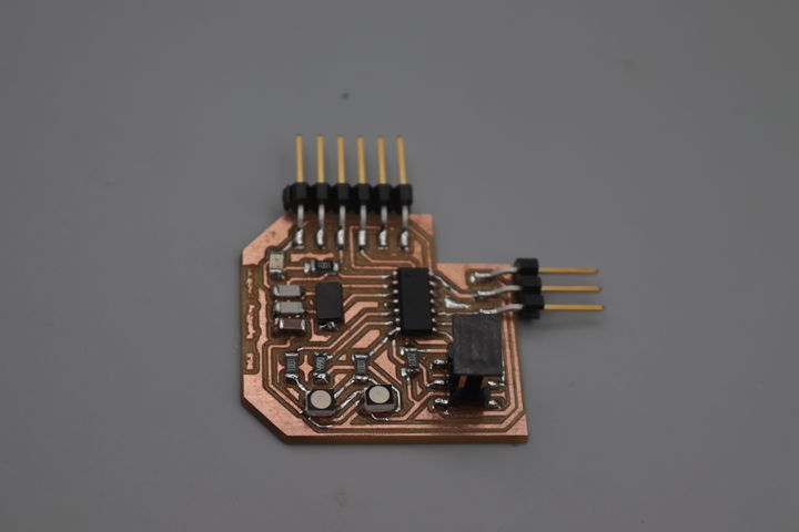
- sound sensor.
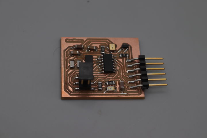 sound sensor.
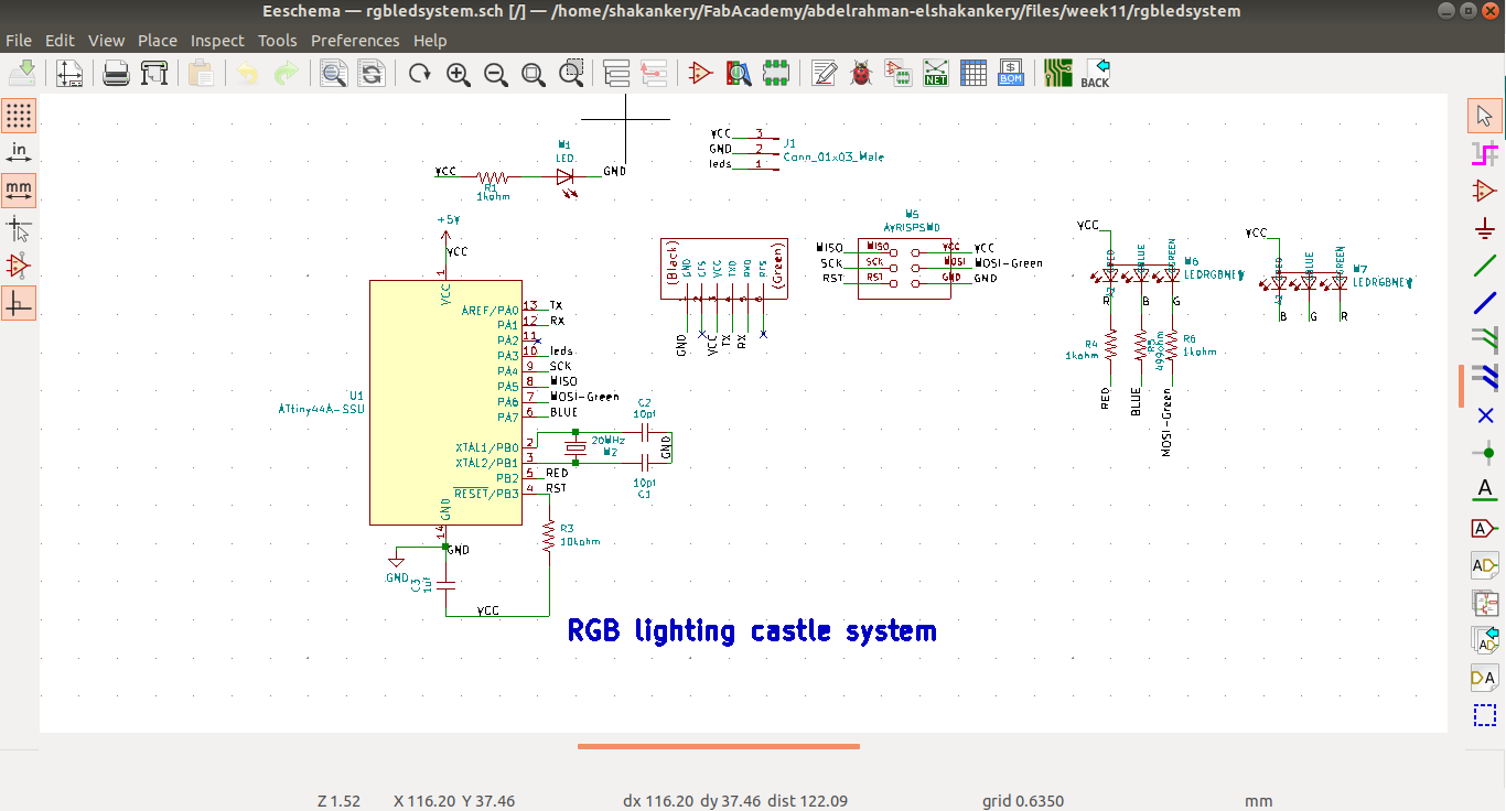 RGB-control schematic.
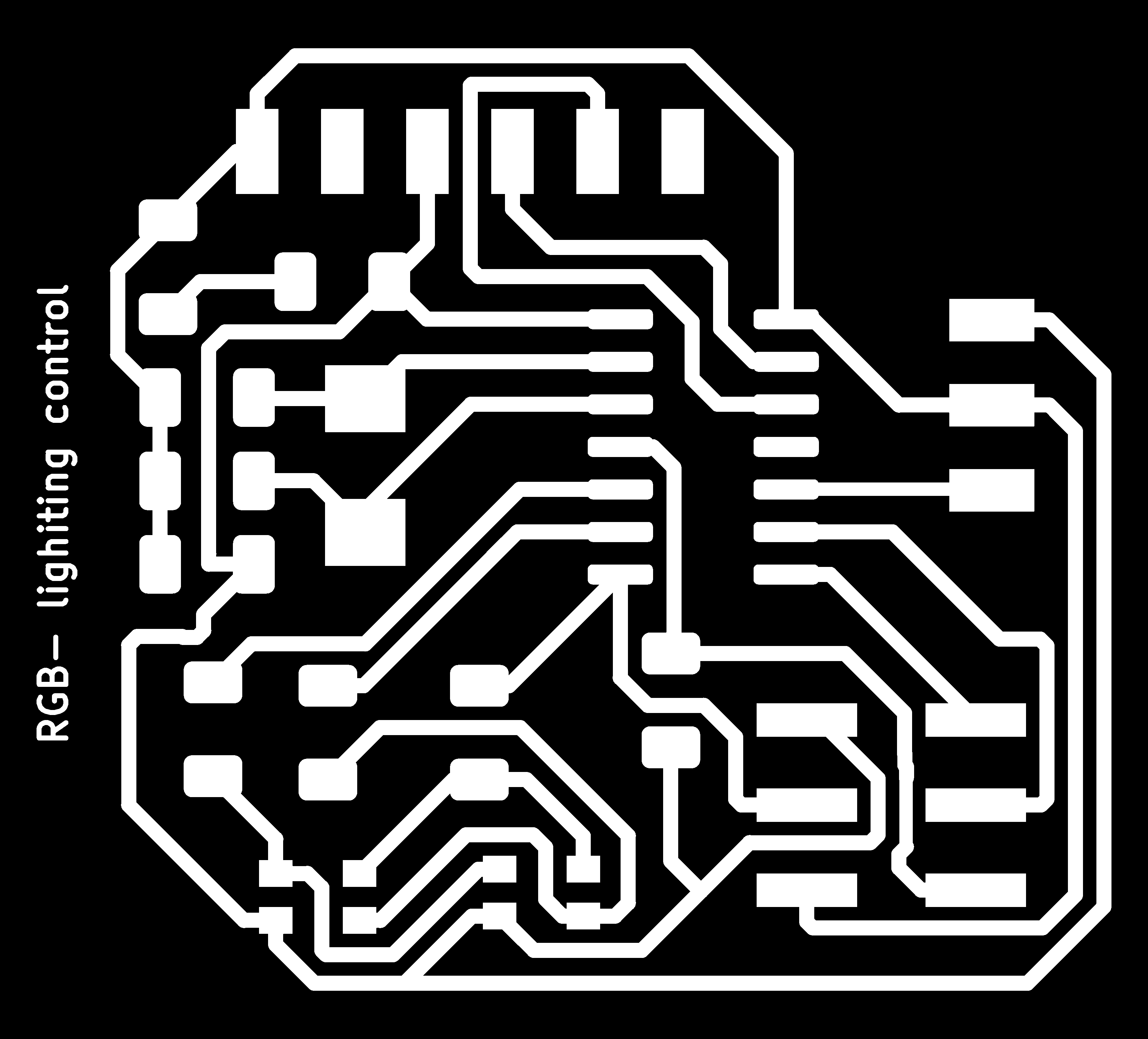
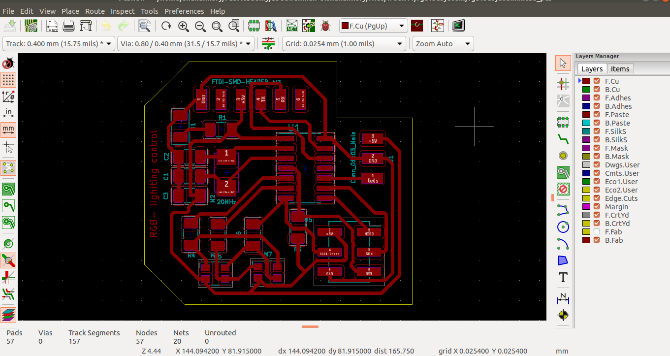 RGB-control layout.
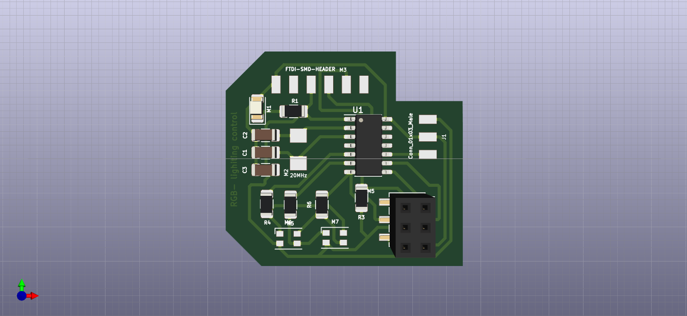 RGB-control 3D.
-
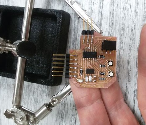
RGB-control.
 RGB-control.
-
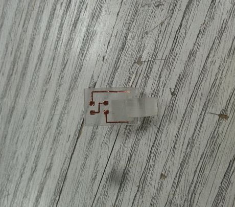
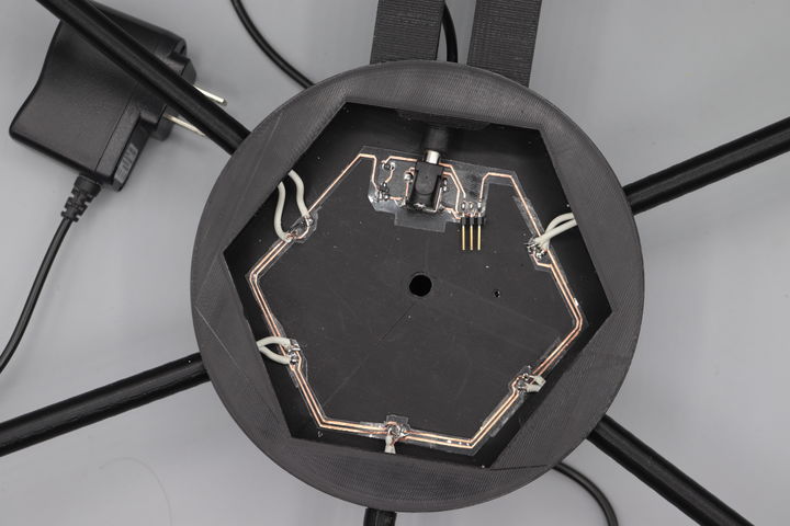
led sword interface circuit.
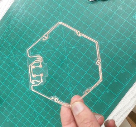
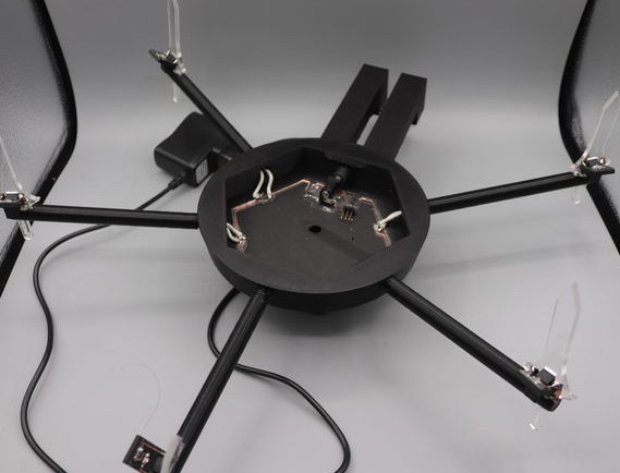
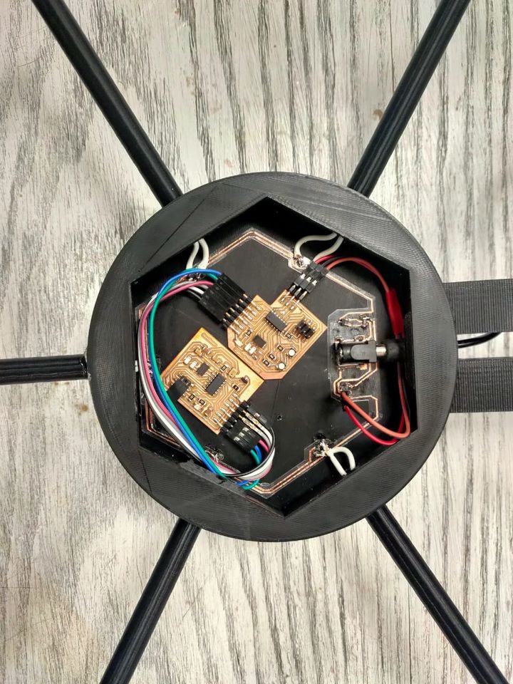
- integration hexagon circuit.
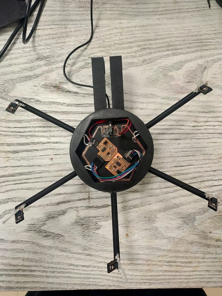
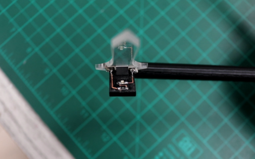 system assemply (1).
 system assemply (2).
 system assemply (3).
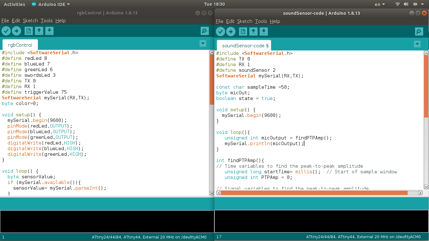
Embedded Microcontroller interfacing and programming
#include < SoftwareSerial.h >
#define redLed 8
#define blueLed 7
#define greenLed 6
#define swordsLed 3
#define TX 0
#define RX 1
#define triggerValue 75
SoftwareSerial mySerial(RX,TX);
byte color=0;

void setup() {
  mySerial.begin(9600);
  pinMode(redLed,OUTPUT);
  pinMode(blueLed,OUTPUT);
  pinMode(greenLed,OUTPUT);
  digitalWrite(redLed,HIGH);
  digitalWrite(blueLed,HIGH);
  digitalWrite(greenLed,HIGH);
}

void loop() {
  byte sensorValue;
  if (mySerial.available()){
    sensorValue= mySerial.parseInt();
  }
  else {
    sensorValue =0;
  }
  if (sensorValue >= triggerValue){
    rgbControl();
  }
}

void rgbControl (){
  digitalWrite (swordsLed,HIGH);
  switch (color){
    case 0:     //blue color
    analogWrite(redLed,220);
    analogWrite(blueLed,100);
    analogWrite(greenLed,255);
    color++;
    break;
    case 1:   //red color
    analogWrite(redLed,100);
    analogWrite(blueLed,255);
    analogWrite(greenLed,255);
    color++;
    break;
    case 2:   //green color
    analogWrite(redLed,255);
    analogWrite(blueLed,255);
    analogWrite(greenLed,100);
    color++;
    break;
    case 3:   //yellow color
    analogWrite(redLed,70);
    analogWrite(blueLed,250);
    analogWrite(greenLed,150);
    color++;
    break;
    case 4:   //Turn off
    digitalWrite(redLed,HIGH);
    digitalWrite(blueLed,HIGH);
    digitalWrite(greenLed,HIGH);
    color=0;
    digitalWrite (swordsLed,LOW);
    break;
  }
}
#include < SoftwareSerial.h >
#define TX 0
#define RX 1
#define soundSensor 2
SoftwareSerial mySerial(RX,TX);

const char sampleTime =50;
byte micOut;
boolean state = true;

void setup() {
  mySerial.begin(9600);
}

void loop(){
   unsigned int micOutput = findPTPAmp();
   mySerial.println(micOutput);
}

int findPTPAmp(){
// Time variables to find the peak-to-peak amplitude
   unsigned long startTime= millis();  // Start of sample window
   unsigned int PTPAmp = 0;

// Signal variables to find the peak-to-peak amplitude
   unsigned int maxAmp = 0;
   unsigned int minAmp = 1023;

// Find the max and min of the mic output within the 50 ms timeframe
   while(millis() - startTime < sampleTime)
   {
      micOut = analogRead(soundSensor);
        if( micOut < 1023) //prevent erroneous readings
        {
          if (micOut > maxAmp)
          {
            maxAmp = micOut; //save only the max reading
          }
          else if (micOut < minAmp)
          {
            minAmp = micOut; //save only the min reading
         }
       }
    }

PTPAmp = maxAmp - minAmp; // (max amp) - (min amp) = peak-to-peak amplitude
//double micOut_Volts = (PTPAmp * 3.3) / 1024; // Convert ADC into voltage
//Return the PTP amplitude.
return PTPAmp;
}
Networking
I have to connect the Tx of the soundsensor with the Rx of the RGB board to use the signal of the Sound sensor to control the RGB leds.
System integration
It was really important to me to make a clean integration that hide all of the components and wiring.
Files
Designs
3D printing
Electronics
Programming

This work is licensed under a Creative Commons Attribution-NonCommercial-ShareAlike 4.0 International License.