Week 11- Output Devices
Overview
For this week we have to Demonstrate workflows used in controlling an output device and MCU board:
- Group assignment
- Individual assignment
Measure the power consumption of an output device
Add an output device to a microcontroller board you've designed and program it to do something
Have you?
Documented what you learned from interfacing output device(s) to microcontroller and controlling the device(s).
Documented your design and fabrication process or linked to previous examples.
Explained the programming process/es you used.
Explained problems and how you fixed them.
Included original design files and source code.
Included a ‘hero shot/video’ of your board.
Linked to the group assignment page.
The Process
Pandemic version Individual Assignment
Rapid prototyping for Automated Ambu-bag
In able to prove the concept of the automated Ambu-bag we choose to make a quick prototype using arduino board.
in Stage One we have the following outputs to control
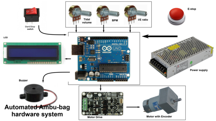
Automated ambu-bag hardware system for rapid prototyping
Wiring process for Outputs
for LCD:
- LCD K & Vss pin to GNd
- LCD A & VDD pin to 5 Volt
- LCD RS pin to digital pin 12
- LCD Enable pin to digital pin 11
- LCD D4 pin to digital pin 5
- LCD D5 pin to digital pin 4
- LCD D6 pin to digital pin 3
- LCD D7 pin to digital pin 2
- LCD Vo pin to the middle pin of 10K var.Resistor
for Motor Drive:
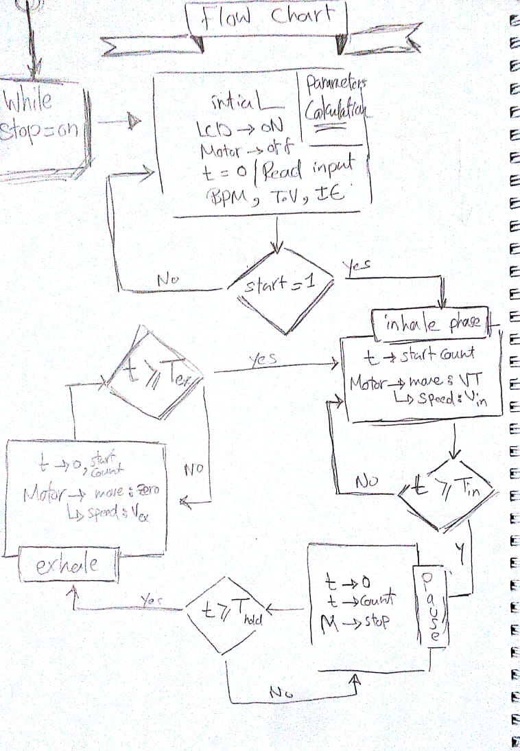
Control strategy and caculation
The goal is to provide a controlled volume of air to the patient in a set amount of time. There are three control phases: the inspiratory phase, the hold phase and the expiratory phase and for stage 1:
the motor will move distance= VT with speed = Q , when Q:is the flow rate
In stage two we will add the Motor encoder position.
In stage 3 we will add the system pressure and pulse oximeter.
we don't measure volume directly, So the tidal volume (VT) input of our controller is specified as a percent of a full compression.
The percent (%) of bag compression from 0 – 100% maps to the encoder pulses that correspond to how far the push arm move towards or away from the Ambu-bag and this determines the volume of air delivered.
Calculation
The Code
 #include < LiquidCrystal.h >
 #include "AmbuBag.h"
/*****
 Purpose: a constructor of the setInput class to read the controls and map the inputs
 Parameters:  void
 Return value: void
*****/
 setInputs::setInputs(void){
 tidalVolume=analogRead(TidalVolume);
 tidalVolume=map(tidalVolume,0,1023,0,100);
 breathPerMinute=map(breathPerMinute,0,1023,10,40);
 breathPerMinute=analogRead(RespiratoryRate);
 ieRatio=map(ieRatio,0,1023,1.0,11.0);
 ieRatio=analogRead(IEratio);
 lcd.setCursor(7,0);
 lcd.print("I/E=");
 lcd.print(ieRatio/10.0);
 lcd.print("TV=");
 lcd.setCursor(0,1);
 lcd.print(tidalVolume);
 lcd.print("% ");
 lcd.setCursor(9,1);
 lcd.print("RR=");
 lcd.print(breathPerMinute);
 lcd.print("/m");
}
/*****
 Purpose: calculate the inputs to get a valid data to control the inputs
 Parameters:  void
 Return value: void
*****/
 void setInputs::controlsCalculation(){
 totalTime= 60.0/breathPerMinute;
 inhaleTime= totalTime/(1+(ieRatio/10));
 exhaleTime= totalTime-inhaleTime;
 //converted to milisecond in order to use it in delay func.
 inhaleTime *=1000;
 exhaleTime *=1000;
 /*
 //will use it in stage 2 when mapping the tidalVolume to the motor encoder inputs
 inhaleFlowRate= tidalVolume/(inhaleTime);
 exhaleFlowRate= tidalVolume/(exhaleTime);
 */
 //for monitor the data and the operations
 Serial.println(totalTime);
 Serial.println(inhaleTime);
 Serial.println(exhaleTime);
 //Serial.println(inhaleFlowRate);
 //Serial.println(exhaleFlowRate);
}
/*****
 Purpose: squeeze the ambu bag by moving the motor with speed=70rpm, for time=inhaletime
 Parameters:  pointer to the setInputs class object in order to access the inhaleTime
 Return value: void
*****/
 void inhalePhase (setInputs *parameters)
 {
   Serial.println("InhalePhase");
   analogWrite(MotorDrivePwm,70);
   digitalWrite(MotorDriveDir,LOW);
   delay ((parameters->inhaleTime));
 }
/*****
 Purpose: Stop the motor for pause time in the end of the inhale and exhale phase
 Parameters:  void
 Return value: void
*****/
 void pausePhase (void)
{
  //for monitor the data and the operations
   Serial.println("PausePhase");
   //Motor control
   const float pauseTime=0.15;
   analogWrite(MotorDrivePwm,0);
   delay (pauseTime*1000);
}
/*****
 Purpose: release the ambu bag by moving the motor in the oposite direction with speed=70rpm, for time=exhaletime
 Parameters:  pointer to the setInputs class object in order to access the exhaleTime
 Return value: void
*****/
 void exhalePhase (setInputs *parameters)
{
   Serial.println("exhalePhase");
   analogWrite(MotorDrivePwm,70);
   digitalWrite(MotorDriveDir,HIGH);
   delay ((parameters->exhaleTime));
}

 void setup(){
   //set inputs pins for switch and motor drive
   pinMode(StartSwitch,INPUT);
   pinMode(LedPin,OUTPUT);
   pinMode(MotorDrivePwm,OUTPUT);
   pinMode(MotorDriveDir,OUTPUT);
   //LCD
   lcd.begin(16,2);
   lcd.setCursor(0,0);
   lcd.print("Inputs:");
   //for monitor the data and the operations
   Serial.begin(9600);
 }

 void loop(){
   while(digitalRead(StartSwitch)==LOW){
     digitalWrite(LedPin,LOW);
     setInputs parameters;
     pausePhase();
   }
   while(digitalRead(StartSwitch)==HIGH){
    digitalWrite(LedPin,HIGH);
    setInputs parameters;
    parameters.controlsCalculation();
    inhalePhase(¶meters);
    pausePhase();
    exhalePhase(¶meters);
    pausePhase();
 }
}
#include < LiquidCrystal.h >
#ifndef AmbuBag_h
#define AmbuBag_h

#define StartSwitch 6
#define LedPin 13
#define MotorDrivePwm 9
#define MotorDriveDir 8
#define TidalVolume A0
#define RespiratoryRate A1
#define IEratio A2

//intialize LCD library
const int rs = 12, en = 11, d4 = 5, d5 = 4, d6 = 3, d7 = 2;
LiquidCrystal lcd(rs, en, d4, d5, d6, d7);

class setInputs{
private:
int tidalVolume,breathPerMinute;
float ieRatio;
public:
float totalTime,inhaleTime,exhaleTime,inhaleFlowRate,exhaleFlowRate;
setInputs ();
void controlsCalculation(void);
};
#endif
This was our first test for the Nema17 which we choose without any power or torque calculations. so we only prove that the control system is working.
Motor Selection and power calculations
As I said for the first time we use the Nema17 without any calculations we did that actually for two reason
- we want to test to concept fast with what we have in the lab
- Nema17 was the motor that have the biggest torque in our lab ~=0.4N
So as much as we hoped it will work it didn't of course and Nema17 wasn't able to squeeze the Ambu-bag as you can see in the video ->
Group Assignment
Now it was to take step back and start to consider the power and torque calculations in order to choose the motor. which by the way wasn't that bad and I think if we could back in time we would do it from the beginning.
Motor Selection
In order to choose the right motor this time we need to run our calculations in the worst case in which the device will work
Worst case:
we assume the motor will squeeze the bag at maximumPressure= 40cmH2O,RespiratoryRate= 40bpm and inhaleTime=0.3sec.
when A:Ambu-Bag contact area & P=40cmH2O
when F:squeeze force & L:lenght of the squeeze arm
when RPM:angular velocity of squeeze arm= θ/inhaleTime
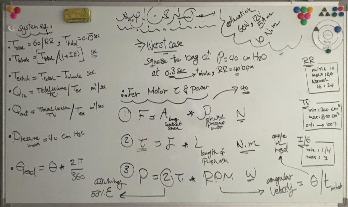 All of the equation for Stage1 in one picture.
From the calculation we need a motor with torque =0.7N ~= 1N
However here in egypt we can only find a Motor with much torque= 2.79N,20Watt so we adjust it and it work fine.
RGB Led control - Output devices
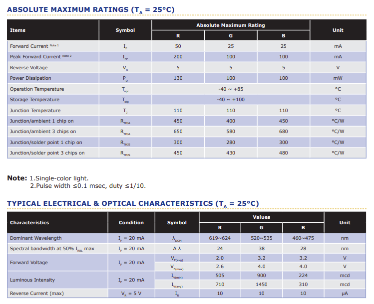
1) Cree PLCC4 3 in 1 SMD LED specifications and circuit design design
from RGB LED datasheet
- Size (mm):3.2 x 2.8
-
Dominant Wavelength:
- Red (619 - 624nm)
- Green (520 - 535nm)
- Blue (460 - 475nm)
-
Current= 20mA/Led when
- Red (2V)
- Green (3.2V)
- Blue (3.2V)
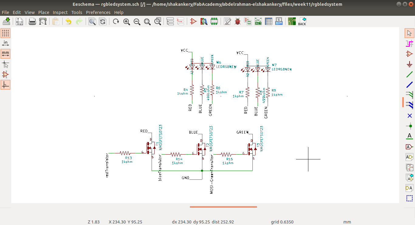
Circuit Components
However I would like to 2 LED's to the board, and I only have 4 PWM channels. So I'm going to
use n-channel transistors and duplicate per color channel pin
At 20mA per led, 3 per channel, that's only 60mA. so make sure the power supply can support
that.
60 * 2, that's 120mA on the leds alone, not including the rest of the board.
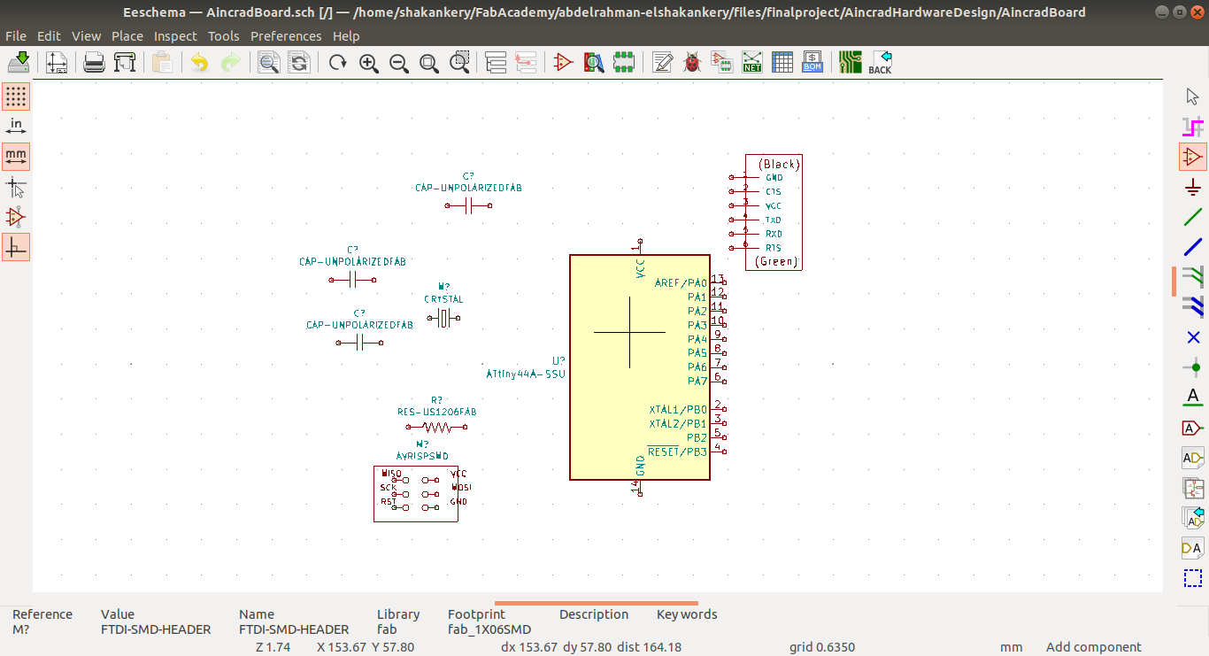
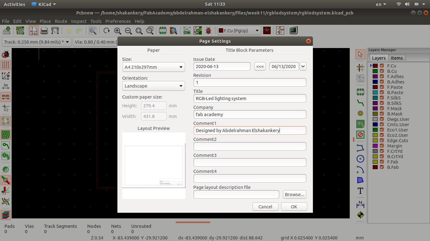
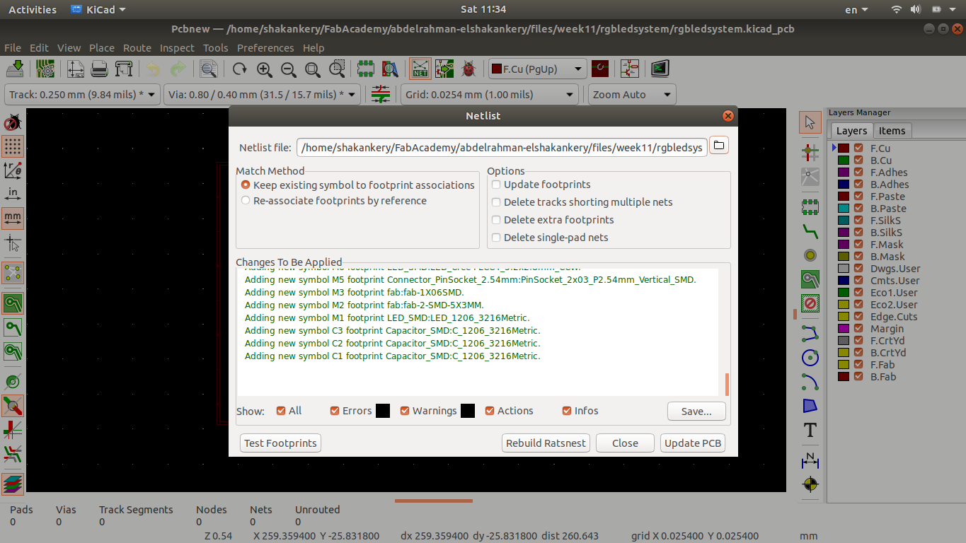
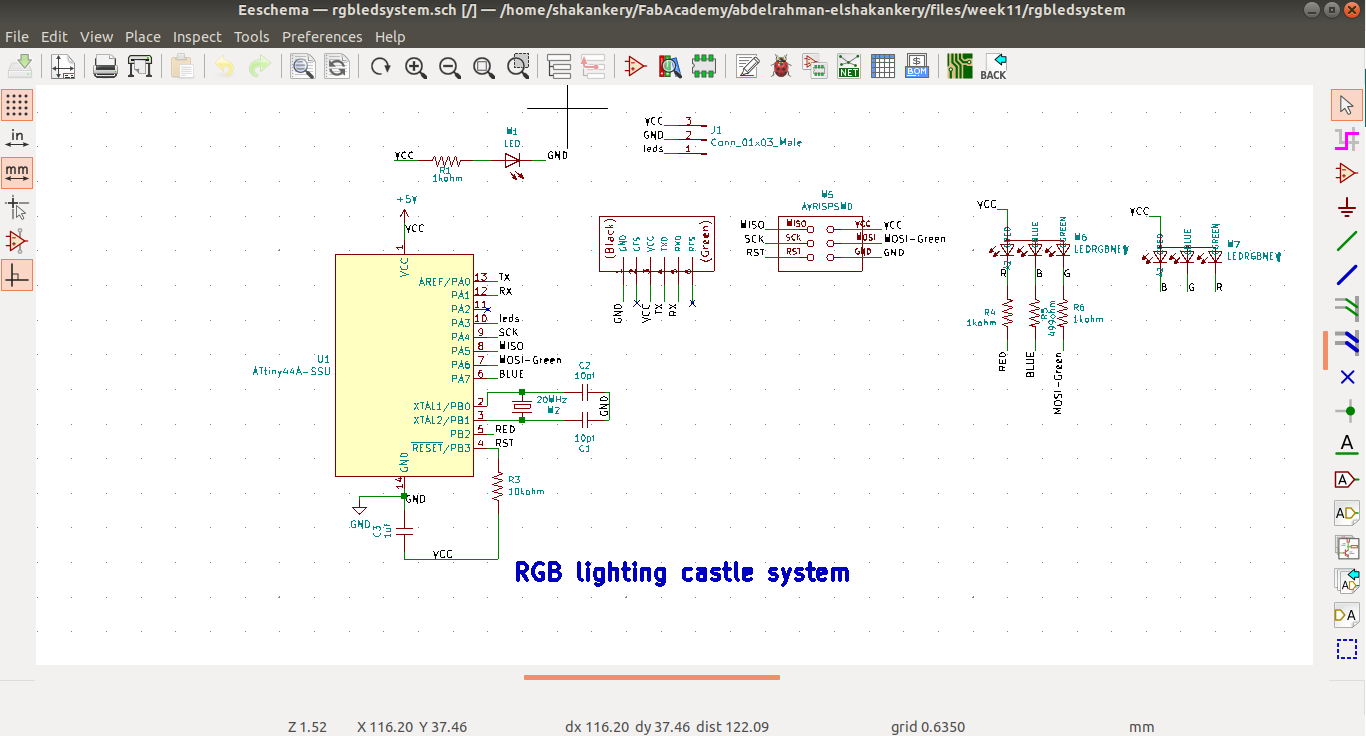
2) Schematic Design using Kicad
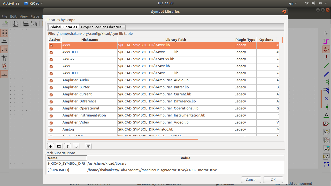
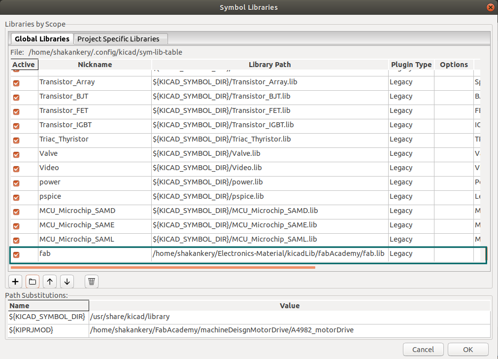
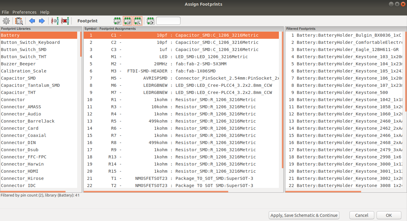
Download Fab-library:
you can find a fab-library with all the inventory component Here. download it then create a folder wherever you want for kicad folder to be kept.
along side that I open our flinc-inventory-sheet to make sure we have the same values of the components I need.
Circuit Components

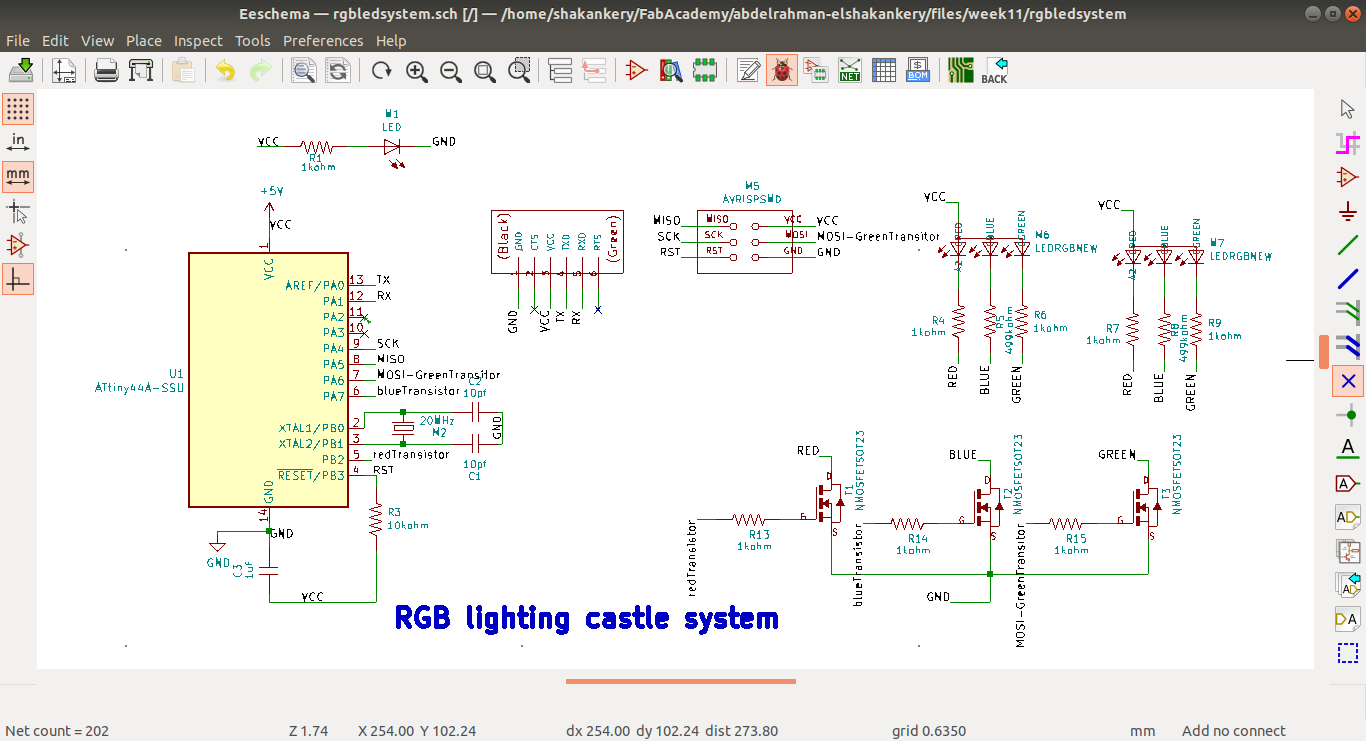
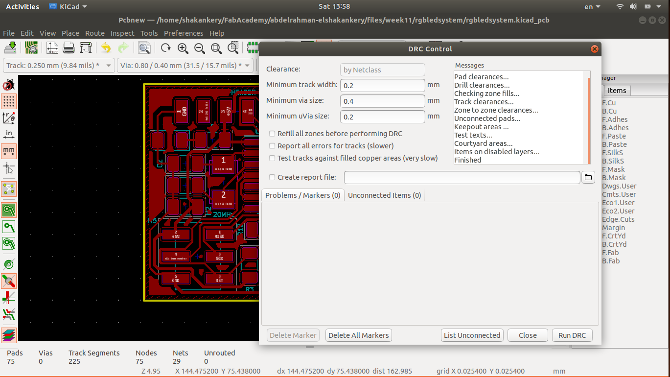
Generating the Netlsit is the final step after finishing all the design.
This step is really important in order to connect the schematic with PCBnew in which we will going
to create
the PCB layout.
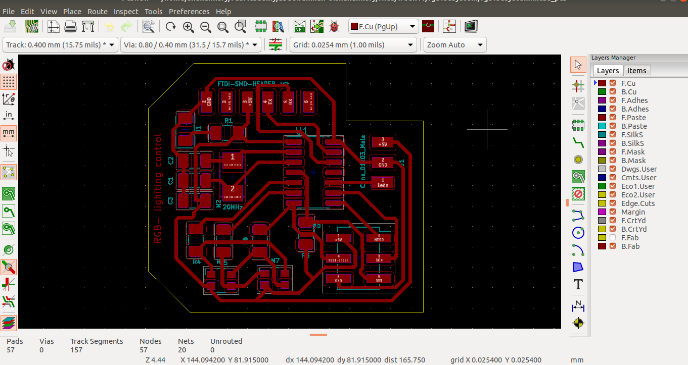
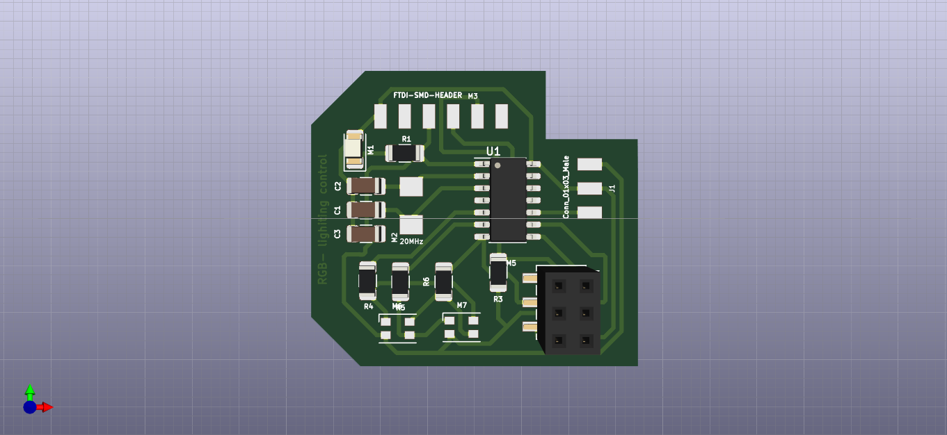
Now it's time for the layout design.
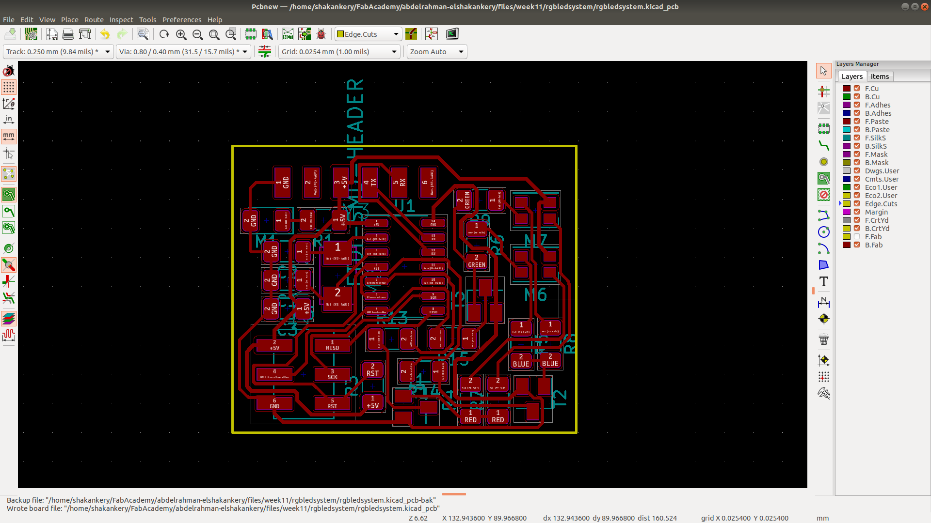
3)PCB layout
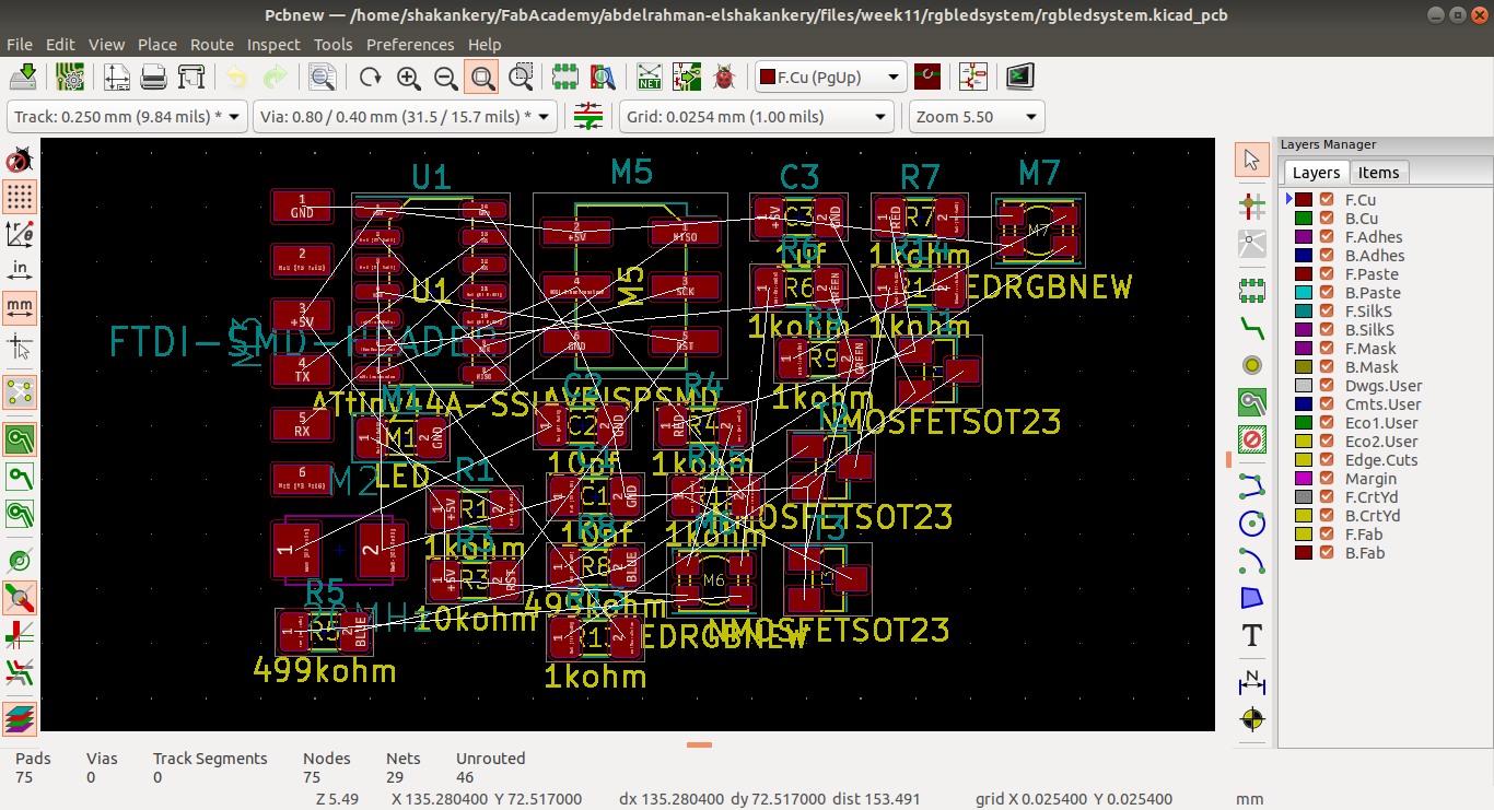
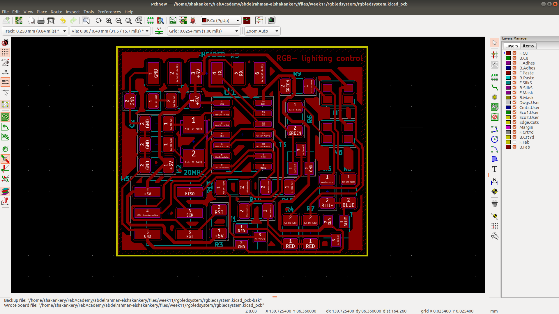
Modifications
When I acces the lab I found that we don't have an RGB-leds in our
inventory.
this was a
documentation error in our sheet so in order not to create a newer output circuit from scratch
my
instructor
Khaled order 10pcs from digikey at 3/7/2020 and we are hopping
to
get them within 10-14 day max.
While waiting the RGB to come and because of our limited time we have to access the lab I've
decided
to use my output and input board in my final project instead of creating a new master board
for
Aincrad
So I revist the RGB-control design. I know The circuit is to complex with a lot of
components in
a
small area in order to be able to control each led on it's own. Thus foer the sake of
simplicity
and
to make things more easier for me I decided to remove one of the RGB-led, all of the
transistor
and
conntect the remaining two
together in parallel.
this mean the two RGB-led will give us the same color and this fine by me :)
Yet I have an idea to creat a Multicolor version of the board by changing the connection between the leds for example connect a red led of one of the RGB to a blue led of the other RGB which mean the value I gonna send in my code will be different between the two leds giving us different colors.
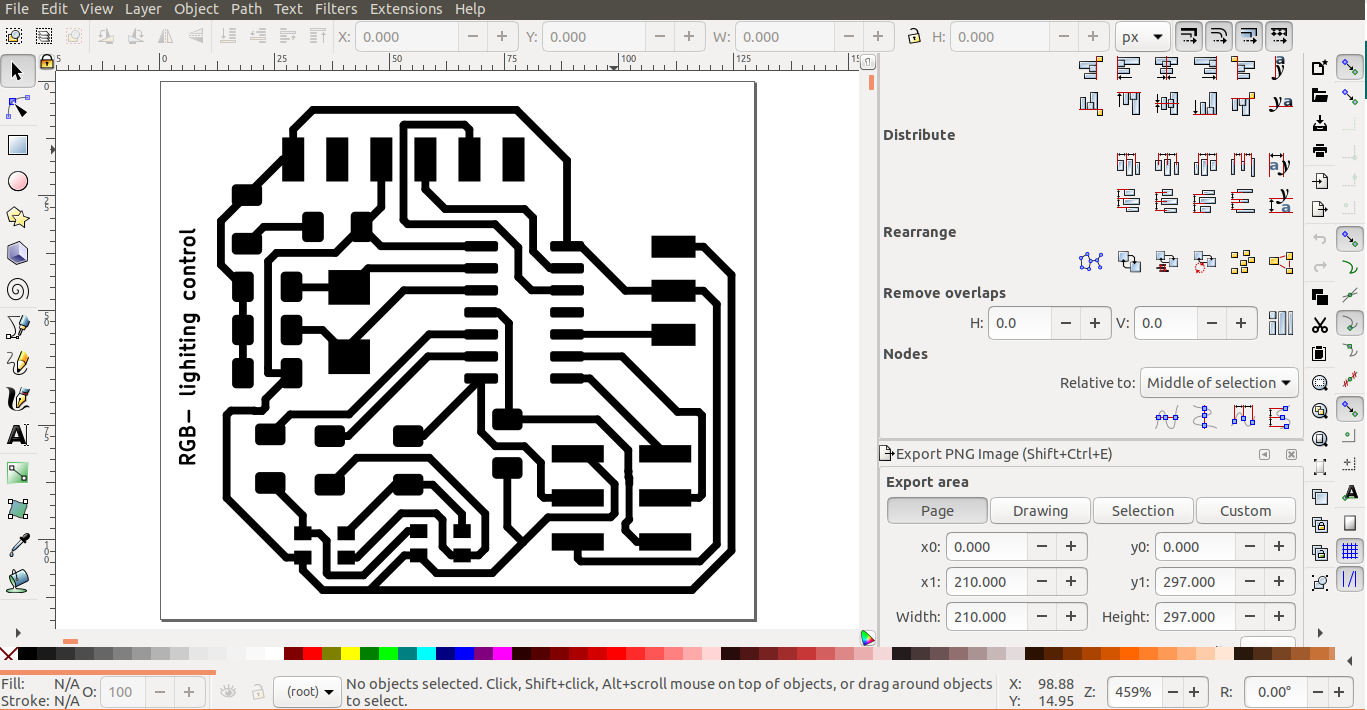
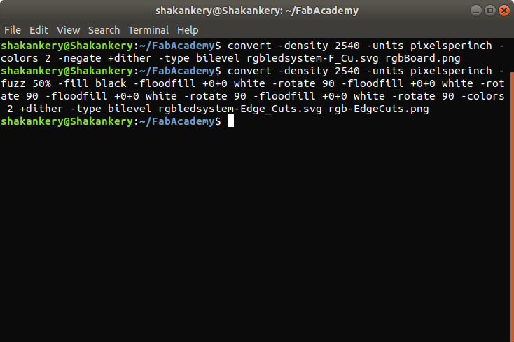
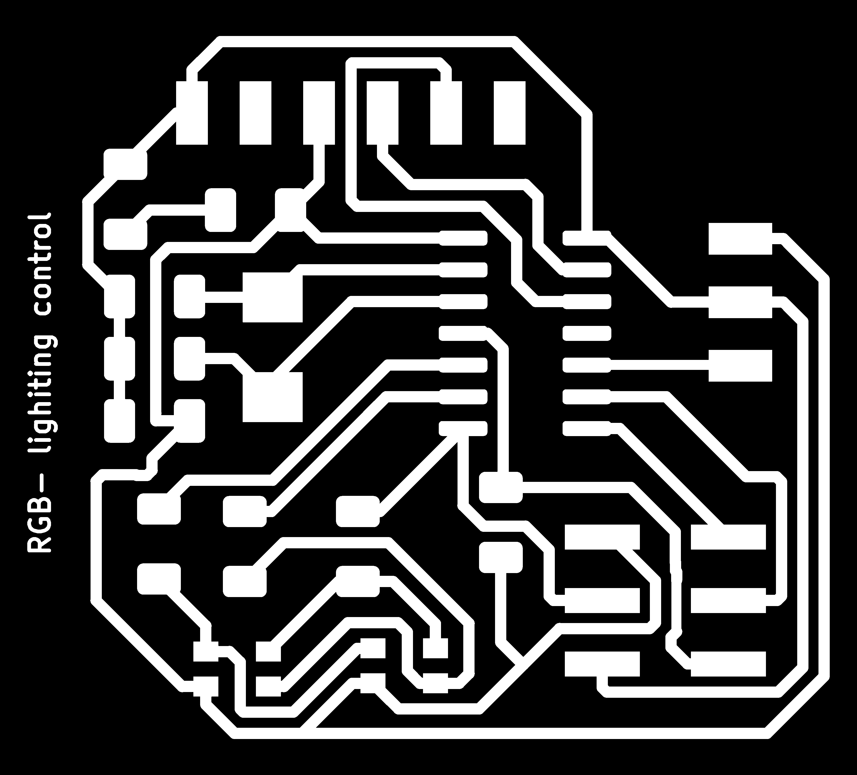
4) Create .png files for mods
Run our automatic conversion as we did in Input devices week
For the boardconvert -density 2540 -units pixelsperinch -colors 2 -negate +dither -type bilevel rgbledsystem-F_Cu.svg rgbBoard.pngFor the Edge-cut layer "Border"
convert -density 2540 -units pixelsperinch -fuzz 50% -fill black -floodfill +0+0 white -rotate 90 -floodfill +0+0 white -rotate 90 -floodfill +0+0 white -rotate 90 -floodfill +0+0 white -rotate 90 -colors 2 +dither -type bilevel rgbledsystem-Edge_Cuts.svg rgb-EdgeCuts.png

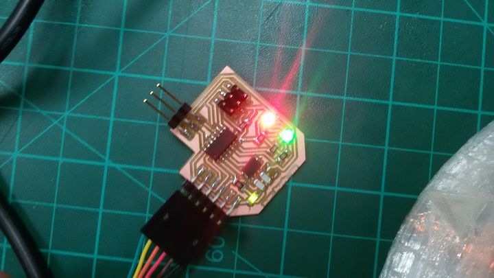
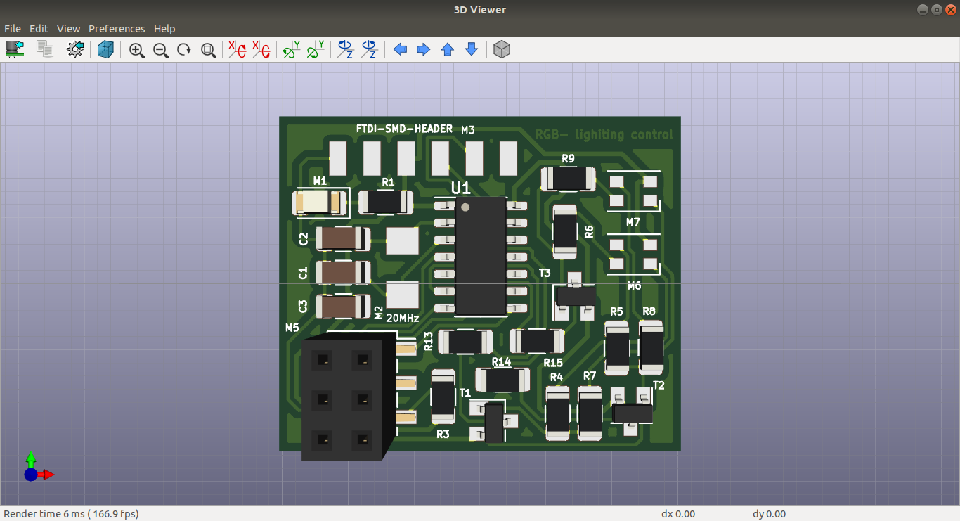
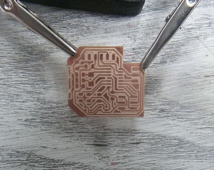
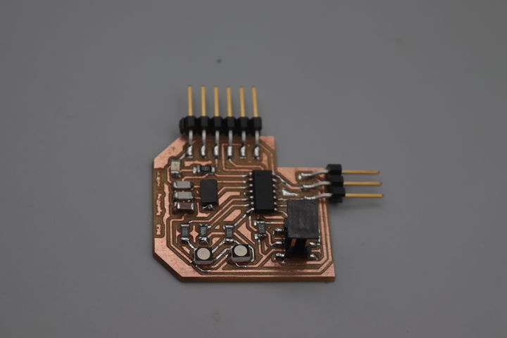
Milling and solder the circuit
following the same steps we did in Electronics production week I was able to solder and mill the circuit.
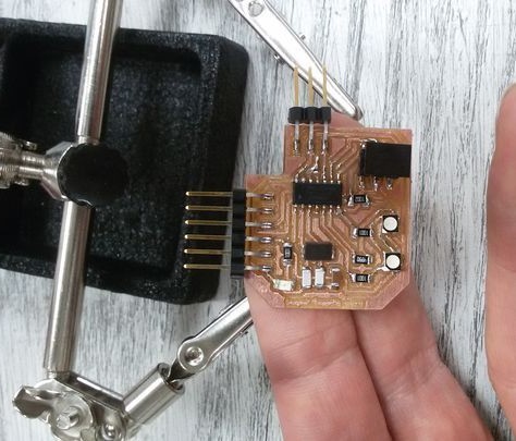
Programming and testing the circuit
#define redLed 8
#define blueLed 7
#define greenLed 6
void setup() {
  pinMode(redLed,OUTPUT);
  pinMode(blueLed,OUTPUT);
  pinMode(greenLed,OUTPUT);
}

void loop() {
    analogWrite(redLed,200);
    analogWrite(blueLed,20);
    analogWrite(greenLed,70);
   delay (1000);
   analogWrite(redLed,255);
    analogWrite(blueLed,10);
    analogWrite(greenLed,180);
   delay (1000);
}
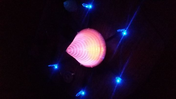
Teting RGB-board with Aincrad top part
Multicolor version.