Week 14- Networking and communication
Overview
For this week we have two assignments:
- Group assignment
- Individual assignment
Send a message between two projects
Design, build, and connect wired or wireless node(s) with network or bus addresses
Have you?
Documented your process.
Documented what you have learned from implementing networking and/or communication protocols.
Explained the programming process/es you used.
Outlined problems and how you fixed them.
Included design files (or linked to where they are located if you are using a board you have designed and fabricated earlier) and original code.
Linked to the group assignment page.
The Process
Pandemic version Individual Assignment
For this week I have an IR reciever in home so i decided to build a system to read one of my remote signals and use this signal to control a led.
Understand how IR remote controls work
IR remote controls, make use of pulses of infrared light to send signals to a receiving device such as a TV or Air conditioner. Each button on the remote control sends out a unique pattern of pulses which are decoded by the receiver so that the appropriate action (i.e. raise the volume, change temprature) can be taken.
Infrared light is perfectly safe to work with, actually The infrared part of the light spectrum is just below the visible spectrum, the name “infrared” means below red which is where they sit on a spectrum chart.
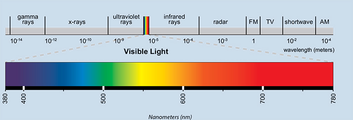 image from:eyelighting.com
Receiving IR codes requires a infrared sensor, my sensor have a three pins
GND, VCC, SignalOut
using an IR receiver with an Arduino is as simple as supplying 5 volts and Ground from the Arduino
and connecting the module or sensors output to one of the Arduino digital I/O pins.
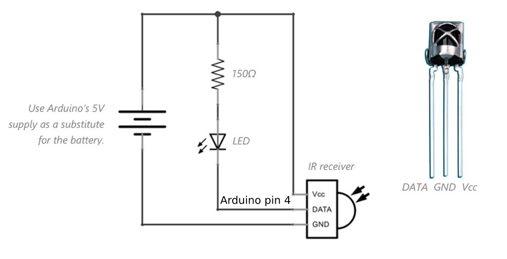 IR reciever circuit.
Interfacing Steps
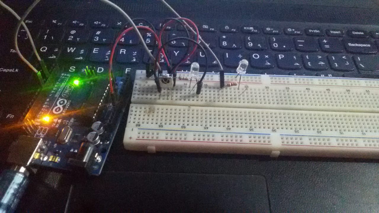 wiring the circuit.
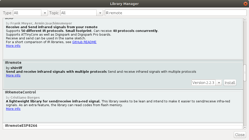 install IRRemote library
Writing the decoding and control code:
IR remote decode signals
#include < IRremote.h >

#define RECV_PIN 4    // Define sensor pin

// Define IR Receiver and Results Objects
IRrecv irrecv(RECV_PIN);
decode_results results;

void setup(){
  Serial.begin(9600);
  // Enable the IR Receiver
  irrecv.enableIRIn();
}

void loop(){
  if (irrecv.decode(&results)){
	// Print Code in HEX
		Serial.println(results.value, HEX);
		irrecv.resume();
  }
}
get the code of the remote control buttons.
IR control circuit
#include  < IRremote.h >

Define RecvPin 4      // Define sensor pin
Define LedPin 7       // Define Led pin
Define RecvRead 0x33B8A05F       // Define IR reading pin
bolean ToggleState=false;        //Define a state to switchled
// Define IR Receiver and Results Objects
IRrecv irrecv(RecvPin);
decode_results results;

void setup(){
  // Serial Monitor baud rate= 9600
  Serial.begin(9600);
  // Enable the IR Receiver
  irrecv.enableIRIn();
  pinMode(LedPin,OUTPUT);
}

void loop(){
  if (irrecv.decode(&results)){
	if (results.value==RecvRead){
		  switch (ToggleState){
			case false:
			digitalWrite(LedPin,HIGH);
			ToggleState=true;
			break;
			case true:
			digitalWrite(LedPin,LOW);
			ToggleState=false;
			break;
		  }
	}
	irrecv.resume();
  }
}
Serial Bus Communication
Since I had this assignment in mind when I designed my PCBs for input and output weeks, I only had to program the microcontrollers properly because I already had the communication connectors available on the PCBs
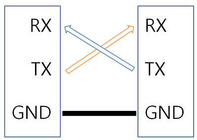
for this I am going to use the Serial Bus.the serial communication consists of two cables, TX (Transmitter) and RX (Receiver). Through these cables we can send and recieve the informations.
So I have to connect the Tx of the soundsensor with the Rx of the RGB board to use the signal of the Sound sensor to control the RGB leds.
Programming
I will use the Software Serial Library and define the TX and RX pins from the attiny 44 datasheet with transimition speed= 9600.
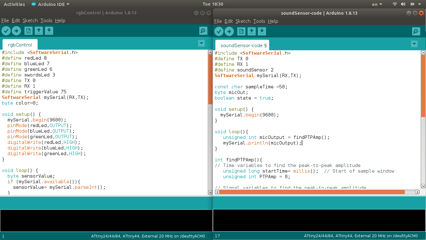
#include < SoftwareSerial.h >
#define TX 0
#define RX 1
#define soundSensor 2
SoftwareSerial mySerial(RX,TX);

const char sampleTime =50;
byte micOut;
boolean state = true;

void setup() {
  mySerial.begin(9600);
}

void loop(){
   unsigned int micOutput = findPTPAmp();
   mySerial.println(micOutput);
   //test a trigger value of clapping
   /* if (micOutput>=80){
	if(state){
	  mySerial.println("Led oN");
	  state= false;
	  }
	  else {
		mySerial.println("Led off");
		state=true;
	  }
	}*/
}

int findPTPAmp(){
// Time variables to find the peak-to-peak amplitude
   unsigned long startTime= millis();  // Start of sample window
   unsigned int PTPAmp = 0;

// Signal variables to find the peak-to-peak amplitude
   unsigned int maxAmp = 0;
   unsigned int minAmp = 1023;

// Find the max and min of the mic output within the 50 ms timeframe
   while(millis() - startTime < sampleTime)
   {
	  micOut = analogRead(soundSensor);
		if( micOut < 1023) //prevent erroneous readings
		{
		  if (micOut > maxAmp)
		  {
			maxAmp = micOut; //save only the max reading
		  }
		  else if (micOut < minAmp)
		  {
			minAmp = micOut; //save only the min reading
		 }
	   }
	}

PTPAmp = maxAmp - minAmp; // (max amp) - (min amp) = peak-to-peak amplitude
//double micOut_Volts = (PTPAmp * 3.3) / 1024; // Convert ADC into voltage
//Return the PTP amplitude.
return PTPAmp;
}
Sound sensor transimeter code
#include#define redLed 8 #define blueLed 7 #define greenLed 6 #define swordsLed 3 #define TX 0 #define RX 1 #define triggerValue 75 SoftwareSerial mySerial(RX,TX); byte color=0; void setup() { mySerial.begin(9600); pinMode(redLed,OUTPUT); pinMode(blueLed,OUTPUT); pinMode(greenLed,OUTPUT); digitalWrite(redLed,HIGH); digitalWrite(blueLed,HIGH); digitalWrite(greenLed,HIGH); } void loop() { byte sensorValue; if (mySerial.available()){ sensorValue= mySerial.parseInt(); } else { sensorValue =0; } if (sensorValue >= triggerValue){ rgbControl(); } } void rgbControl (){ digitalWrite (swordsLed,HIGH); switch (color){ case 0: //blue color analogWrite(redLed,220); analogWrite(blueLed,100); analogWrite(greenLed,255); color++; break; case 1: //red color analogWrite(redLed,100); analogWrite(blueLed,255); analogWrite(greenLed,255); color++; break; case 2: //green color analogWrite(redLed,255); analogWrite(blueLed,255); analogWrite(greenLed,100); color++; break; case 3: //yellow color analogWrite(redLed,70); analogWrite(blueLed,250); analogWrite(greenLed,150); color++; break; case 4: //Turn off digitalWrite(redLed,HIGH); digitalWrite(blueLed,HIGH); digitalWrite(greenLed,HIGH); color=0; digitalWrite (swordsLed,LOW); break; } }
RGB control reciever code
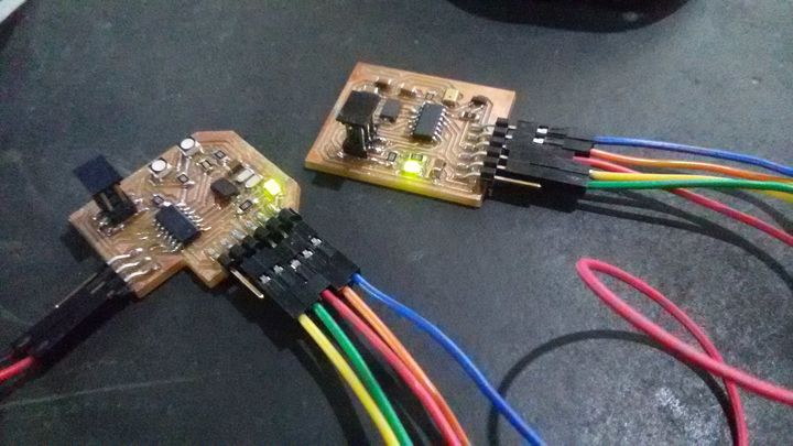
The connections between the 2 PCBs
-
- GND -> GND , Vcc -> Vcc
-
- Soundsensor Tx -> RGB Rx , Soundsensor Rx -> RGB Tx
Group Assignment
SEND A MESSAGE FROM MY BOARD TO THE COMPUTER
In Input device week I have send my soundsensor board reading to my computer throughout the serial monitor.
Files:
Find below the files that I made for this assignment. Please do not hesitate to download it!! I hope you enjoy