Week 15- Molding and Casting
Overview
For this week we have to design a 3D mould around the stock and tooling that you'll be using, mill it (rough cut + (at least) three-axis finish cut), and use it to cast parts.
Lets start by knowing the meanning of Molduing and casting
- Moulding: is the process of manufacturing by shaping liquid or pliable raw material using a rigid frame called a mold or matrix. This itself may have been made using a pattern or model of the final object. A mold or mould is a hollowed-out block that is filled with a liquid or pliable material such as plastic, glass, metal, or ceramic raw material. The liquid hardens or sets inside the mold, adopting its shape.
- Casting: is a manufacturing process in which a liquid material is usually poured into a mold, which contains a hollow cavity of the desired shape, and then allowed to solidify. The solidified part is also known as a casting, which is ejected or broken out of the mold to complete the process. Casting materials are usually metals or various cold setting materials that cure after mixing two or more components together; examples are epoxy and clay.
Have you?
Reviewed the safety data sheets for each of your molding and casting materials.
Documented how you designed your 3D mould and created your rough and finish toolpaths for machining, including machine settings.
Shown how you made your mould and cast the parts.
Explained problems and how you fixed them.
Included your design files and ‘hero shot’ of the mould and the final object.
The Process
Designing the Mold
From the begining I have decided to mold a small version of the top part of Aincrad
-my
final project-,
I have used Fusion 360 to make the design of the mold. I
create the
part by
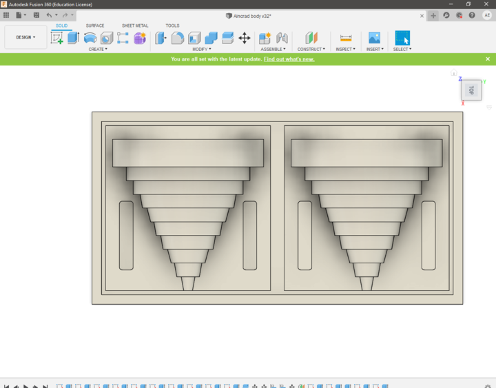
stacking and extruding 10 circles on top of each other. and because of it will be a mold of two
parts I
cut
the final shape in half then prepare the mold box with registration rectangles to join the two
parts.
-
design the top part of Aincrad using Fusion 360.
-
design the Mold box with registration rectangles
to join the two parts.
-
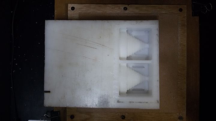
Top view for the Molding box that show the small step surrounding the entire box to improve the extraction of the silicon.
Milling the Mold
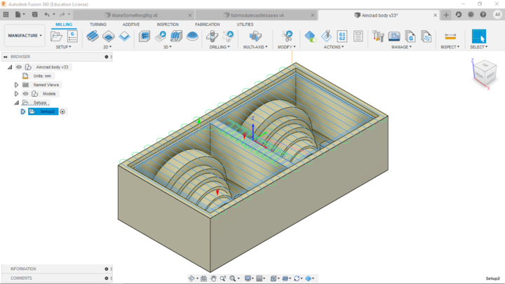
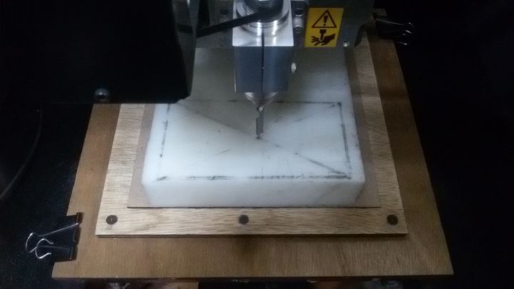
I'm going to use Fusion 360 Manufacturing workspace to create my CAM process as I did in week 7. then I will postprocess the G-code and use it with Roland Vpanel software to control our machine.
- MDX-40A
- 1 * 6mm flatend mill
- 1 * 4mm ballnose mill bit
- Artelon stock (millable material)
Tools
-
Facing the stock and 2D pocketing for the step that sround it.
-
Adaptive cleaning and pocketing for castle steps and registration rectangles.
-
Adaptive cleaning for cleaner finish.
-
drawing a box with the same dimensions of the model and created diagonals as shown in the photos where the point of intersection should be the origin point.
-
Facing the stock.
-
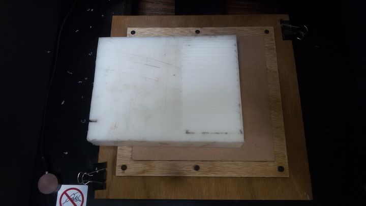
Pocketing the step around the mold.
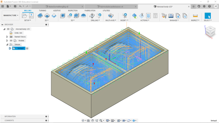
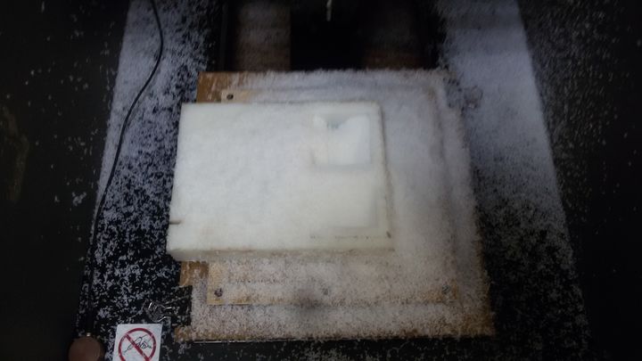
 Adaptive cleaning as a rough first milling, to remove more chips faster.
 Milling the registration rectangles.
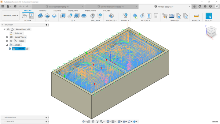
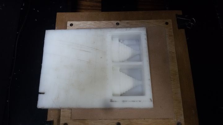
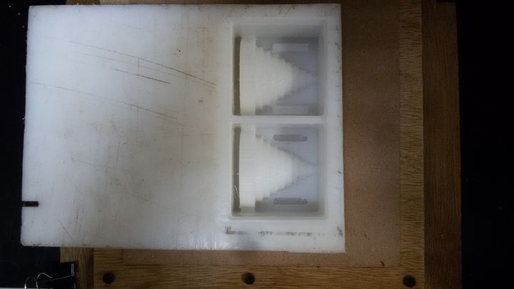 Finishing process.
 Final Molding box, however I realize that the 4mm bit didn't fit into one part of the design because narrow the distance between the part and the mold wall. This is my mistake as I forget I have to design for the tool I'm going to use.
 the solution I plan to use to correct it is to use the Dremel with the 2mm mill.
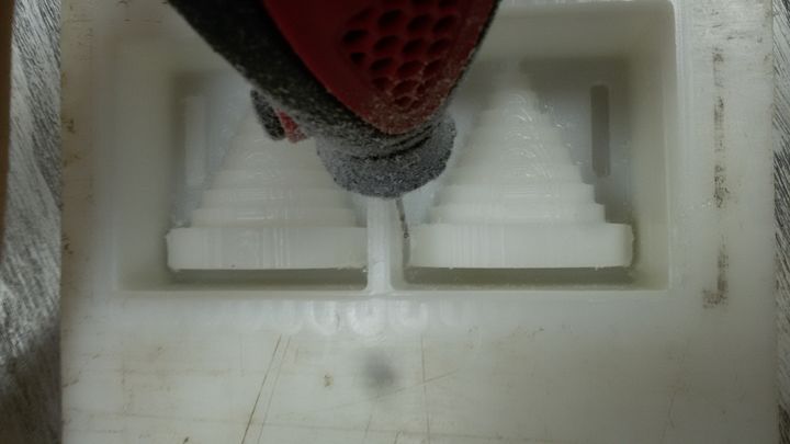 Manual milling.
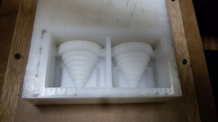
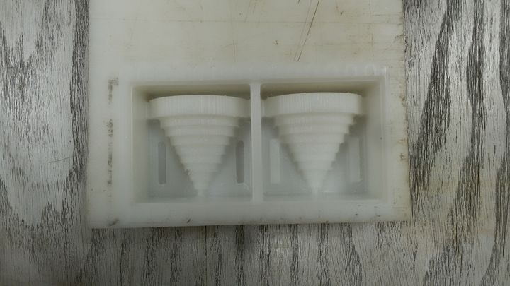
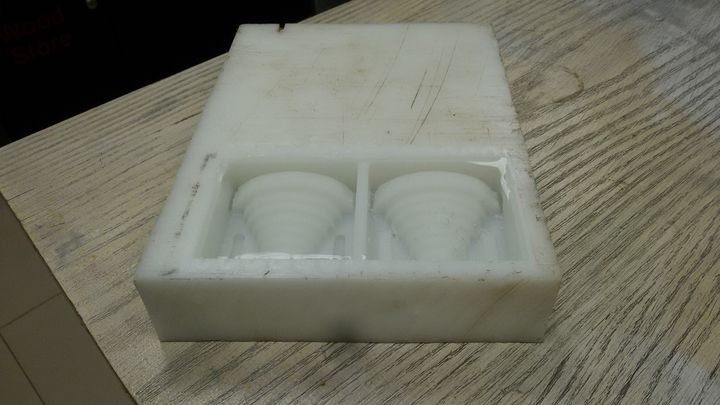
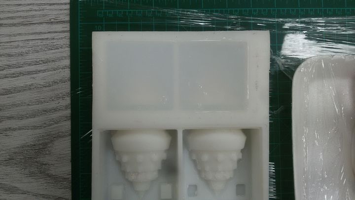
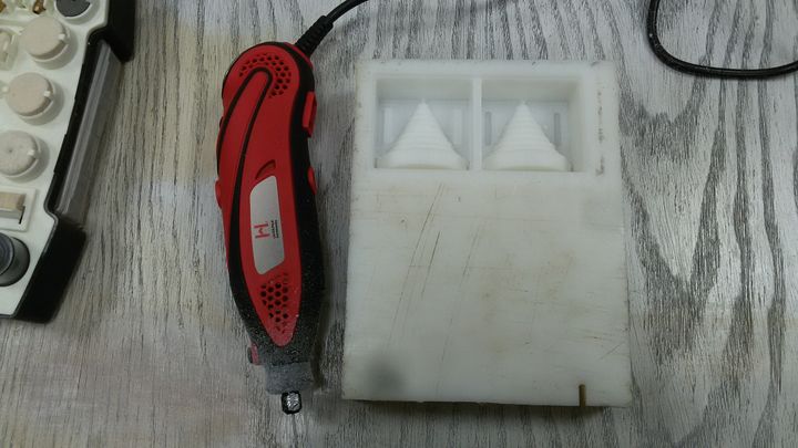 The real final molding box.
Calculate the volume of the mold
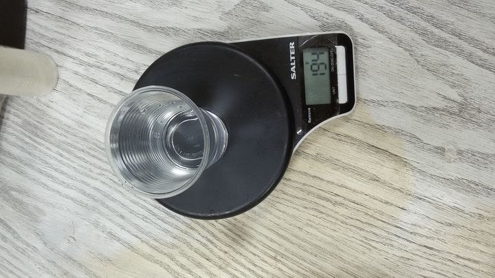
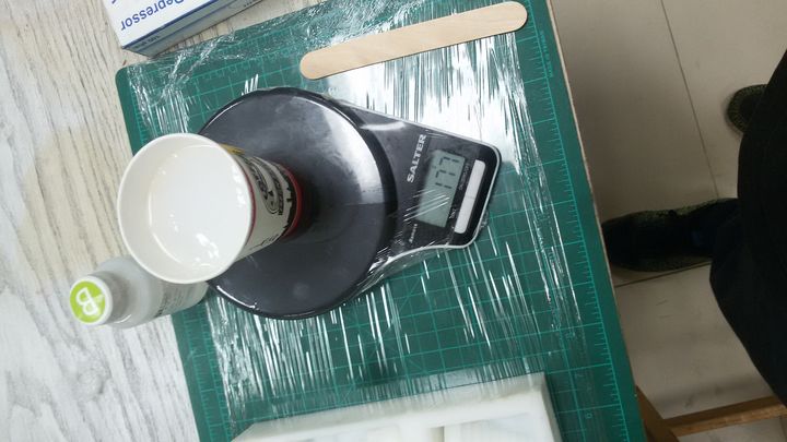
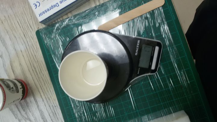
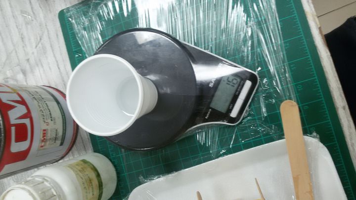
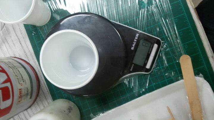
Once we have milled the wax mold, we have to calculate the volume of silicon that we are going to need. There are two options to do this either useing rice or useing water.
So I filled the mold with water and that amount of water is weighed. In theory, the density of water and weight are the same. In my case it is 194 grams with the plastic cup
Silicon Mold
safety data sheets for silicon rubber
- Use gloves during use and wash your hands after use.
- good ventilation is recommended.
- Allow rubber to cure a minimum of 16 – 24 hours.
- Avoid eating, drinking or smoking while use.
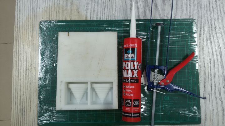
Silicone tube and gun
Because of the size of my molding box -194g- I want to try to make the negative silicone mold with the silicone tube insteade of the silicone rubber in order to save the material.
However because of the type of the material after 18hr I found that only the first layer of the silicone that has a direct contact with the air is turned to solid state and the rest remained in its fluid state
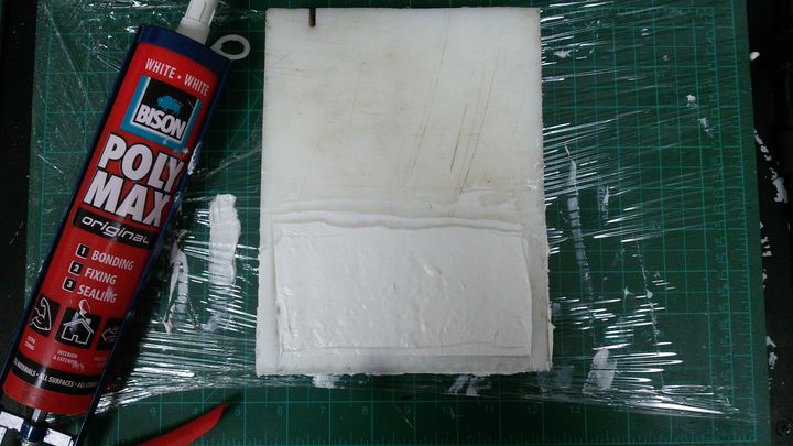
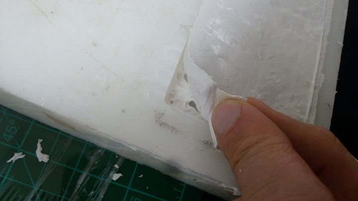
- First attemp failure.
Silicone rubber
this silicone should be mixed: 10 Part A: 1 Part B by weight or volume. So after measuring the volume of the mold and giving me 194g, I decided to round and put 170 grams of Part A and 17 grams of Part B.
I mix the two parts very carefully not to cause bubbles, for about 2 minutes. Then I pour it slowly with the help of the tounge depressure stick.
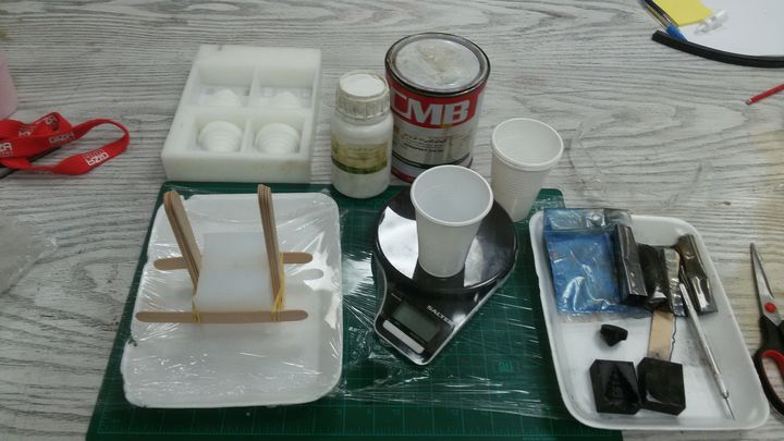
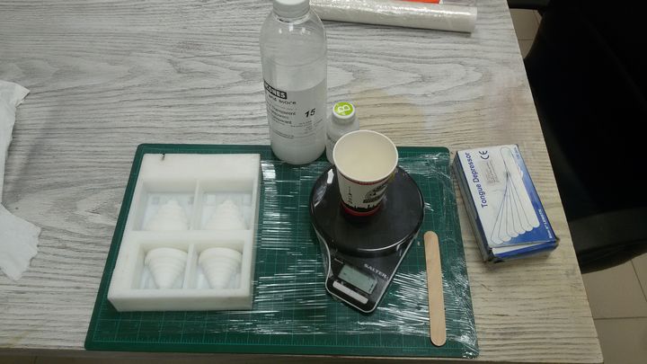 Silicon Rubber, hardner, pair of gloves, tounge depressure stick, a plastic cup and the Artelon milled mould.
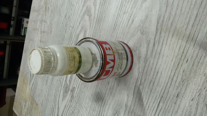
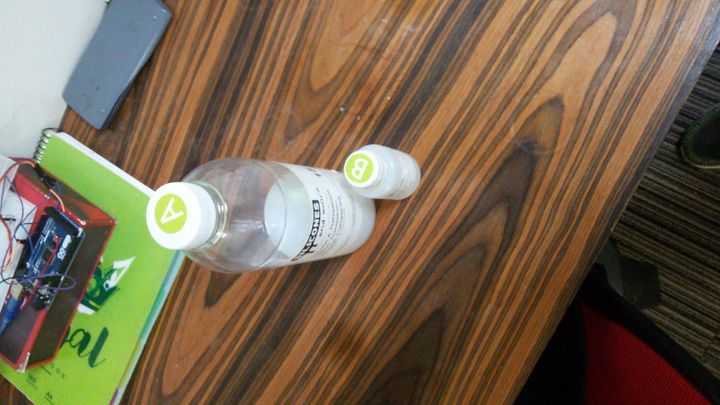 Silicone rubber and it's hardner
 Part A.
 Part B.
 tap around so that the bubbles are removed and rise upwards. I leave the mold like this for 24 hours.
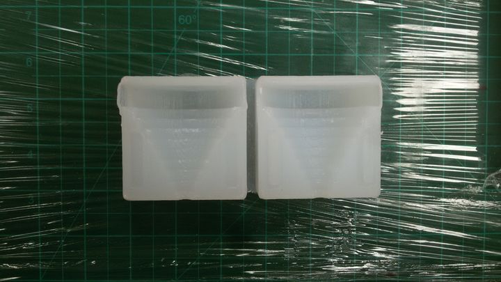 The final negative part of teh molding box.
Casting
safety data sheets for Kemapoxy 150 3D
For the Kemapoxy 150 3D I found a technical datasheet with safety instructions. The previous pre-cautions mentioned for silicon rubber applied as well for the EPOXY.
I removed the silicone from the artelon mold. Thanks to the edge, it is removed very well. There are no bubbles left, and the fit with the registrations is fine. I will need to use elastic bands to hold the two parts to pour the resin.
Similar to the previous process, I created a mixture with the ratio of 2 (EPOXY) : 1 (HARDNER).
I want to add 2 colors to my final mold so I pour first an approximate amount to fill the base and left it for 7hr then I create a new mixture with an approximate amount to the part steps with blue color and left it for 15hr.
 Epoxy, hardner, pair of gloves, tounge depressure stick, balck and blue mica color a plastic cup and the created silicon rubber mould
 Epoxy and it's hardner.
 Epoxy base amount.
 hardner base amount.
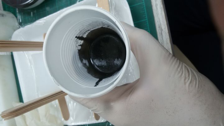 Add the mica color "black"
Conclusion
I learn so much from doing this assignment, yet I make 2 main mistake that I will make sure to avoid in my next assignment.
- make sure of my design part have an enough space from the mold box for the tool I'm going to use in my case it was 4mm and it wasn't enough that I had to make a manual milling.
-
The opening for pouring the epoxy was really small that it was hard to pour the mixture and it doesn't let the air out so the final part have a buuble on it outter surface.
I think this could be solved if I make the pouring opening from the base not the top.
Files
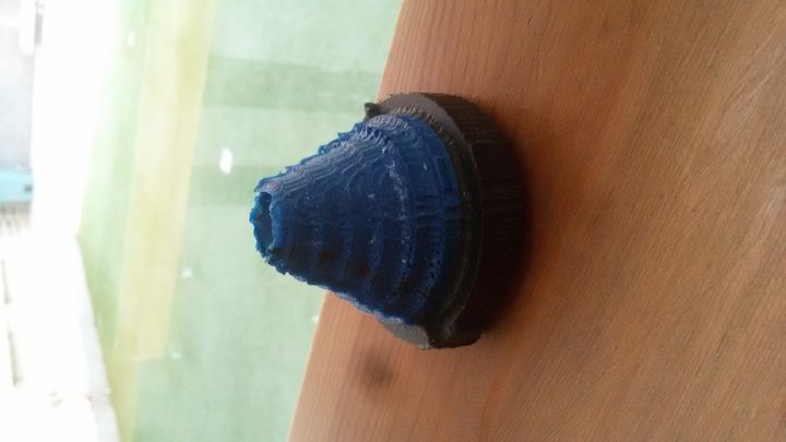 the final mold.