Week 9- Input Devices
Overview
For this week we have to Demonstrate workflows used in sensing something with input device and MCU board:
- Group assignment
- Individual assignment
Probe an input device(s)'s analog and digital signals
Measure something: add a sensor to a microcontroller board that I have designed and read it
Have you?
Documented what you learned from interfacing an input device(s) to microcontroller and how the physical property relates to the measured results.
Documented your design and fabrication process or linked to previous examples.
Explained the programming process/es you used.
Explained problems and how you fixed them.
Included original design files and source code.
Included a ‘hero shot/video’ of your board.
Linked to the group assignment page.
The Process
Pandemic version Individual Assignment
Rapid prototyping for Automated Ambu-bag
In able to prove the concept of the automated Ambu-bag we choose to make a quick prototype using arduino board.
in Stage One we have the following three parameters to control
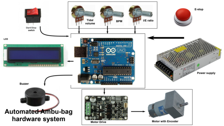
Automated ambu-bag hardware system for rapid prototyping
Input-controllers-stage 1:
Wiring process for inpusts
for 10k potiometer:
for Switch:
Control strategy and caculation
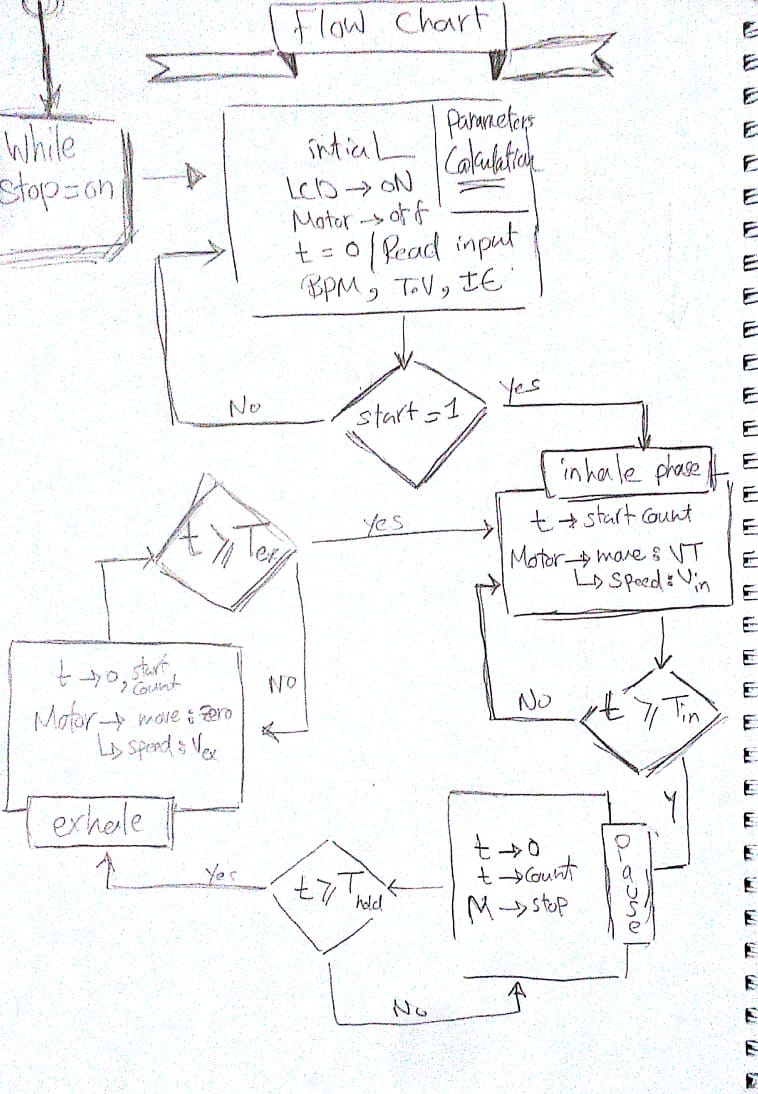
The goal is to provide a controlled volume of air to the patient in a set amount of time. There are three control phases: the inspiratory phase, the hold phase and the expiratory phase and for stage 1 we have three input parameters set by the clinician.
In stage two we will add the Motor encoder position.
In stage 3 we will add the system pressure and pulse oximeter.
we don't measure volume directly, So the tidal volume (VT) input of our controller is specified as a percent of a full compression.
The percent (%) of bag compression from 0 – 100% maps to the encoder pulses that correspond to how far the push arm move towards or away from the Ambu-bag and this determines the volume of air delivered.
Calculation
The Code
 #include < LiquidCrystal.h >
 #include "AmbuBag.h"
/*****
 Purpose: a constructor of the setInput class to read the controls and map the inputs
 Parameters:  void
 Return value: void
*****/
 setInputs::setInputs(void){
 tidalVolume=analogRead(TidalVolume);
 tidalVolume=map(tidalVolume,0,1023,0,100);
 breathPerMinute=map(breathPerMinute,0,1023,10,40);
 breathPerMinute=analogRead(RespiratoryRate);
 ieRatio=map(ieRatio,0,1023,1.0,11.0);
 ieRatio=analogRead(IEratio);
 lcd.setCursor(7,0);
 lcd.print("I/E=");
 lcd.print(ieRatio/10.0);
 lcd.print("TV=");
 lcd.setCursor(0,1);
 lcd.print(tidalVolume);
 lcd.print("% ");
 lcd.setCursor(9,1);
 lcd.print("RR=");
 lcd.print(breathPerMinute);
 lcd.print("/m");
}
/*****
 Purpose: calculate the inputs to get a valid data to control the inputs
 Parameters:  void
 Return value: void
*****/
 void setInputs::controlsCalculation(){
 totalTime= 60.0/breathPerMinute;
 inhaleTime= totalTime/(1+(ieRatio/10));
 exhaleTime= totalTime-inhaleTime;
 //converted to milisecond in order to use it in delay func.
 inhaleTime *=1000;
 exhaleTime *=1000;
 /*
 //will use it in stage 2 when mapping the tidalVolume to the motor encoder inputs
 inhaleFlowRate= tidalVolume/(inhaleTime);
 exhaleFlowRate= tidalVolume/(exhaleTime);
 */
 //for monitor the data and the operations
 Serial.println(totalTime);
 Serial.println(inhaleTime);
 Serial.println(exhaleTime);
 //Serial.println(inhaleFlowRate);
 //Serial.println(exhaleFlowRate);
}
/*****
 Purpose: squeeze the ambu bag by moving the motor with speed=70rpm, for time=inhaletime
 Parameters:  pointer to the setInputs class object in order to access the inhaleTime
 Return value: void
*****/
 void inhalePhase (setInputs *parameters)
 {
   Serial.println("InhalePhase");
   analogWrite(MotorDrivePwm,70);
   digitalWrite(MotorDriveDir,LOW);
   delay ((parameters->inhaleTime));
 }
/*****
 Purpose: Stop the motor for pause time in the end of the inhale and exhale phase
 Parameters:  void
 Return value: void
*****/
 void pausePhase (void)
{
  //for monitor the data and the operations
   Serial.println("PausePhase");
   //Motor control
   const float pauseTime=0.15;
   analogWrite(MotorDrivePwm,0);
   delay (pauseTime*1000);
}
/*****
 Purpose: release the ambu bag by moving the motor in the oposite direction with speed=70rpm, for time=exhaletime
 Parameters:  pointer to the setInputs class object in order to access the exhaleTime
 Return value: void
*****/
 void exhalePhase (setInputs *parameters)
{
   Serial.println("exhalePhase");
   analogWrite(MotorDrivePwm,70);
   digitalWrite(MotorDriveDir,HIGH);
   delay ((parameters->exhaleTime));
}

 void setup(){
   //set inputs pins for switch and motor drive
   pinMode(StartSwitch,INPUT);
   pinMode(LedPin,OUTPUT);
   pinMode(MotorDrivePwm,OUTPUT);
   pinMode(MotorDriveDir,OUTPUT);
   //LCD
   lcd.begin(16,2);
   lcd.setCursor(0,0);
   lcd.print("Inputs:");
   //for monitor the data and the operations
   Serial.begin(9600);
 }

 void loop(){
   while(digitalRead(StartSwitch)==LOW){
     digitalWrite(LedPin,LOW);
     setInputs parameters;
     pausePhase();
   }
   while(digitalRead(StartSwitch)==HIGH){
    digitalWrite(LedPin,HIGH);
    setInputs parameters;
    parameters.controlsCalculation();
    inhalePhase(¶meters);
    pausePhase();
    exhalePhase(¶meters);
    pausePhase();
 }
}
#include < LiquidCrystal.h >
#ifndef AmbuBag_h
#define AmbuBag_h

#define StartSwitch 6
#define LedPin 13
#define MotorDrivePwm 9
#define MotorDriveDir 8
#define TidalVolume A0
#define RespiratoryRate A1
#define IEratio A2

//intialize LCD library
const int rs = 12, en = 11, d4 = 5, d5 = 4, d6 = 3, d7 = 2;
LiquidCrystal lcd(rs, en, d4, d5, d6, d7);

class setInputs{
private:
int tidalVolume,breathPerMinute;
float ieRatio;
public:
float totalTime,inhaleTime,exhaleTime,inhaleFlowRate,exhaleFlowRate;
setInputs ();
void controlsCalculation(void);
};
#endif
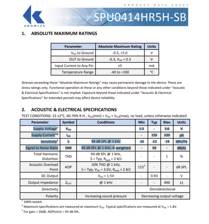
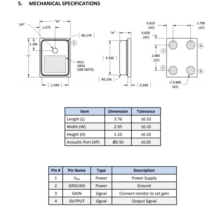
Sound sensor input device
1) SPU0414HR5H-SB MIC for sound sensor specifications and circuit design
- Up to 20dB of Gain
- Maximum supply voltage 3.6V
- Maximum Low Current 220uA
- Signal to Noise Ratio SNR 94 dB SPL @ 1 kHz, A-weighted
- RECOMMENDED REFLOW PROFILE Peak Temperature (TP) 260°C
This specification means I will need to use a voltage regulator with the sensor in order to convert the 5V power to 3.5V
Circuit Components
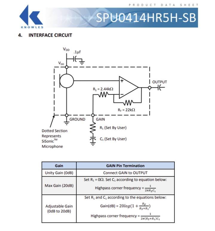
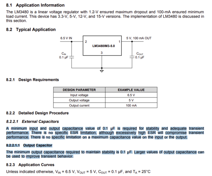
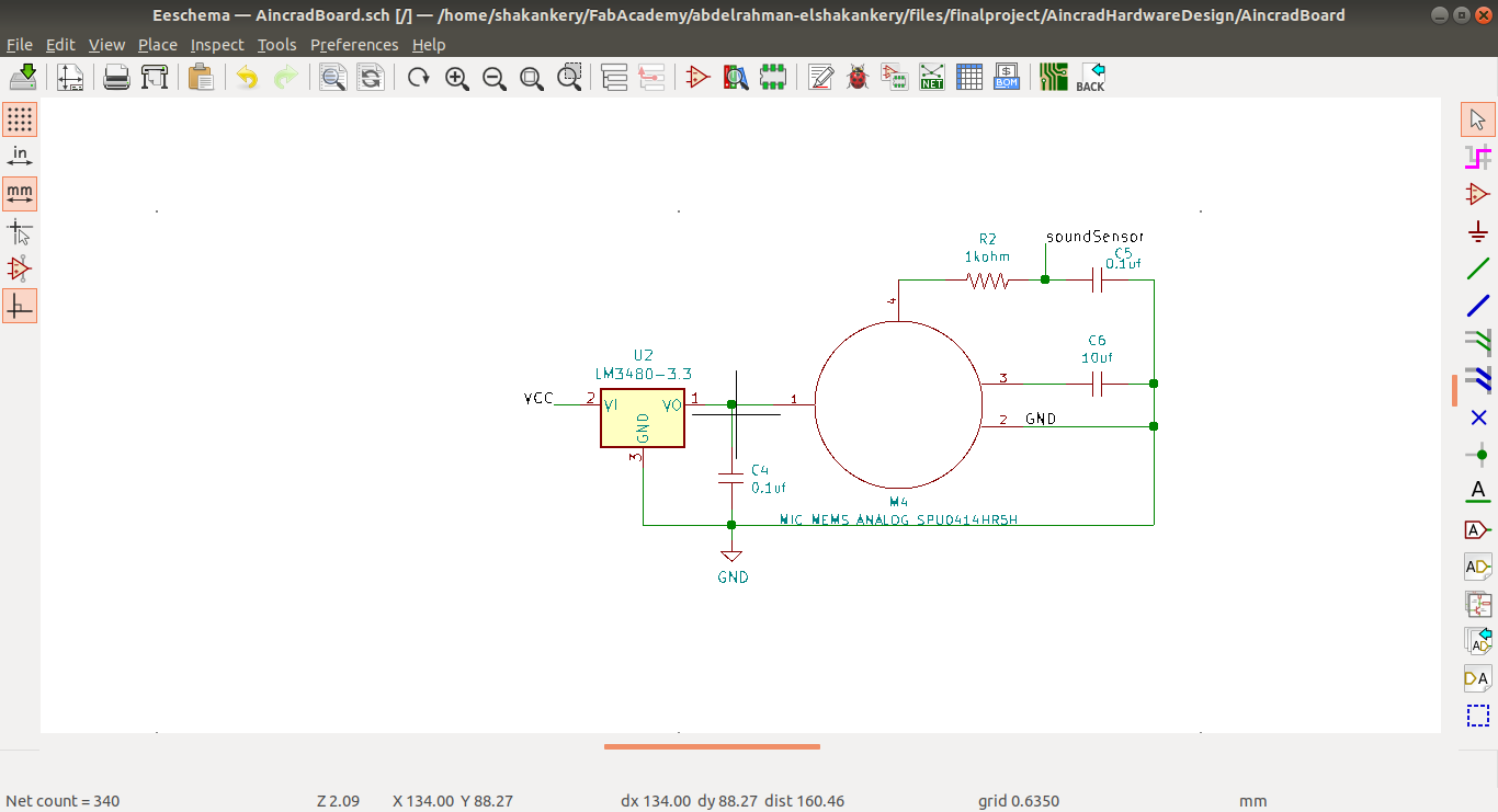
So now in order to design the circuit I need to choose a voltage regulator to convert 5V power to 3.5V I go with LM3480 Low-Dropout Linear Voltage Regulator
LM3480 Linear Voltage Regulator specifications
from the datasheet
- Input Voltage Range: up to 30 V
- 3.3-V, 5-V, 12-V, and 15-V Versions Available
- 100-mA Ensured Minimum Load Current
- SOT-23 Package
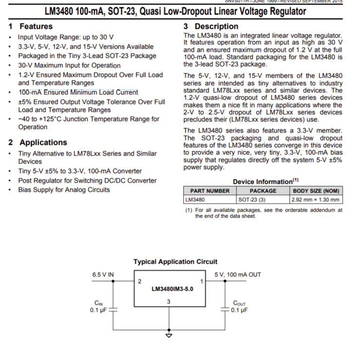
Vout= 4.8-1.5= 3.3V
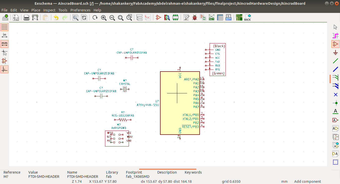
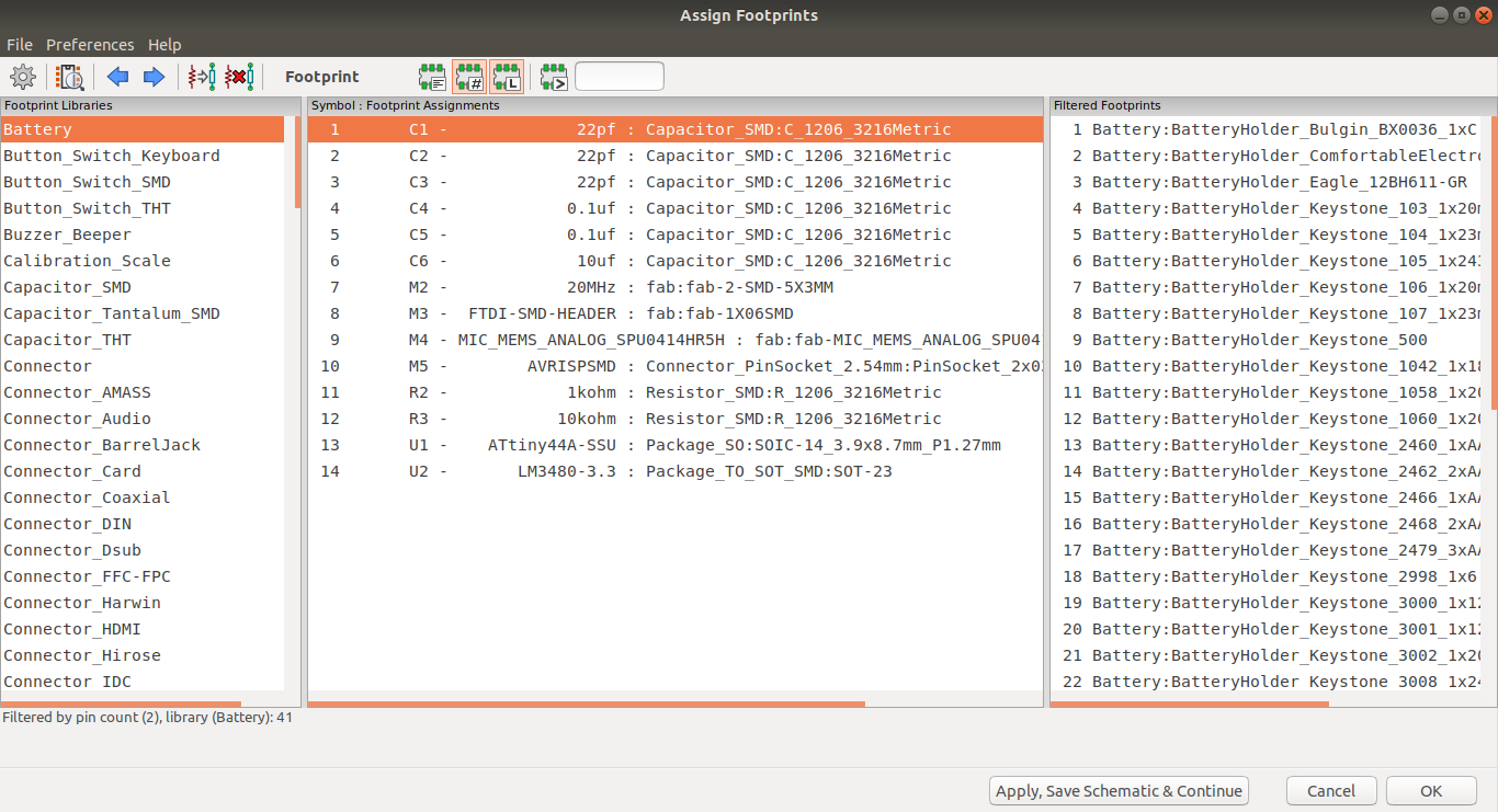
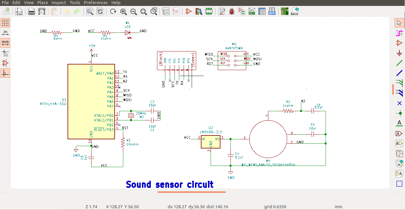
2) Schematic Design using Kicad
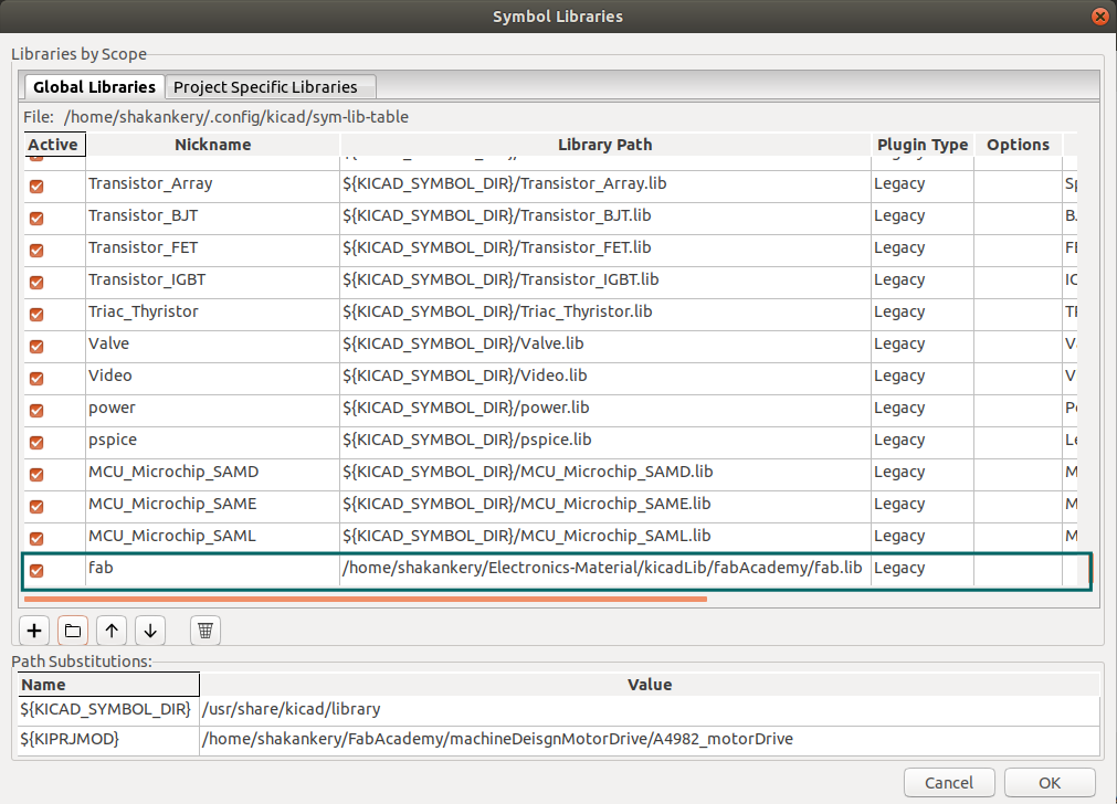
Download Fab-library:
you can find a fab-library with all the inventory component Here. download it then create a folder wherever you want for kicad folder to be kept.
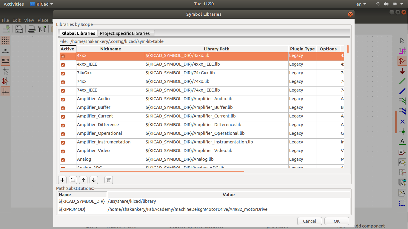
along side that I open our flinc-inventory-sheet to make sure we have the same values of the components I need.
Circuit Components

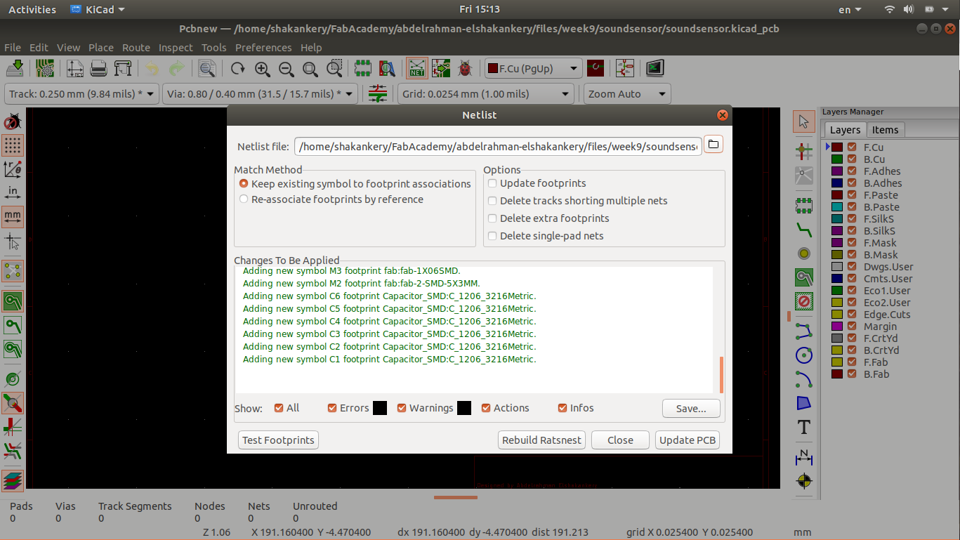
Generating the Netlsit is the final step after finishing all the design.
This step is really important in order to connect the schematic with PCBnew in which we will going
to create
the PCB layout.
Now it's time for the layout design.
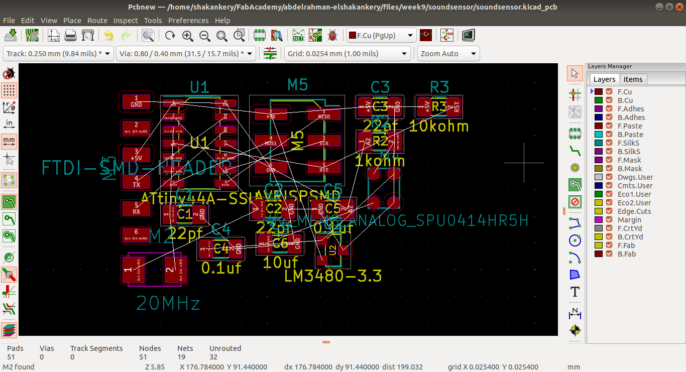
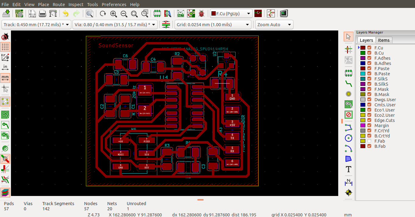
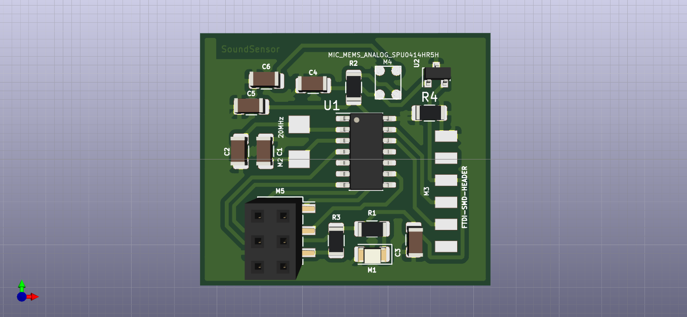
3)PCB layout
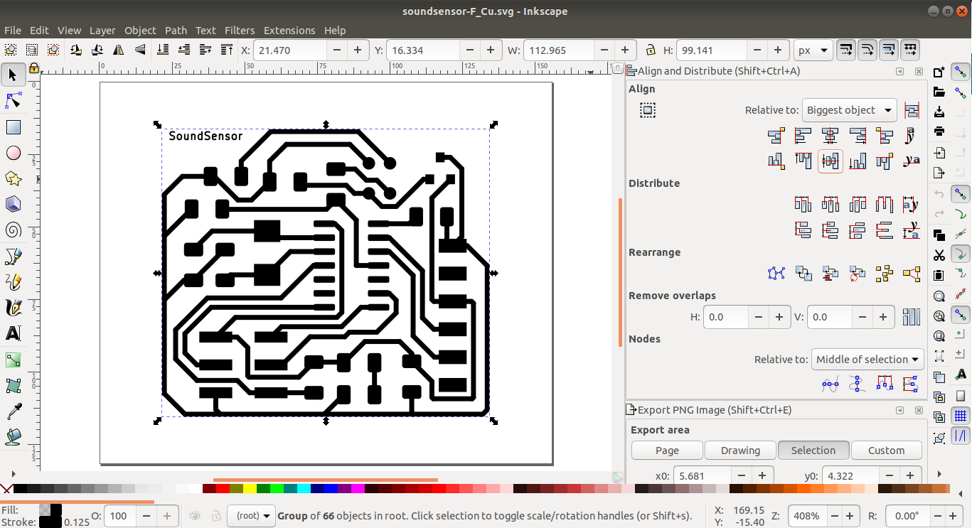
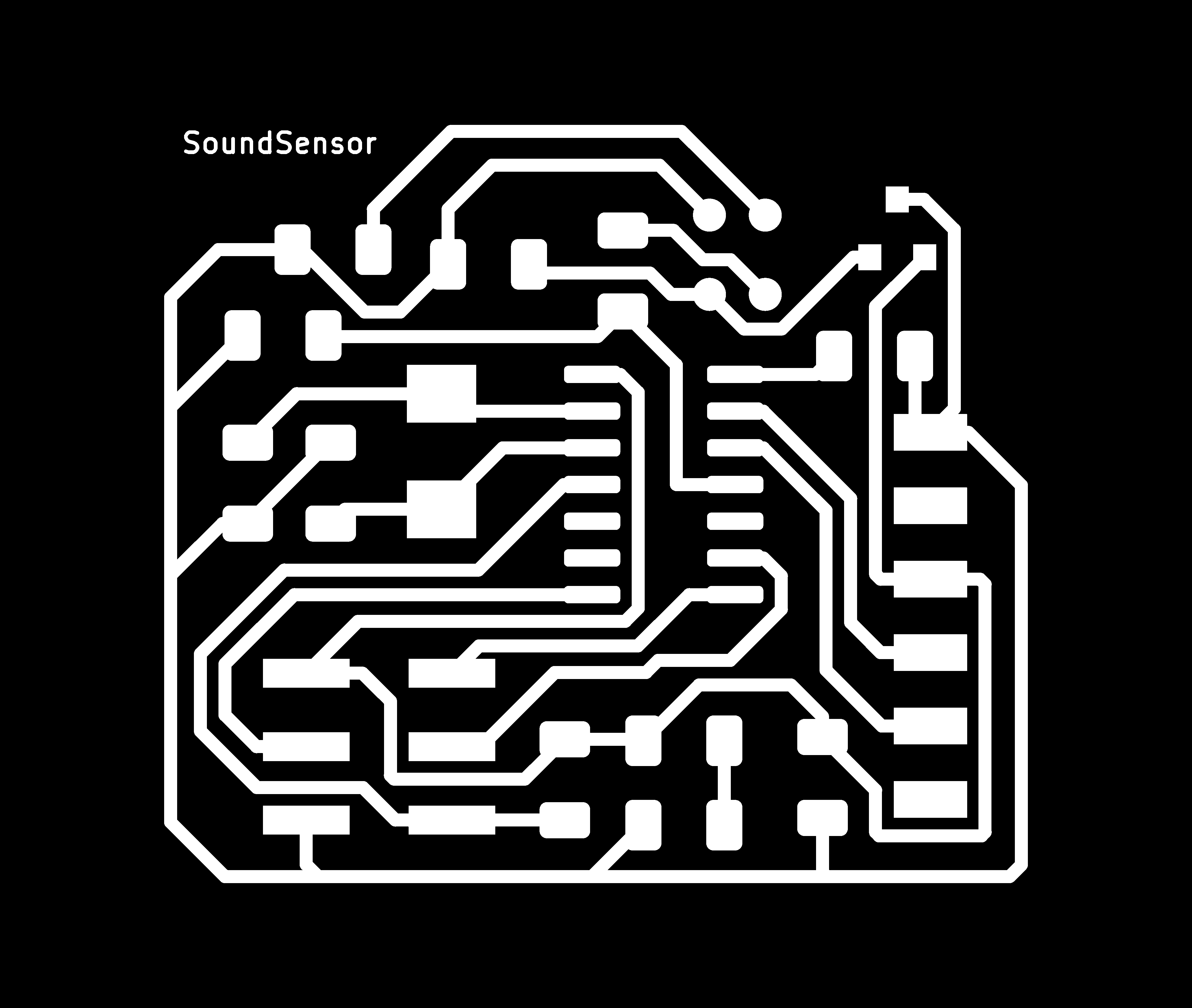
4) Create .png files for mods
unfortunately till now kicad cann't export a .png files so I need to convert the .svg I have got to
.png files.
First I was thinking ok lets use inkscape then I realize something that I'm not only have to convert
the files but also because of how mods expect the outline file,
I need to invert the B&W colors!
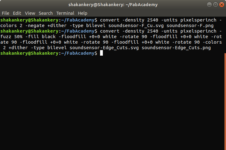
So I decided to use Imagemagick to make an automatic conversion from .svg to .png
so first I alligned the file exactly into the center using Inkscape then I run these 2 commands
through the terminal to make the automatic conversion.
convert -density 2540 -units pixelsperinch -colors 2 -negate +dither -type bilevel soundsensor-F_Cu.svg soundsensor.pngFor the Edge-cut layer "Border"
convert -density 2540 -units pixelsperinch -fuzz 50% -fill black -floodfill +0+0 white -rotate 90 -floodfill +0+0 white -rotate 90 -floodfill +0+0 white -rotate 90 -floodfill +0+0 white -rotate 90 -colors 2 +dither -type bilevel soundsensor-Edge_Cuts.svg soundsensor-Edge_Cuts.png

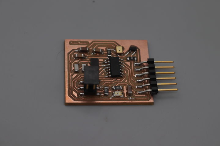
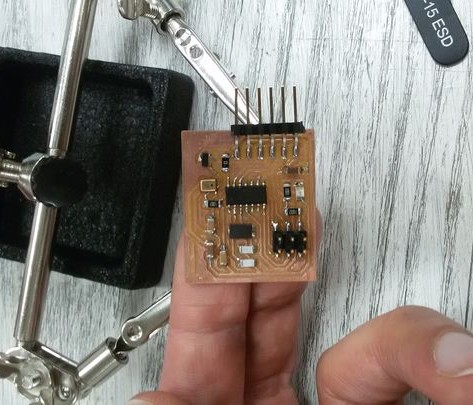
Milling and solder the circuit
following the same steps we did in Electronics production week I was able to solder and mill the circuit.
I started by soldering the mic. it take a lot of time as it wasn't an easy task to do, but at the end I've managed to do it using a hot gun and a twezer.
Testing the circuit
The Code:
Knowing that the Mic output will float at one-half Vcc when there is no sound (all is quiet) and produce a peak-to-peak output about 200mv when talked into. and also remembering that it's a sound signal, so we'll likely want to use the amplitude of the sound wave rather than the raw voltage output.
The Attiny44 analog (ADC-10bit) input converts our audio signal into an integer. The range of possible ADC values is between 0 and 1023, this range so the resolution of our ADC measurement is 1024 and our Voltage is 3.3V.. To convert our analog measurement into a voltage, we use the following equation:

For many applications that deal with sound (which is a wave), we're mostly interested in the
amplitude of the signal. In general, and for the sake of simplicity, a larger amplitude means a
louder sound, and a smaller amplitude means a quieter sound (and the sound wave frequency roughly
corresponds to pitch). Knowing the amplitude of our audio signal allows us to build a sound
visualizer, set a volume threshold trigger, to activate our output board
for example.
For our code:
To find the audio signal amplitude, we take a bunch of measurements in a small time frame (50 ms,
the lowest frequency a human can hear).knowing the minimum and maximum readings in this time frame
and
subtract the two to get the peak-to-peak amplitude. we can use the ADC integer
value, or convert this into voltage as described above.
#include < SoftwareSerial.h >
#define TX 0
#define RX 1
#define soundSensor 2
SoftwareSerial mySerial(RX,TX);

const char sampleTime =50;
byte micOut;
boolean state = true;

void setup() {
  mySerial.begin(9600);
}

void loop(){
   unsigned int micOutput = findPTPAmp();
   mySerial.println(micOutput);
   //test a trigger value of clapping
   /* if (micOutput>=80){
	if(state){
	  mySerial.println("Led oN");
	  state= false;
	  }
	  else {
		mySerial.println("Led off");
		state=true;
	  }
	}*/
}

int findPTPAmp(){
// Time variables to find the peak-to-peak amplitude
   unsigned long startTime= millis();  // Start of sample window
   unsigned int PTPAmp = 0;

// Signal variables to find the peak-to-peak amplitude
   unsigned int maxAmp = 0;
   unsigned int minAmp = 1023;

// Find the max and min of the mic output within the 50 ms timeframe
   while(millis() - startTime < sampleTime)
   {
	  micOut = analogRead(soundSensor);
		if( micOut < 1023) //prevent erroneous readings
		{
		  if (micOut > maxAmp)
		  {
			maxAmp = micOut; //save only the max reading
		  }
		  else if (micOut < minAmp)
		  {
			minAmp = micOut; //save only the min reading
		 }
	   }
	}

PTPAmp = maxAmp - minAmp; // (max amp) - (min amp) = peak-to-peak amplitude
//double micOut_Volts = (PTPAmp * 3.3) / 1024; // Convert ADC into voltage
//Return the PTP amplitude.
return PTPAmp;
}
Final results + Group Assignment
We don't have an oscilloscope in our lap so I will going to use the serial monitor to present the output data from my board, however due to
Covid19 I doing this test from home and I don't have a FTDI-cable to send the
signal.
so I upload a Blink code to my arduino then I've conected the TX,Rx of the sound sensor to the TX,RX
of the arduino.