Week 4- Electronics Production
Overview
For this week we have two assignments:
- Group assignment
- Individual assignment
Characterize the design rules for your PCB production process: document feeds, speeds, plunge rate, depth of cut (traces and outline) and tooling.
Make an in-circuit programmer by milling and stuffing the PCB, test it, then optionally try other PCB fabrication process.
At the beginning we start by machine charactrization as a group then I start working on my assignment using fab-modules & Roland SRM-20.
My Assignment Steps:
Step (1):Mill, stuff and solder the board.
Step (2):Test the board and document that it's functional.
The Process
Individual Assignments
I'm an elctronics engineer so for this week it was a comfort zone for me. However it has been a long time since I've developded any PCBs so I'm really excited to go back on track :).
Know your Machine
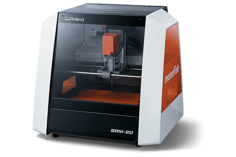
Roland SRM-20 MonoFab is a small milling machine that capable of 3D milling, 2D Milling, and Engraving. The SRM-20 is ideal for a variety of product designs tasks such as model making, create realistic 3D prototypes and rapid prototyping.
- Roland SRM-20 Technical Specs:
- Material: Modeling Wax, Chemical Wood, Foam, Acrylic, Poly acetate, ABS, PC board
- Work area: 203.2 (X) x 152.4 (Y) x 60.5 (Z) mm
- Distance From Collet Tip to Table: Maximum->(130.75mm)
- Max Tool Size: 6mm
- Spindle Speed: 3000-7000 rpm
- Operating Speed: 30mm/sec
- Computer Interface: USB
- Power: 110V / 2.5A
Mill the Board (FabModules)
Choose the right PCB sheet "FR1"
However FR4 is the most common and popular among PCB using material it made out of fiber glass which is not suitable for milling process, so we make sure to choose a good FR1 sheet and clean it before we start.
Use double tape to secure the board on-top of the sacrificial plate
make sure there is no overlapping in double tape and there is no air bubble.
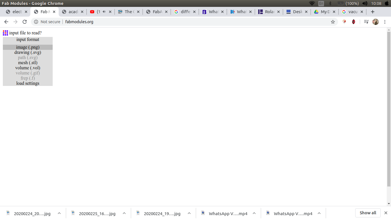
open fabmodules then choose the input to be an image.png

choose the output to be RML
For the process choose either traces or outline
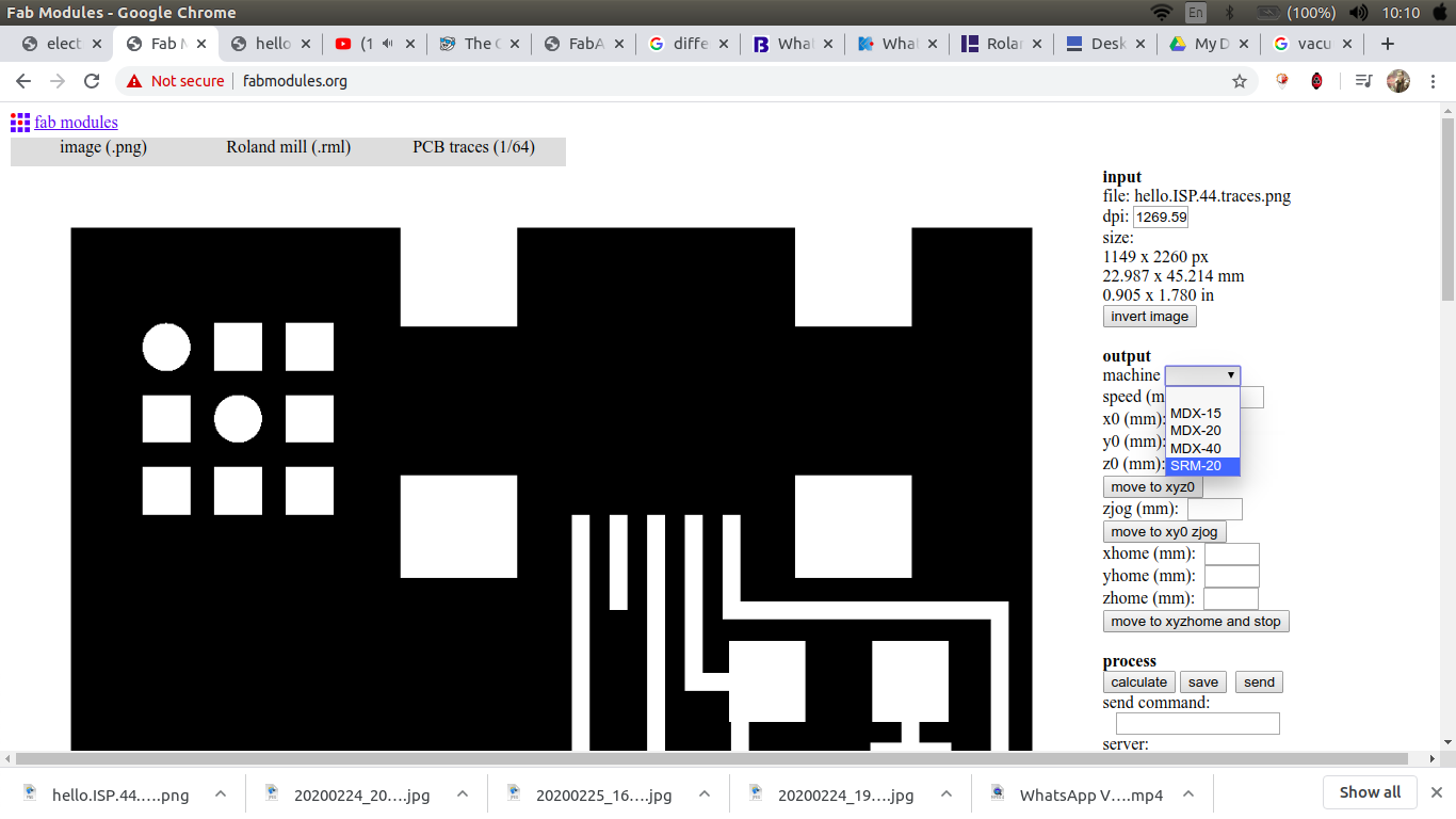
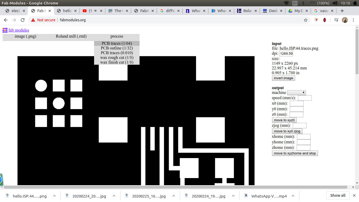
choose the machine, zero XYZ, choose no.of offset and the cut depth
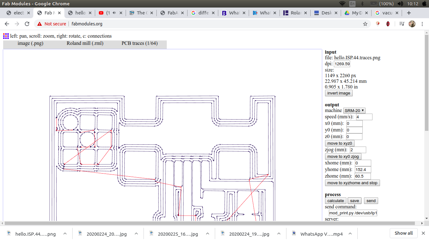
calculate then save.
we use v-tip 30degree*0.2 in the traces and 0.1 endmill in cutting outlines
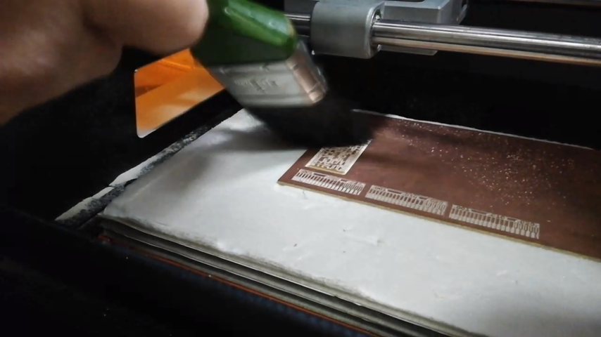
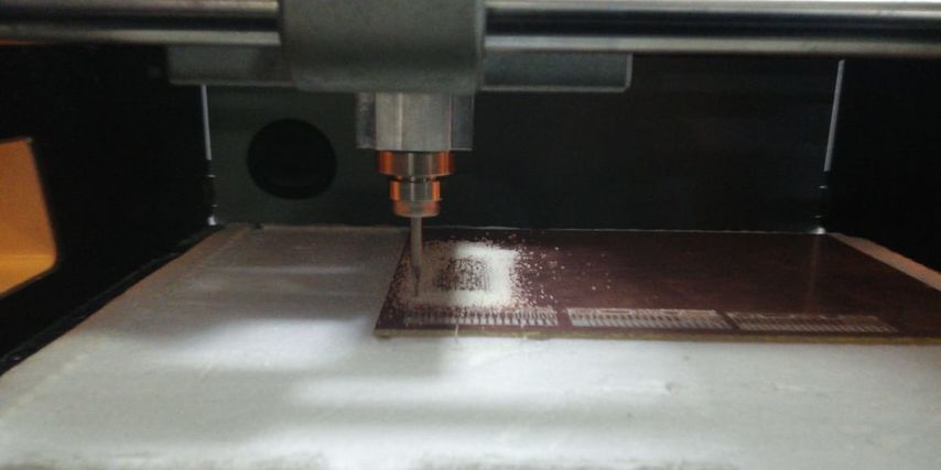
make sure to clean the board using only vacuum cleaner or a bruch
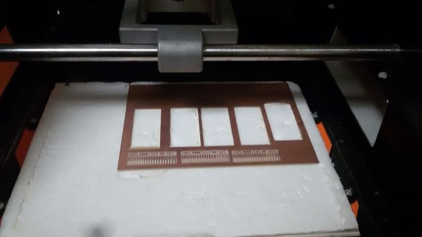
my whole team is going to mill the same circuit so in order to save time and effort we mill the traces for the four of us at first then cut the outline for each circuit .
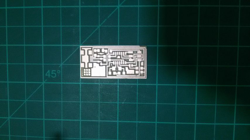
final output.
Solder the board (let's be serious)
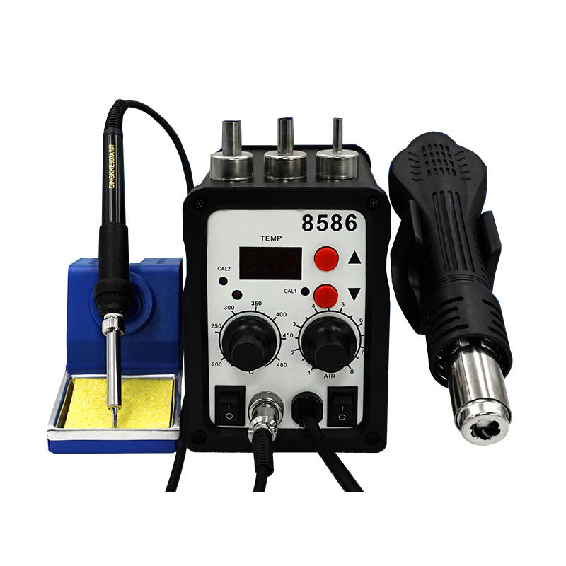
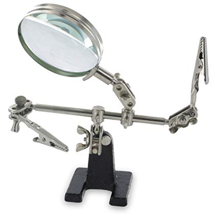
for SMD soldering you will need:
fortunately for me we have a solder station in our lab so I only need steady hand and patience :)) .
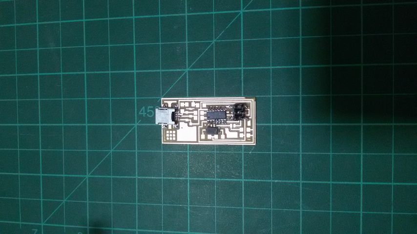
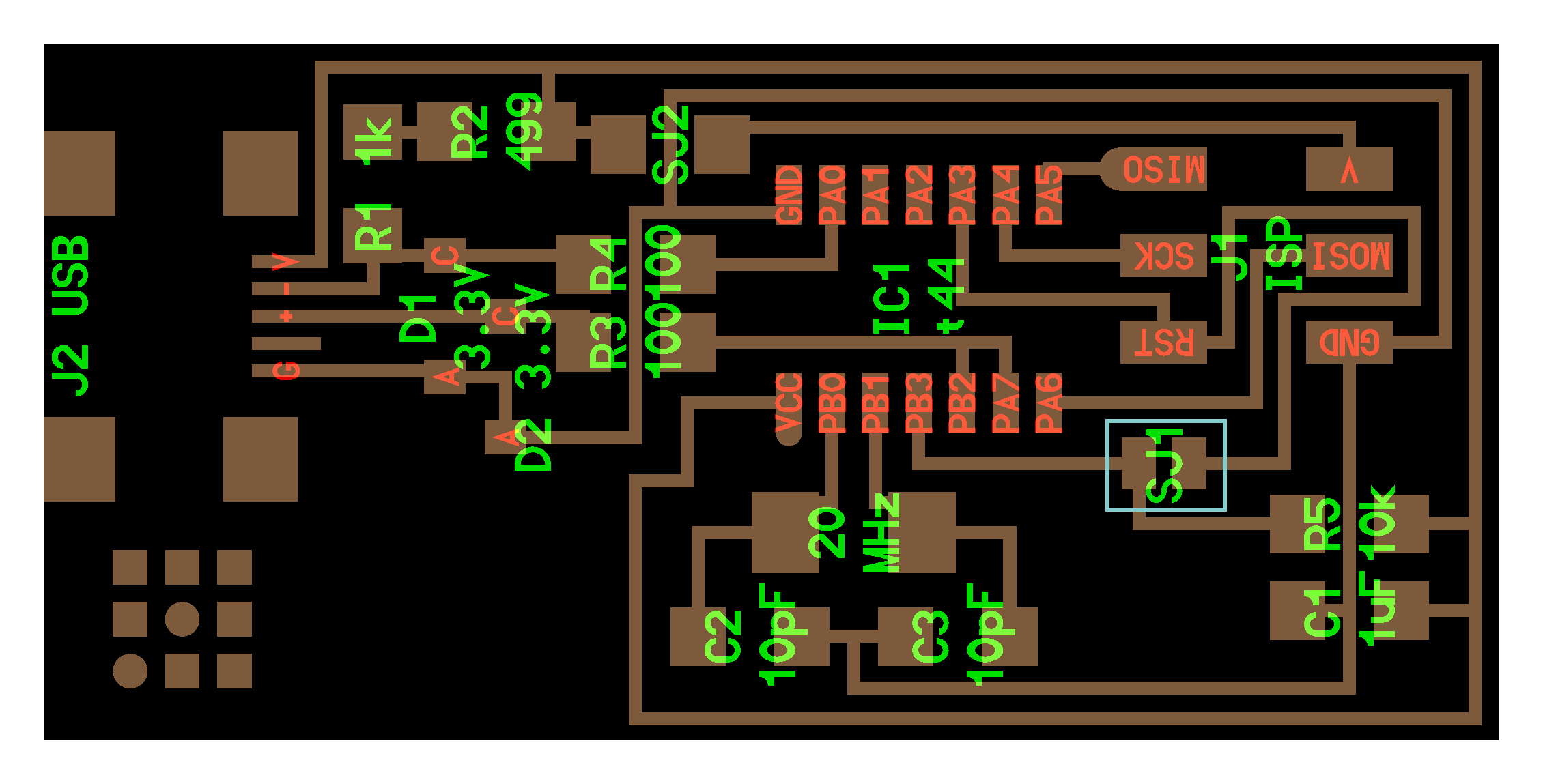
Board components:
Test the board
it's recommended for this step to use linux operating system, however if you're usign windows please make sure all the required precautions before you start.
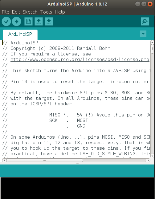
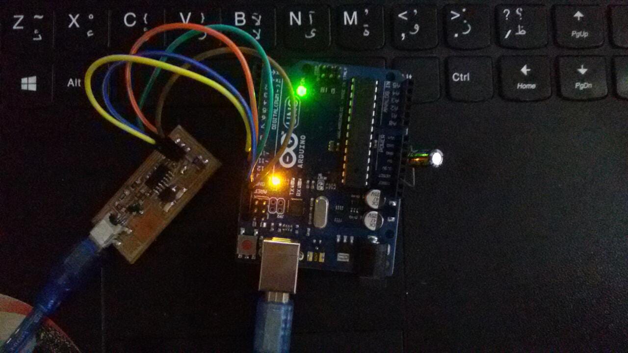
For programming the board you will a programmer of course so you can use either a working FabIsp or an Arduino board. we don't have a working ISP so I go for Arduino.
I follow Neil tuttorial for FabIsp programming ,but as I said I used an arduino so is that the case with you please make sure to check How to use arduino as ISP
The steps
1) Make sure to solder the SJ1 jumpers before you start
2) Install the necessary software for your operating system and download the firmware.
sudo apt-get install flex byacc bison gcc libusb-dev avrdudethen
sudo apt-get install gcc-avrtype y when asked then
sudo apt-get install avr-libcthen
sudo apt-get install libc6-dev
wget http://academy.cba.mit.edu/classes/embedded_programming/firmware.zipUnzip the firmware
unzip firmware.zip
3) Prepare the arduino to work as ISP
 slave reset: 10
 MOSI:        11
 MISO:        12
 SCK:         13
4) Edit the Make configuration
The Makefile is in the firmware directory that you downloaded. The Makefile is set up to work with the AVRISP2 by default. in our case we use arduino, so we will need to edit the Makefile.
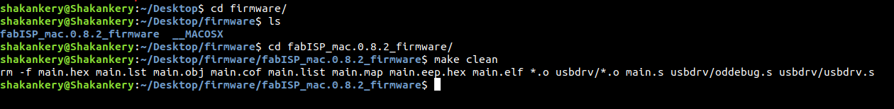
open the terminal then go to firmware directory
nano Makefile
A window will open containing the Makefile. Go to the line that says:
AVRDUDE = avrdude -c avrisp2 -P usb -p $(DEVICE) # edit this line for your programmerthen change it to
AVRDUDE = avrdude -c stk500v1 -b19200 -P /dev/ttyACM0 -p $(DEVICE)
please note that /dev/ttyACM0 is my arduino port so make sure to check which port your arduino connected to under Tools>Port Then substitute /dev/ttyACM0 with your specific port.
5) Program the FabIsp
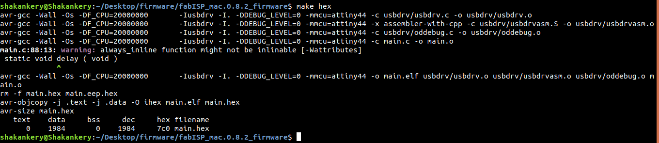
Navigate to the directory where you saved the FabISP firmware. open terminal and let's start compiling the firmware.
make clean
make hex
make fuse

make program
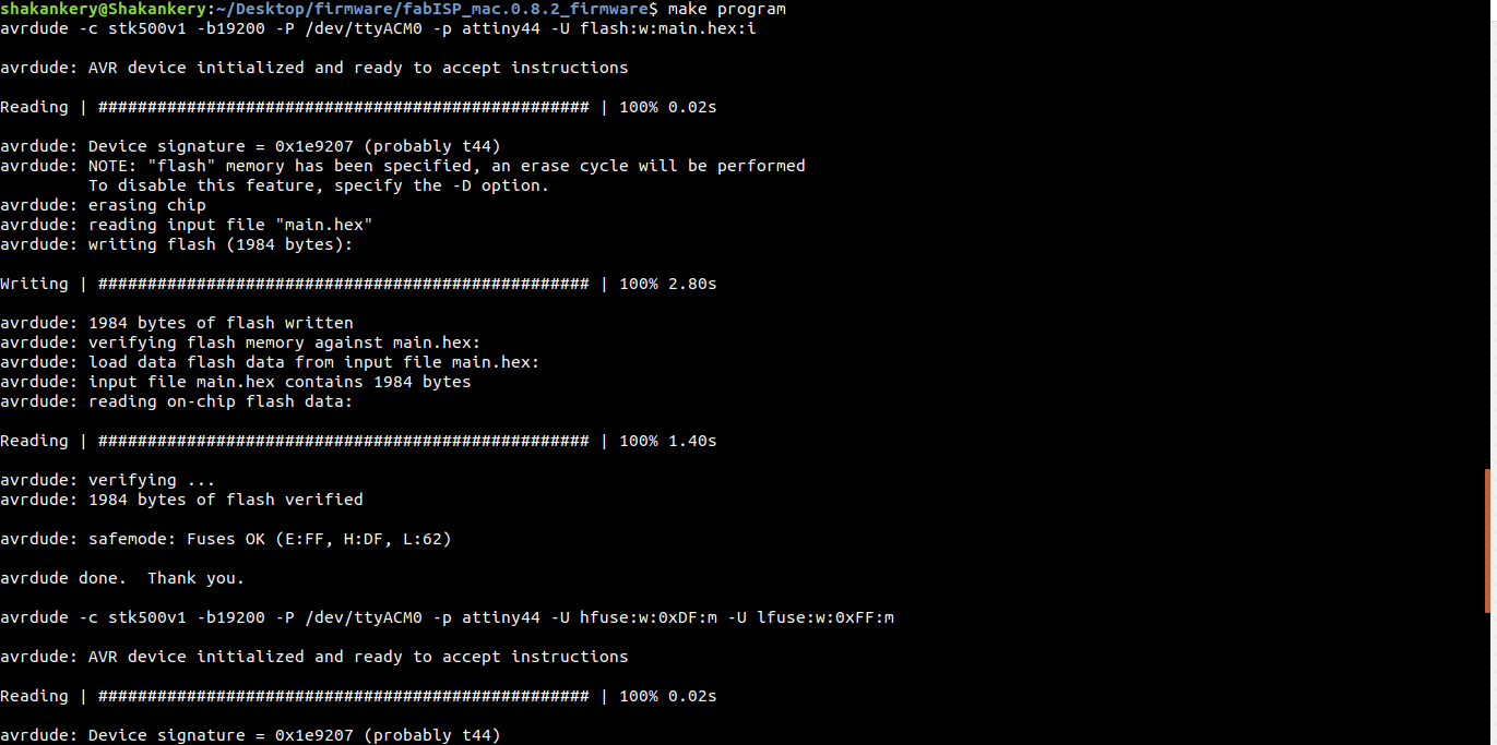
Woow we did it =) ,
6) Our final steps
Remove the 0 ohm resistor or your solder bridge in SJ1. Now you can use it as a programmer to program other boards.
Group Assignment
Please find our work on our group page Fab Lab New Cairo.