Machine Design
Heeeyyyy lovely people, welcome to our final week group assignment. It's machine time
Y'all ;D.
For this week we held an online meeting and started dicussing alot of serious ideas but as we were talking
our instructor notised that our spirits were somewhat down due to all the craziness that's been happening in
the world. She inturrupted us: "Hey guys wait a minute! Our machine does not have to be all that serious,
You know?! Why don't we do some fun machine ?!"
Hearing that we were like: "Oh my God we should!", "I totally agree with you!", "Why haven't we thought
about that!"
So, the tone of the online meeting changed dramatically and got much more exciting.
Discussing fun machine ideas was so much fun itself, We came across that video ,
we held a vote and that was it:
a machine that decorates eggs.
Approach
Having settled on that idea we started organizing our work:
1- We gave ourselves some time to search and scheduled the next meeting to discuss each one's findings.
2- We held a really fruitful meeting discussing all sorts of findings then we listed work to be done and
assigned roles.
Abdelrahman:Team leader, Electronics design & documentation.
Ishaq: Mechanical parts design.
Mansour: Mechanical parts design.
Fathiyah: Coding & *grbl*.
Row'a: Simulation and documentation.
Now let's talk work! 😎
=======
3- We then set several check points and mile stones to check on our progress.
4- We were keen on sticking to the golden rule saying "Document as you go." as much as we could.
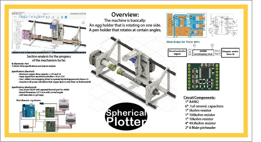
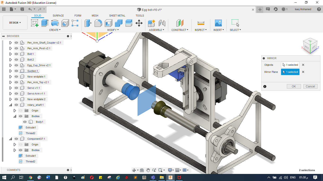
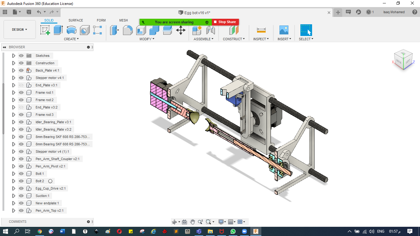
Overview:
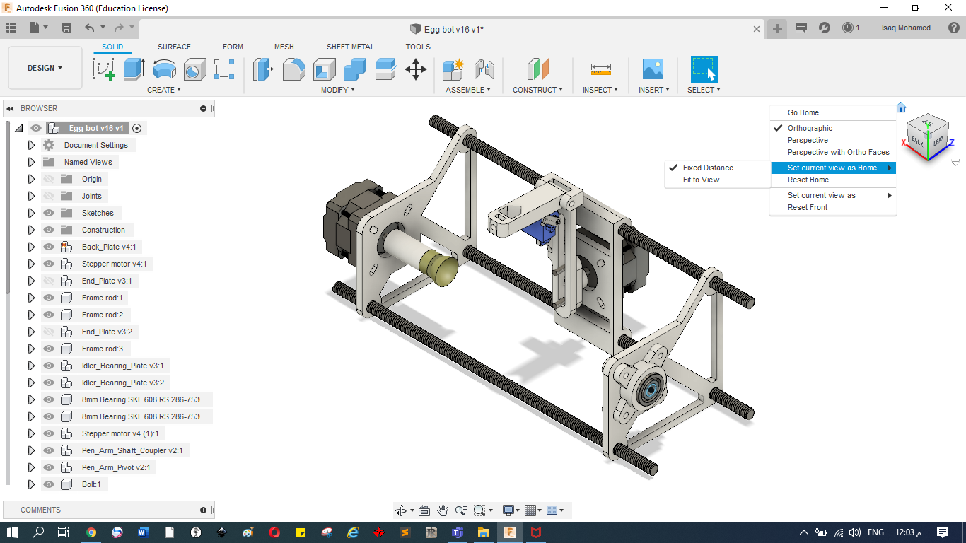
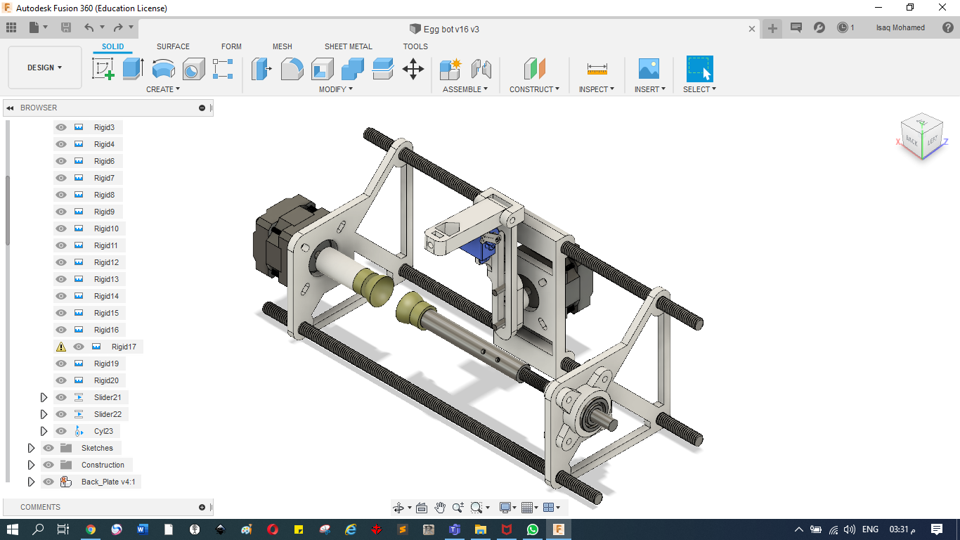
The machine is basically:
An egg holder that is rotating on one side.
A pen holder that rotates at certain angles.
Now let's talk work!
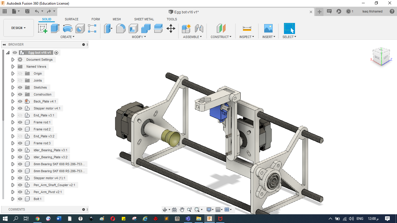
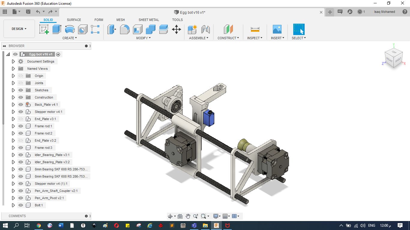
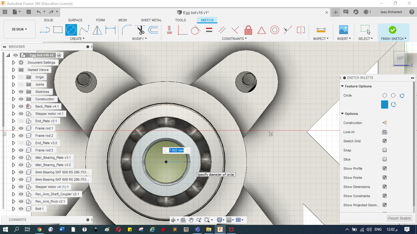
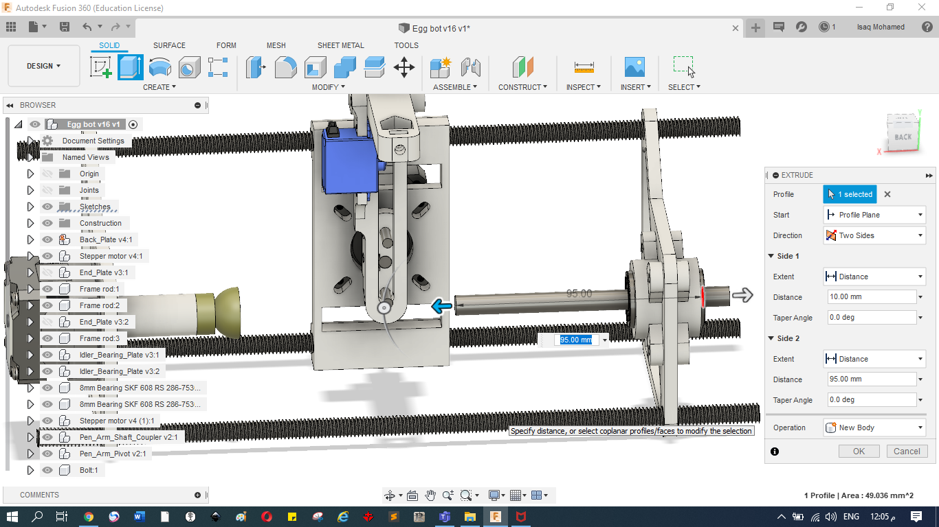
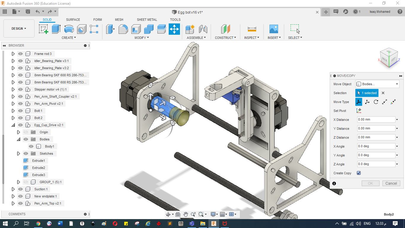
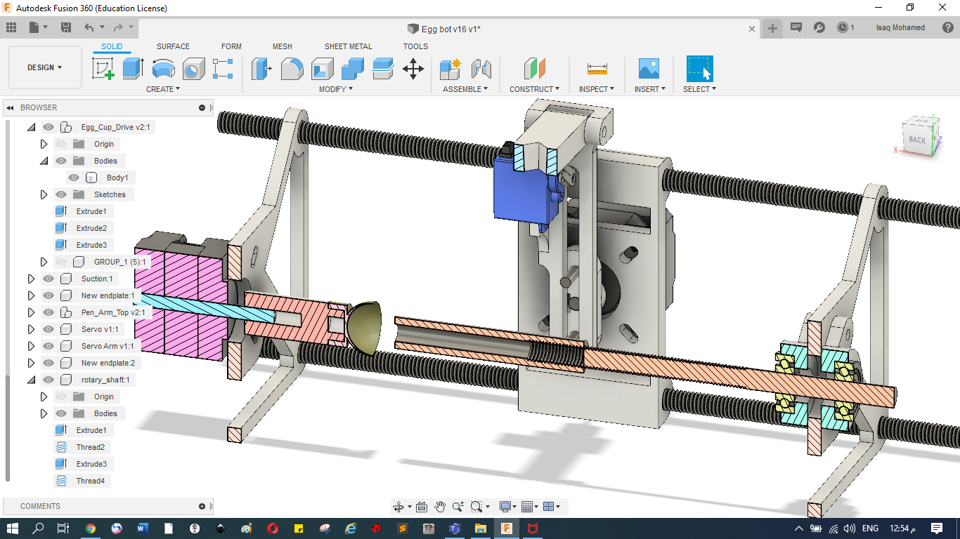
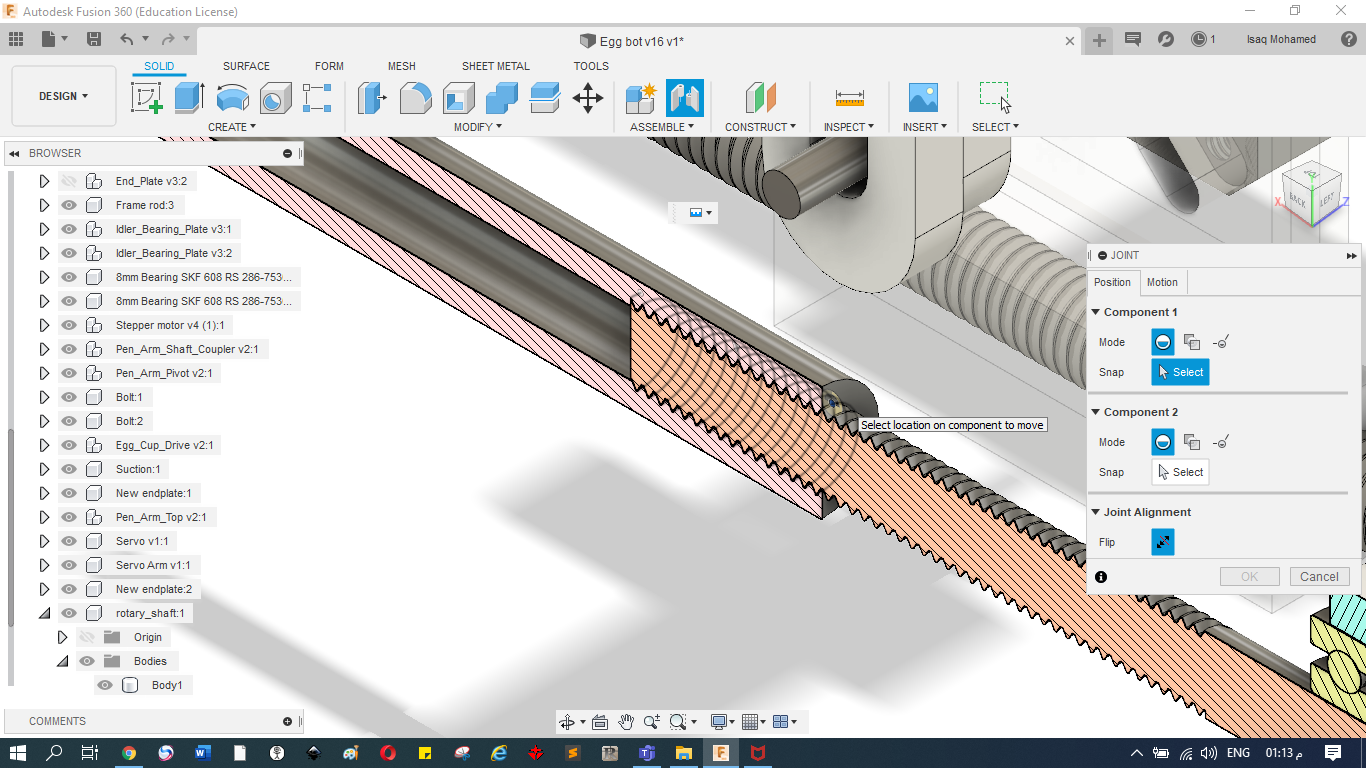
A) Mechanical Part
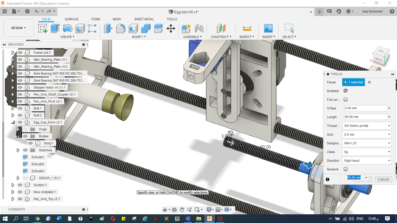
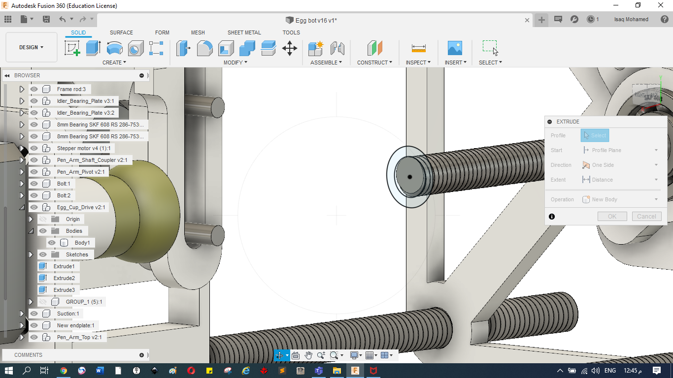
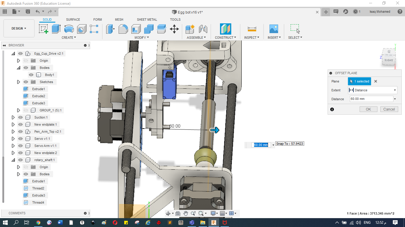
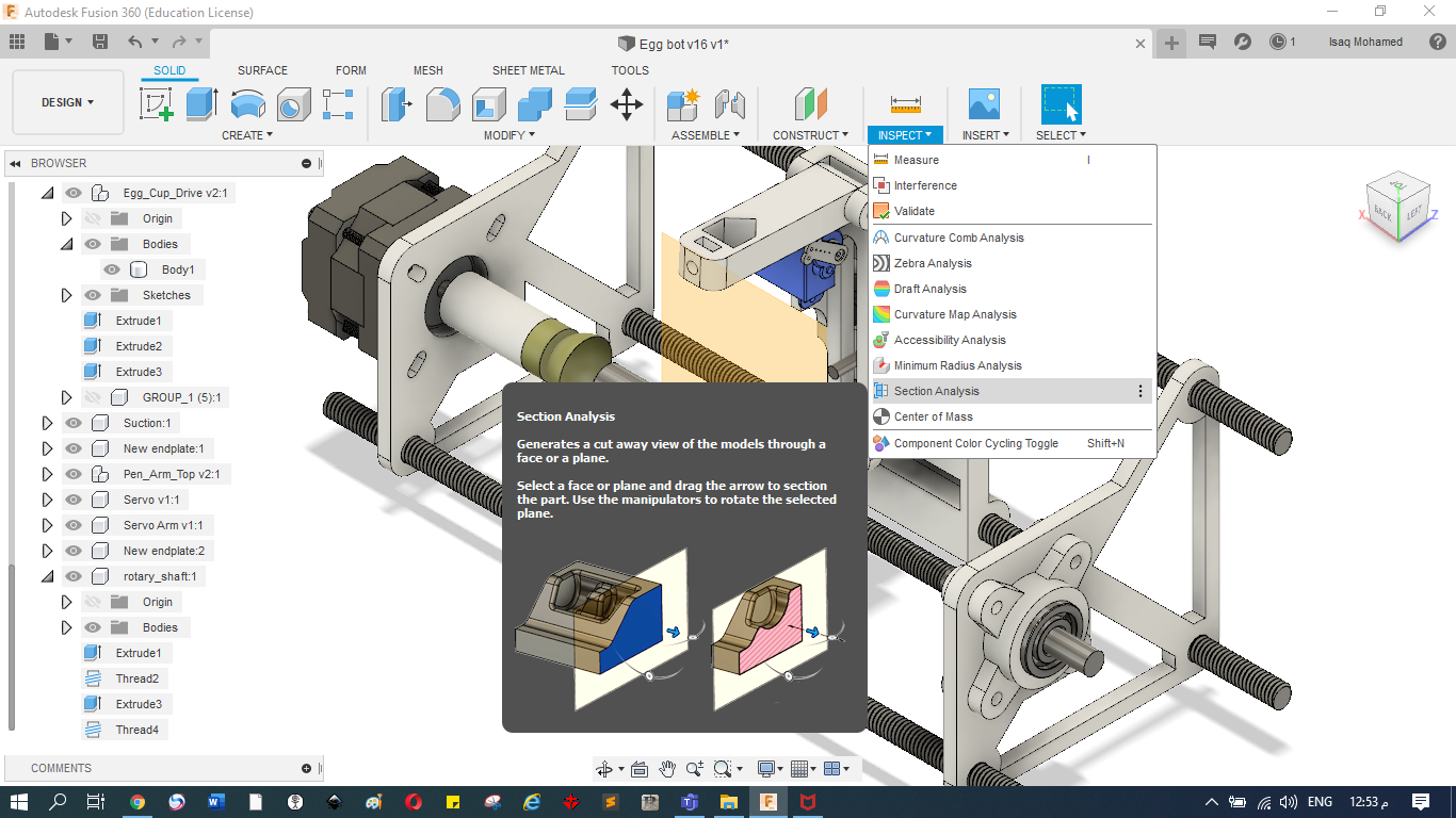
Despite the fact that this machine is open source, the full design was not provided. So that it was a really good chance to do some work on the design and to get to complete it ourselves. The part we had missing was the right hand side egg support and the mechanism to loosen / tighten it.
Files
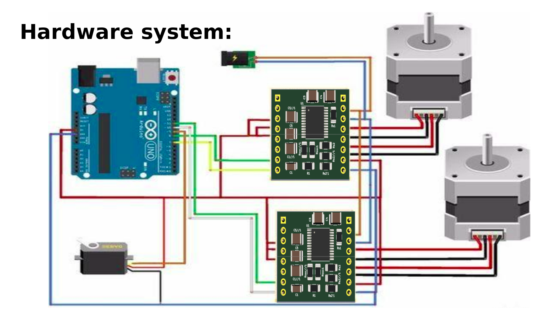
B) Electronics Part
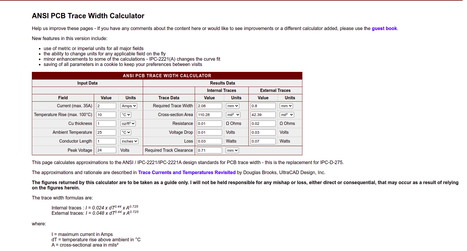
1) Motor drive specifications and system analysis
Specifications (Electrical)
- Minimum output drive capacity = 12V and 1A.
- Input signal from any Microcontroller = 5V or 3.3V
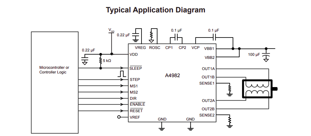
- Use 1 A4982 microstepping driver to operate bipolarsteppermotor Nema-16
- Assume in all power calculation that copper layer is only “1 oz thickness”
Specifications (Mechanical)
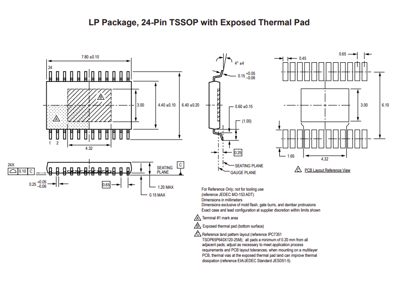
- Use 24-pin TSSOP with exposed thermal pad For A4982
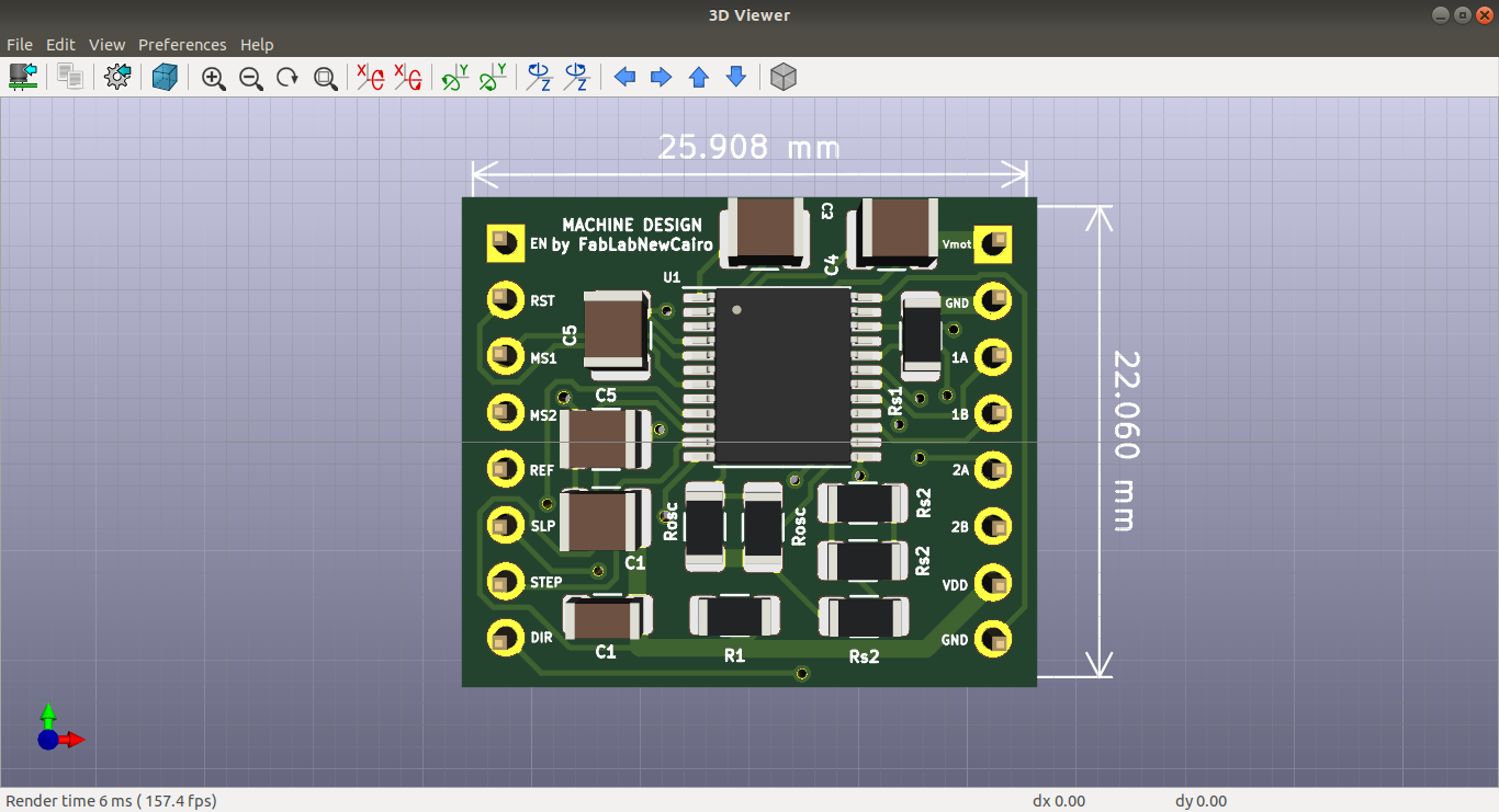
- Board dimensions 2.5*1.5cm with curved angels
- Add heat sinks in pcb layer.
2) Block Design

3) Circuit Design
your number one friend through this step is the datasheet. so let's have a quick tour in A4982 datasheet
A4982 Specifications
Circuit Components
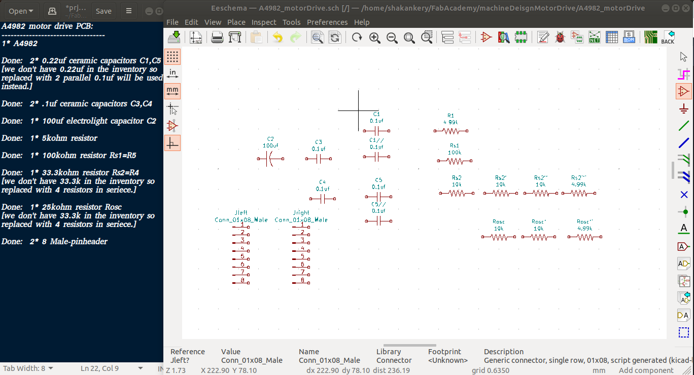
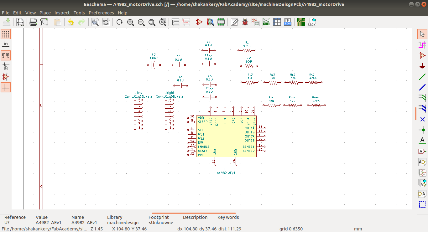
4) Schematic Design using Kicad
Symbols:
add symbols to the sheet and create symbol if needed
along side that I open our flinc-inventory-sheet to make sure we have the same values of the components I need.
we don't have all the components that I need so I tweak the design a little and updated the text file.
Circuit Components
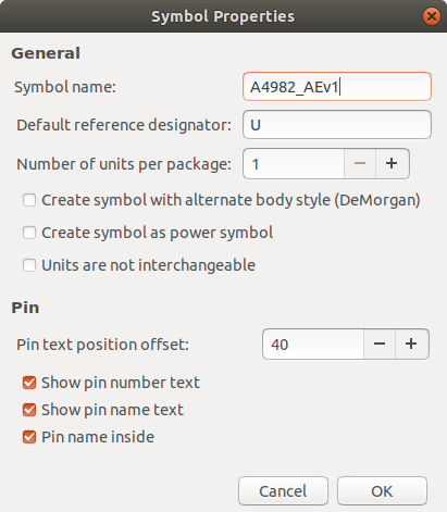
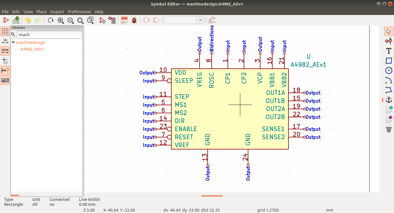
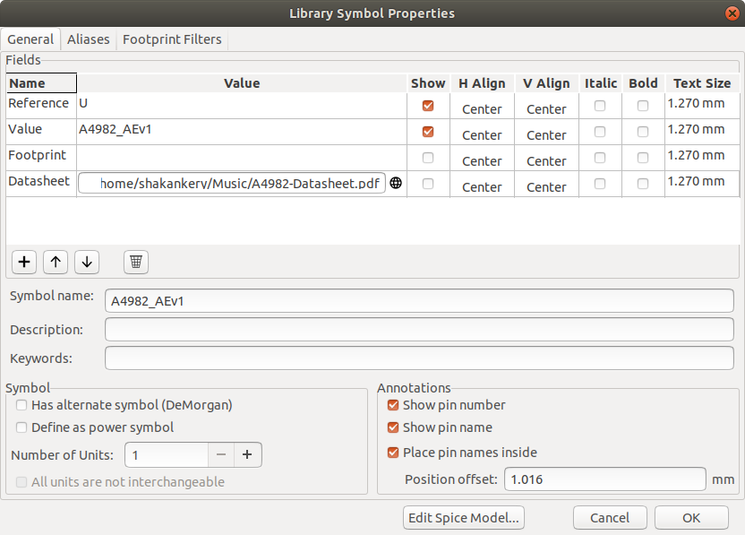
Create A4982 library
from Kicad I choose symbol editor then I create a new library called machineDesign and select the symbol properties to give our symbol it's identity
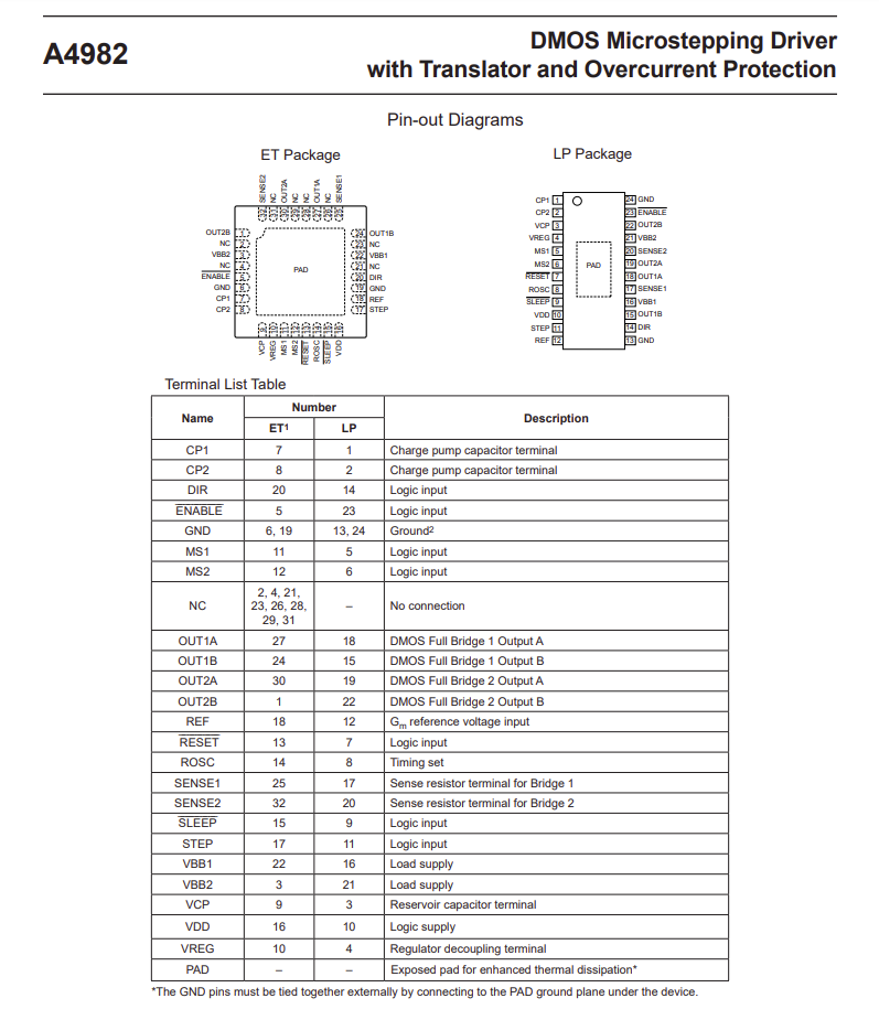
we go back to the data sheet to get the pinout assignment in order to create our A4982 symbol
please find this Reference designator-wikipedia as a reference
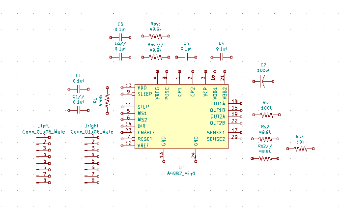
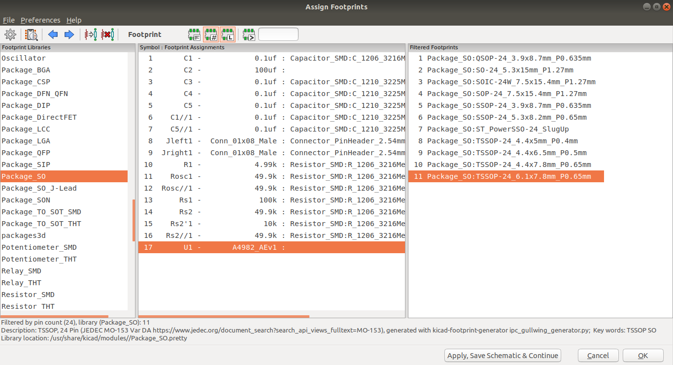
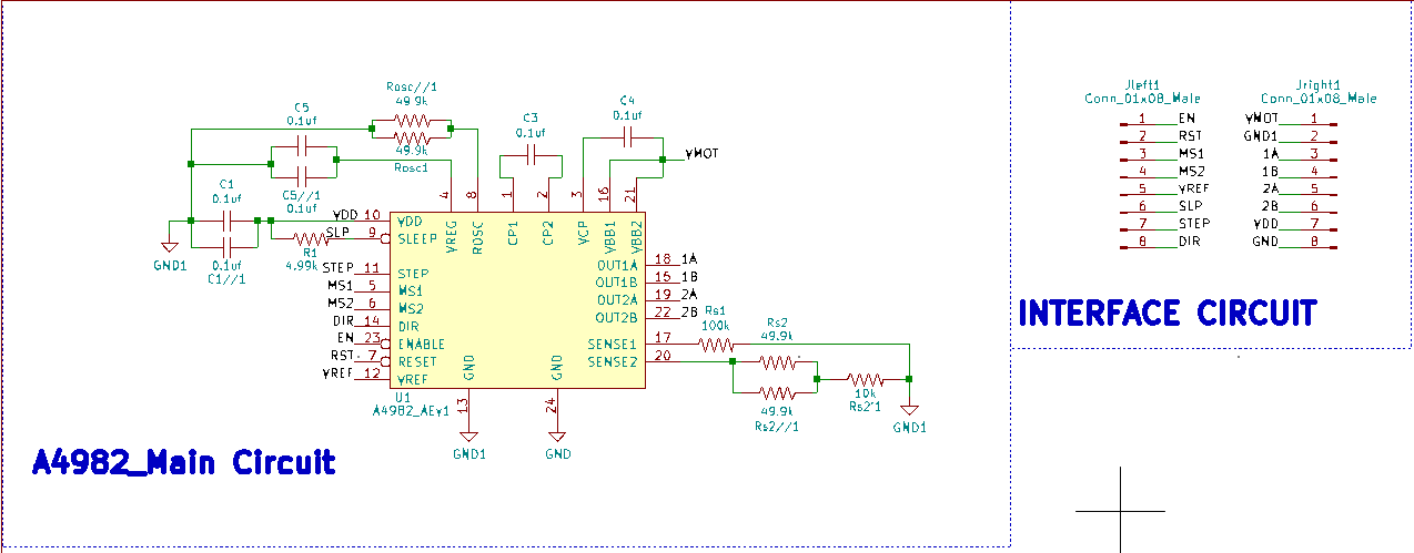
Arrange, Annotate, Associate:
arrange, annotate symbols and associate with footprints
Circuit Components final
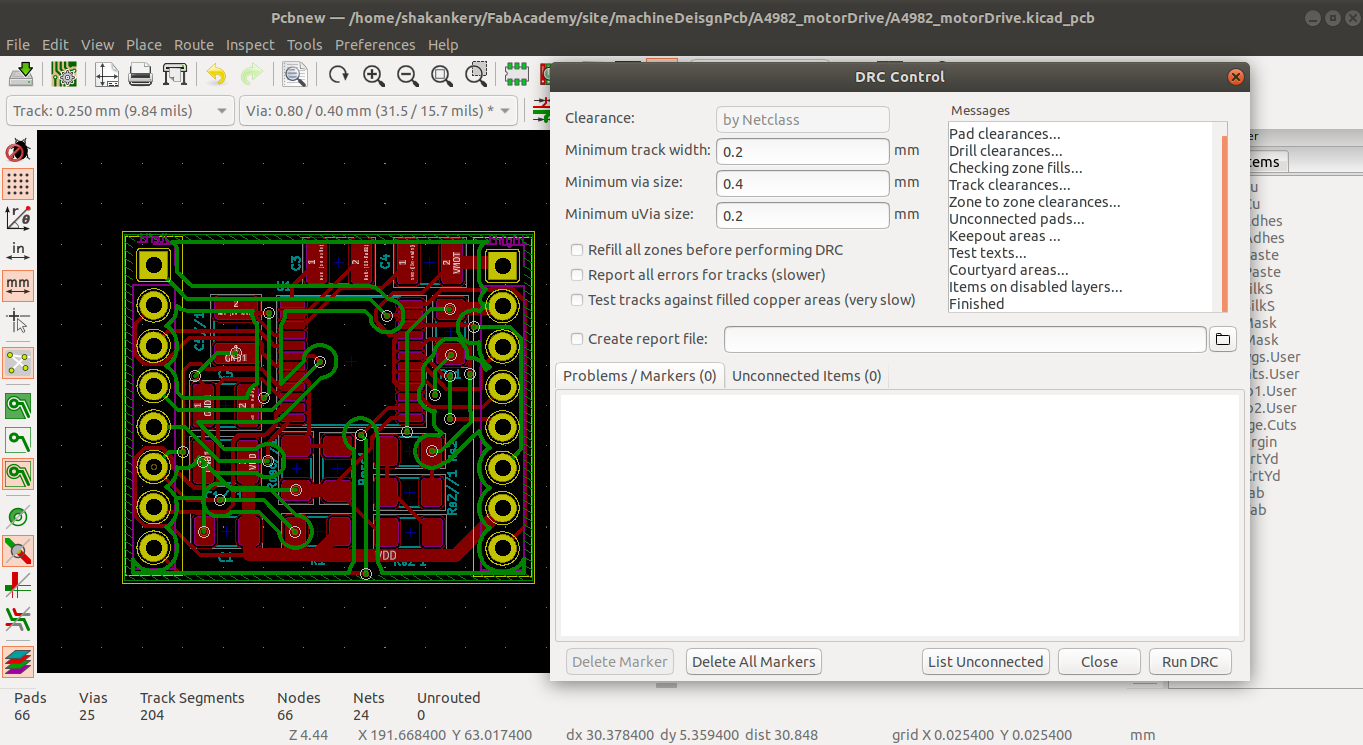
Wiring, Nets, Electrical Rules Check, Comments and Netlist
generator:
final steps and edits to the schematic
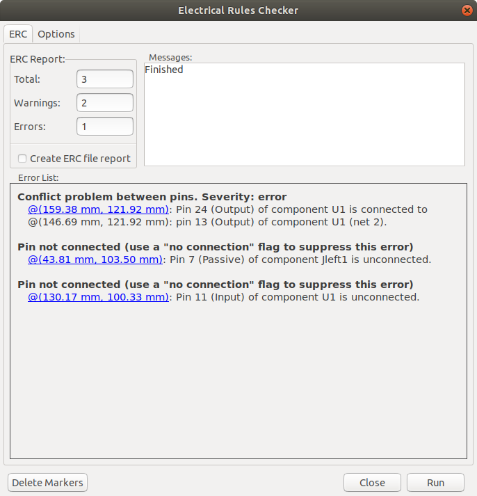
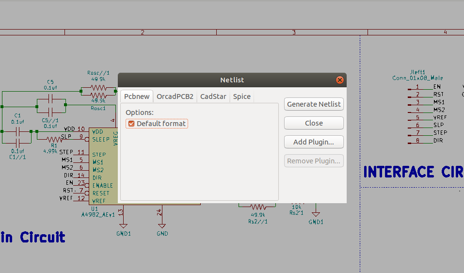
This step is really important in order to connect the schematic with PCBnew in which we will going to create the PCB layout.
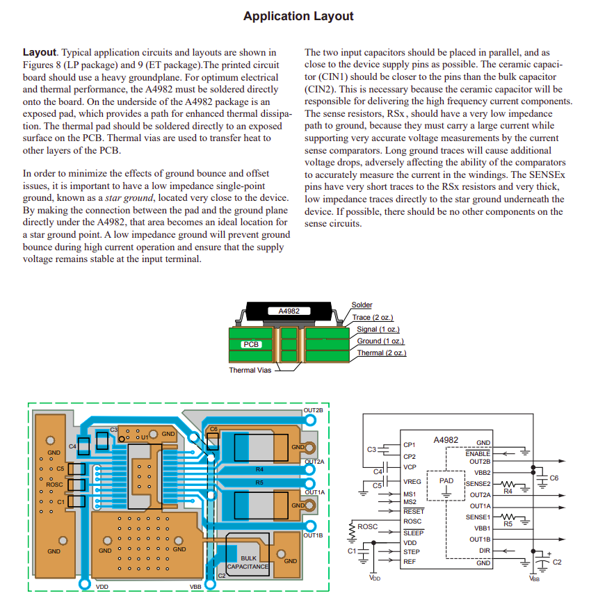
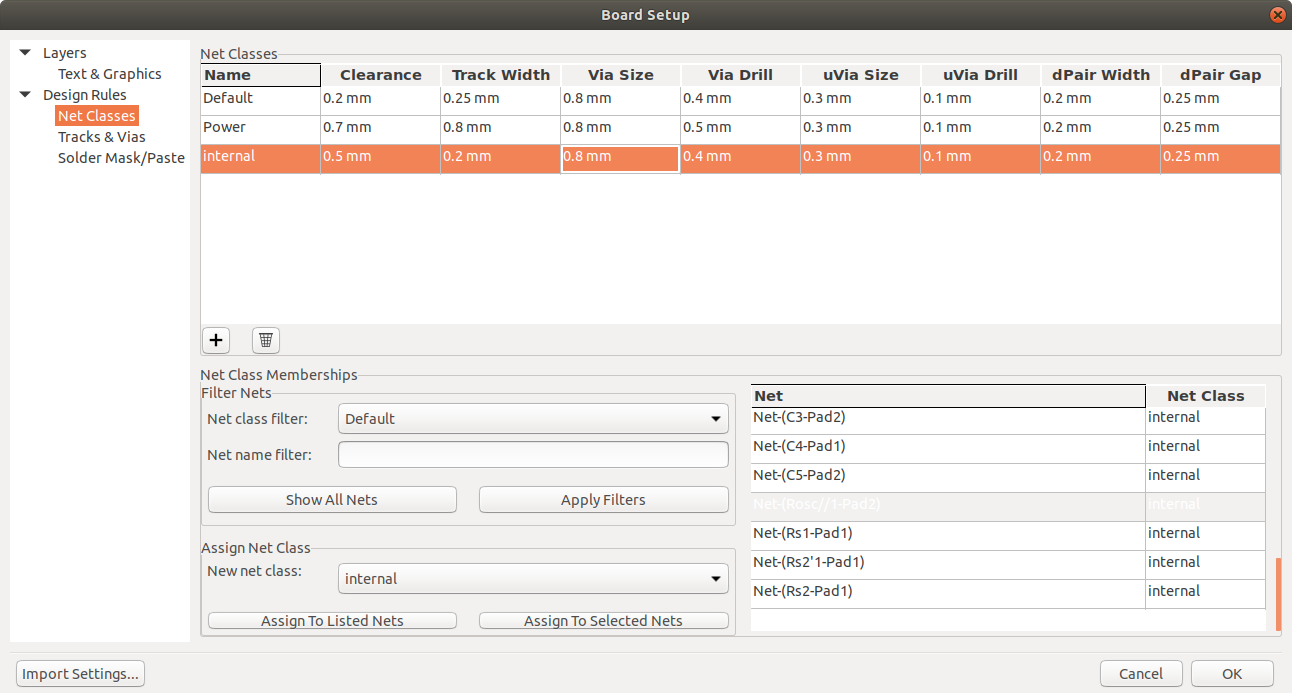
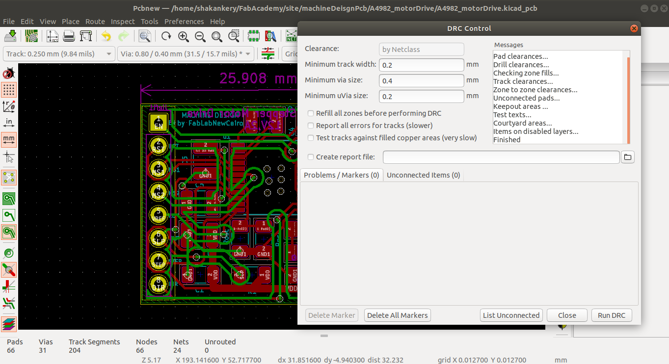
5)PCB layout
Page setup:
add the design information and the schematic Grid setting
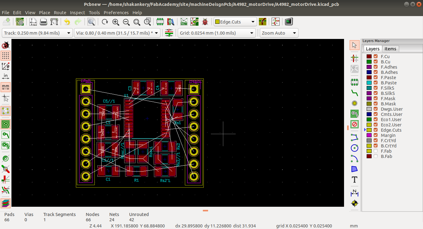
Board Outlines + Component placment:
define the size and shape of the board , arrange the components in functional group starting with
user
interface
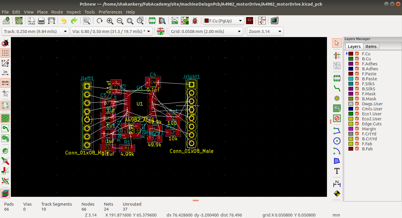
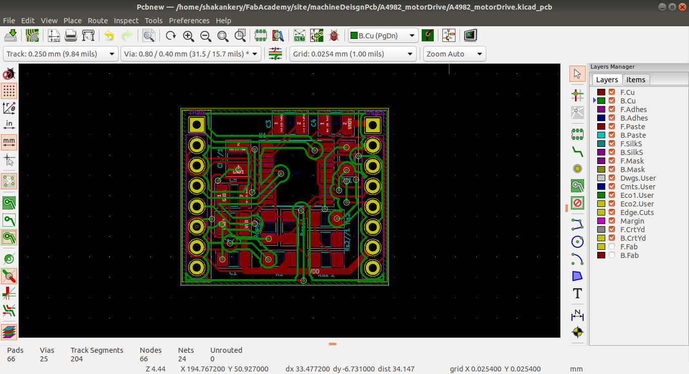
Routing, Copper fills:
routing the component starting with powerthen create a GND fill
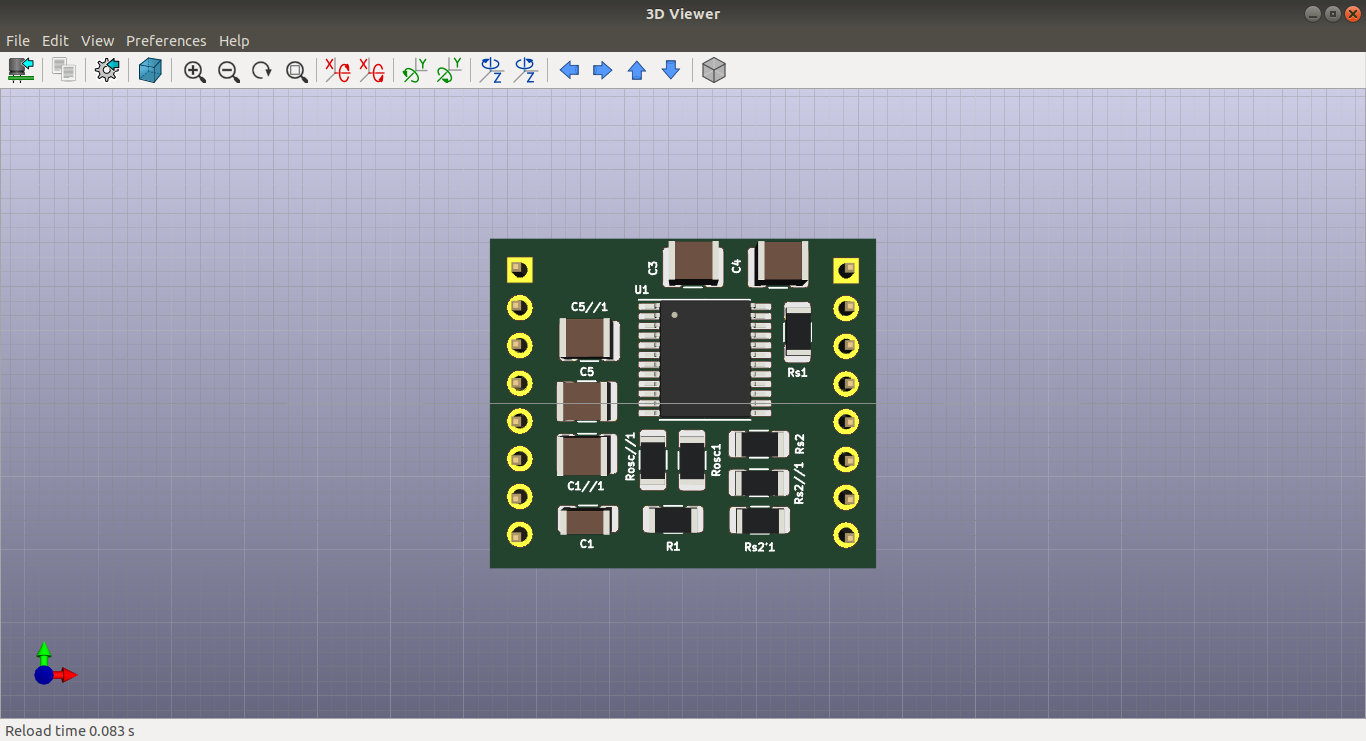
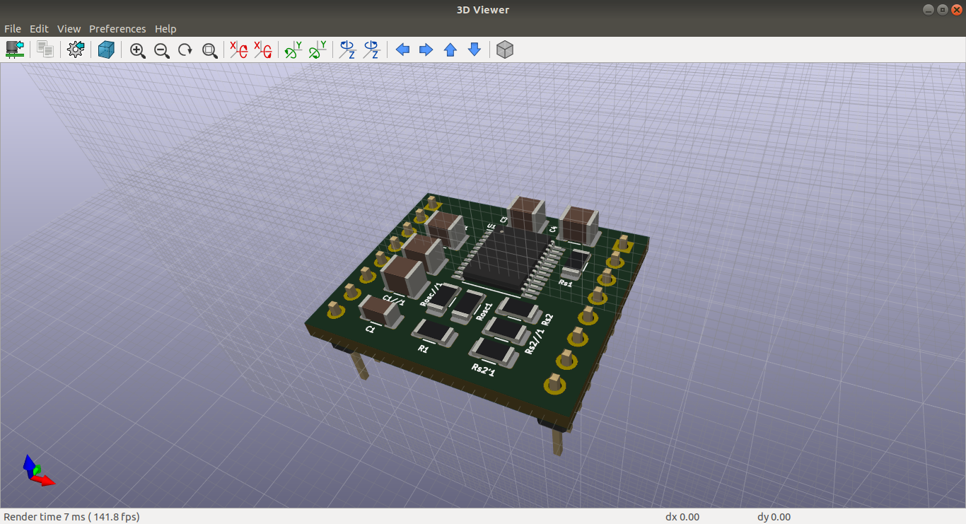
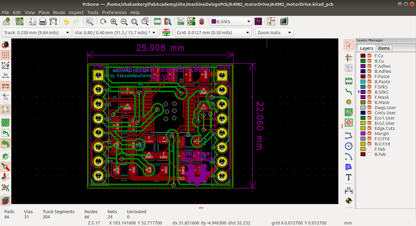
Silkscreen and Dimensions:
Files:
C) Programming Part
The programming part is divided in two main components
Plotting Software:
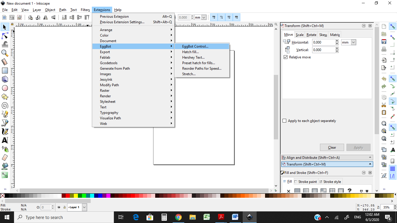
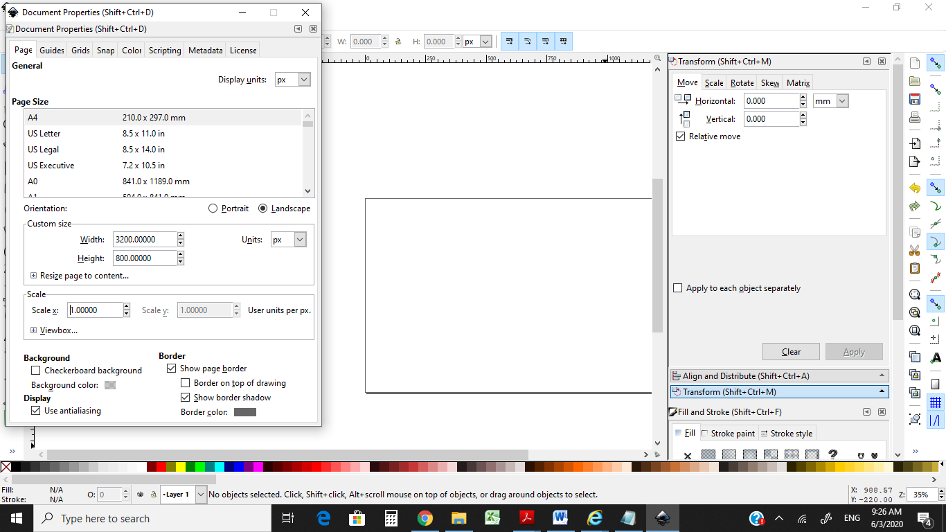
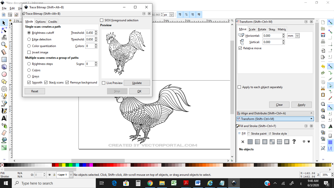
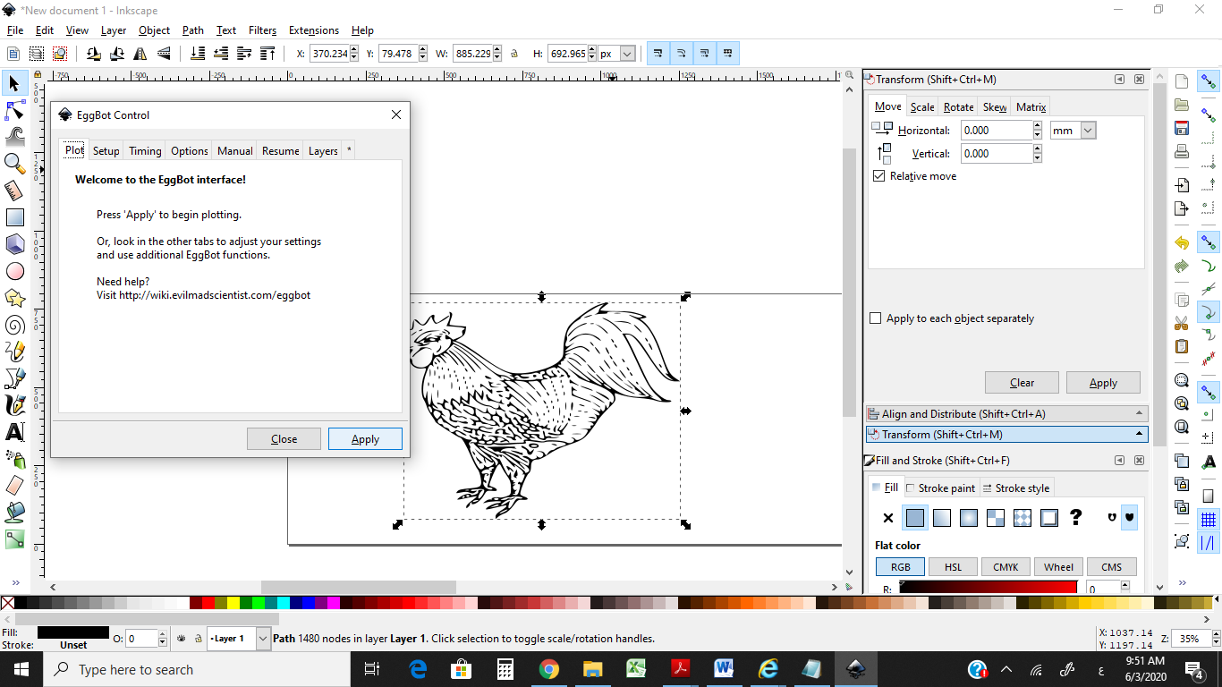
we will use Eggbot extensions with inkscape
-
Download and install from Inkscape
version 0.92.4
Install Inkscape in the default location, the main Program Files folder. - Download and run the EggBot installer
Steps: