Design Rules For PCB
Overview
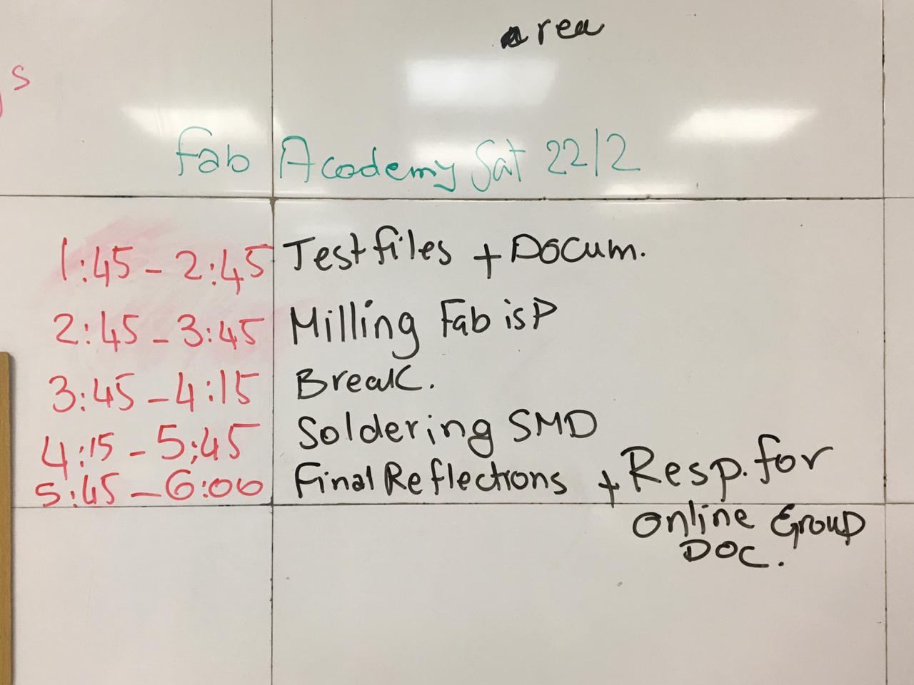
For this week we have to Characterize the design rules for your PCB production process: document feeds, speeds, plunge rate, depth of cut (traces and outline) and tooling.
In New Cairo lab we have two milling machines which are (MDX-40A & SRM-20). We tested both machines and got the best results from the SRM-20.
Know your Machine
MDX-40A
SRM 20
Machine
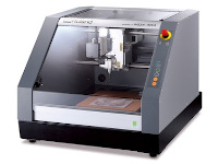
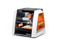
Work Area
12" x 12" x 4.13"
8" x 6" x 2.38"
Table Size
12" x 12"
9.14" x 6.17"
Max. Tool Size
1/4" or 6mm
1/4" or 6mm
Spindle Speed
4500-15000 rpm
3000-7000 rpm
Operating Speed
1.97 in/sec or 50mm/sec
1.18 in/sec or 30mm/sec
Power
110V / 2.1A
110V / 2.5A
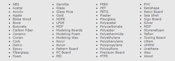
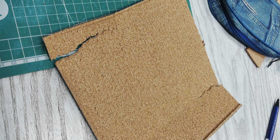
Materials
References
The Process
A) Fab Modules
A CAM program that will help us translate our design from Picture To G-code to Work with.
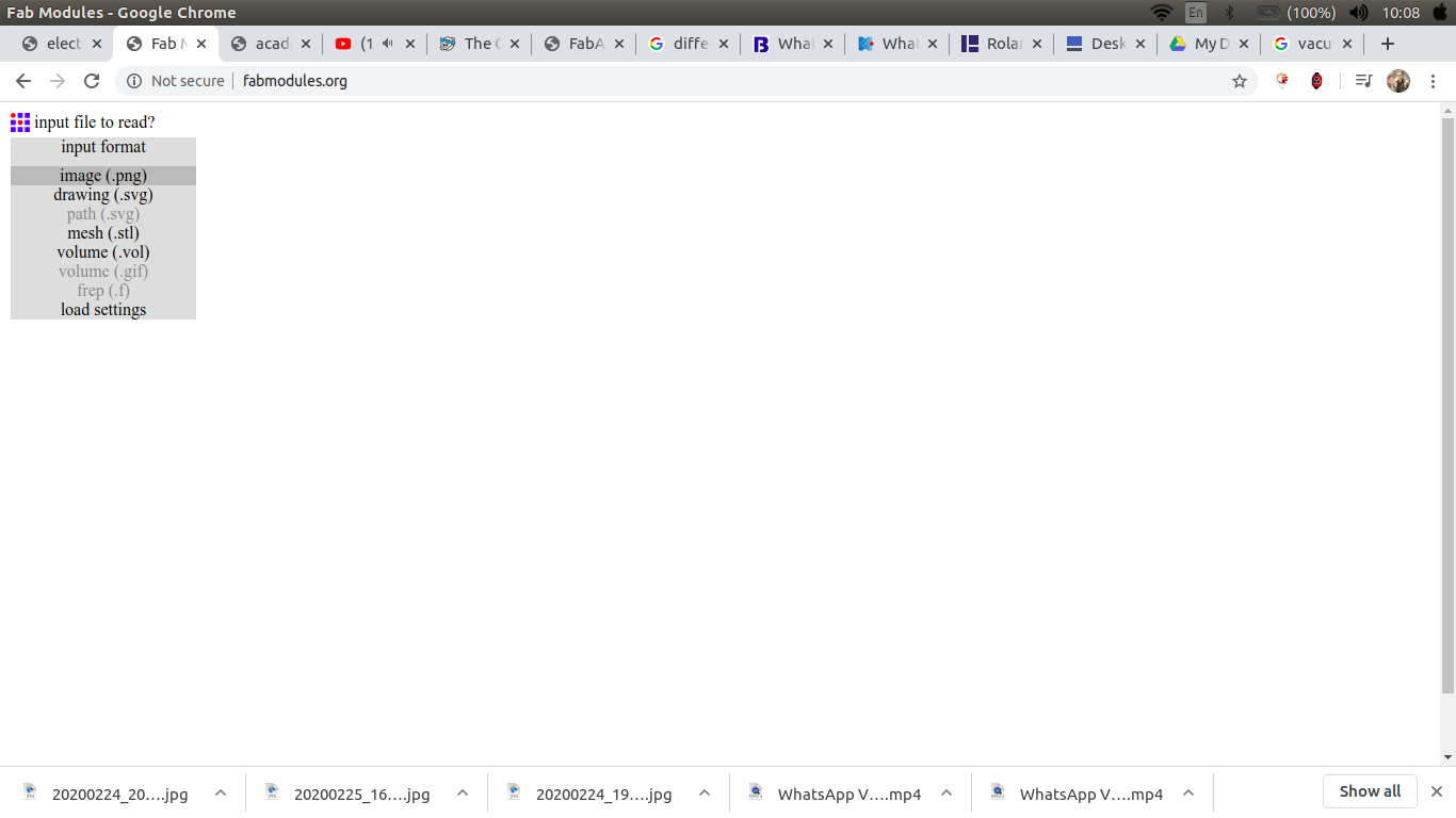
open fabmodules then choose the input to be an image.png.
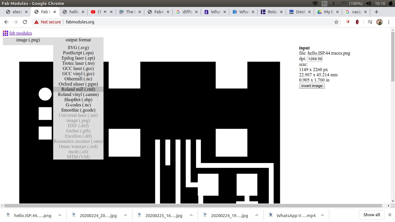
choose the output to be RML.
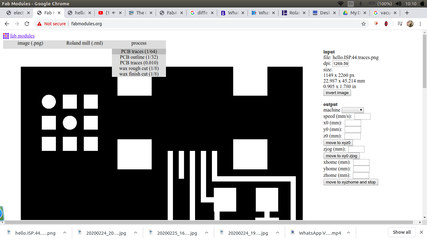
For the process choose either traces or outline.
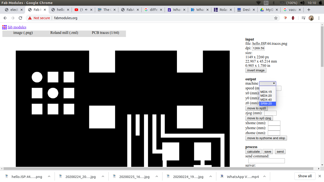
choose the machine, zero XYZ, choose no.of offset and the cut depth.
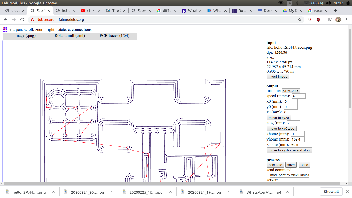
calculate then save.
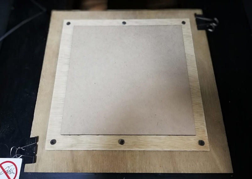
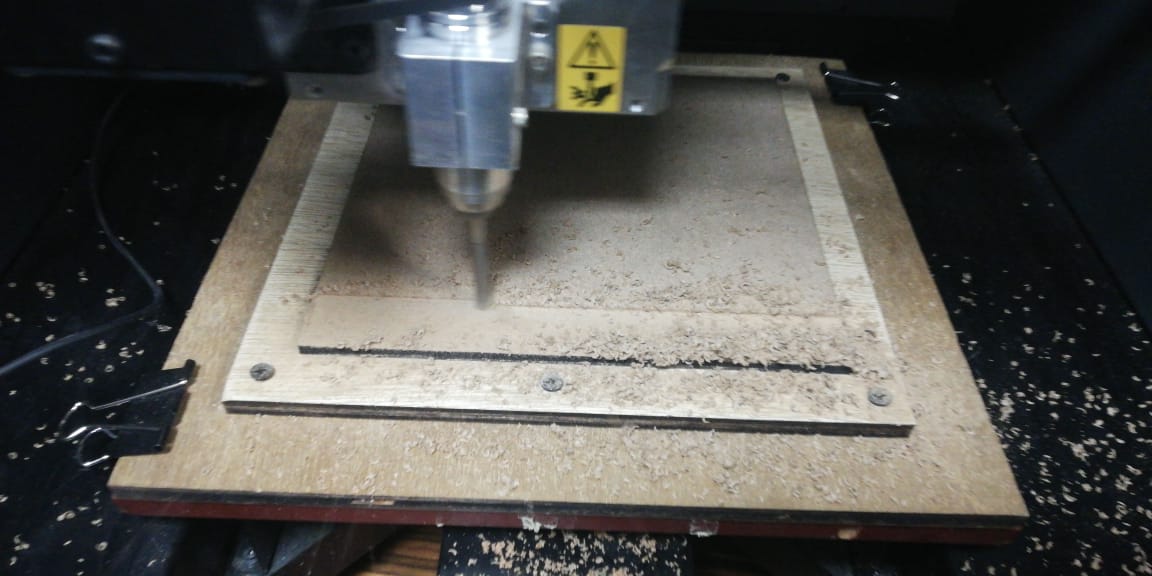
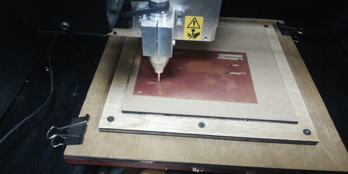
B) Roland MDX-40A
For the machining Roland MDX-40A was our first machine to use for that test.
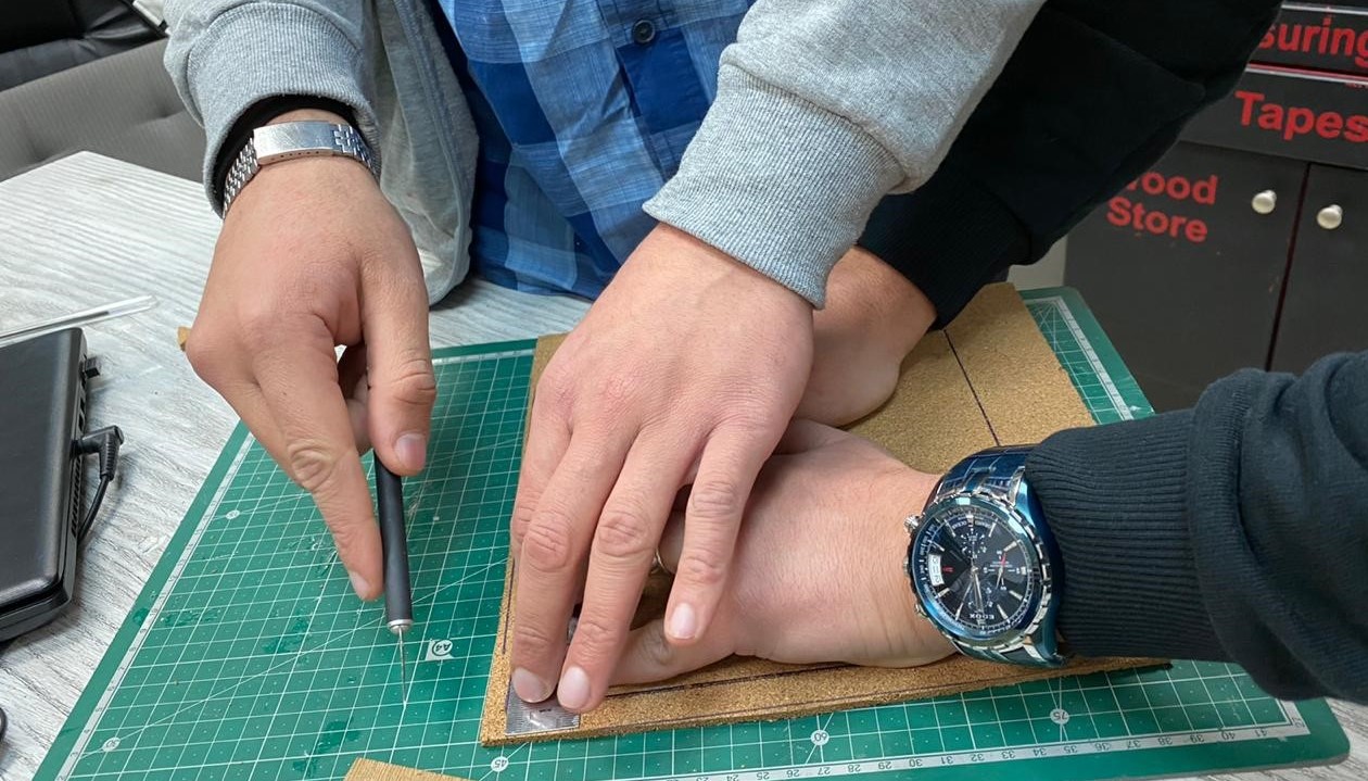
After fixing the sacrificial layer to the machine, fixing the FR 01 to it by double tape with the exact same processand precautions, We tried the test a couple of times but results didn't get any better.
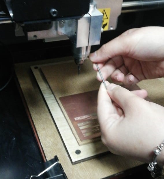
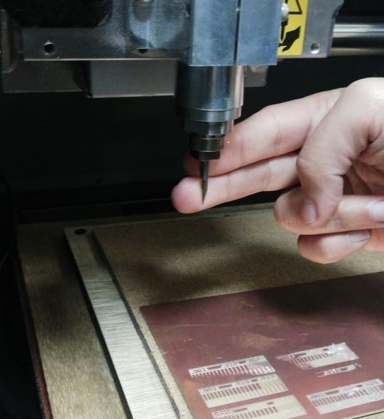
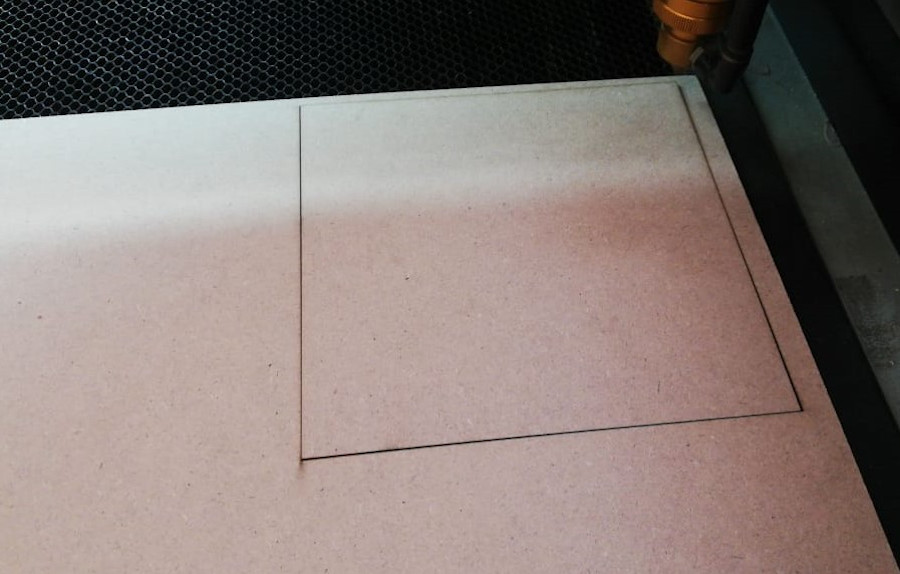
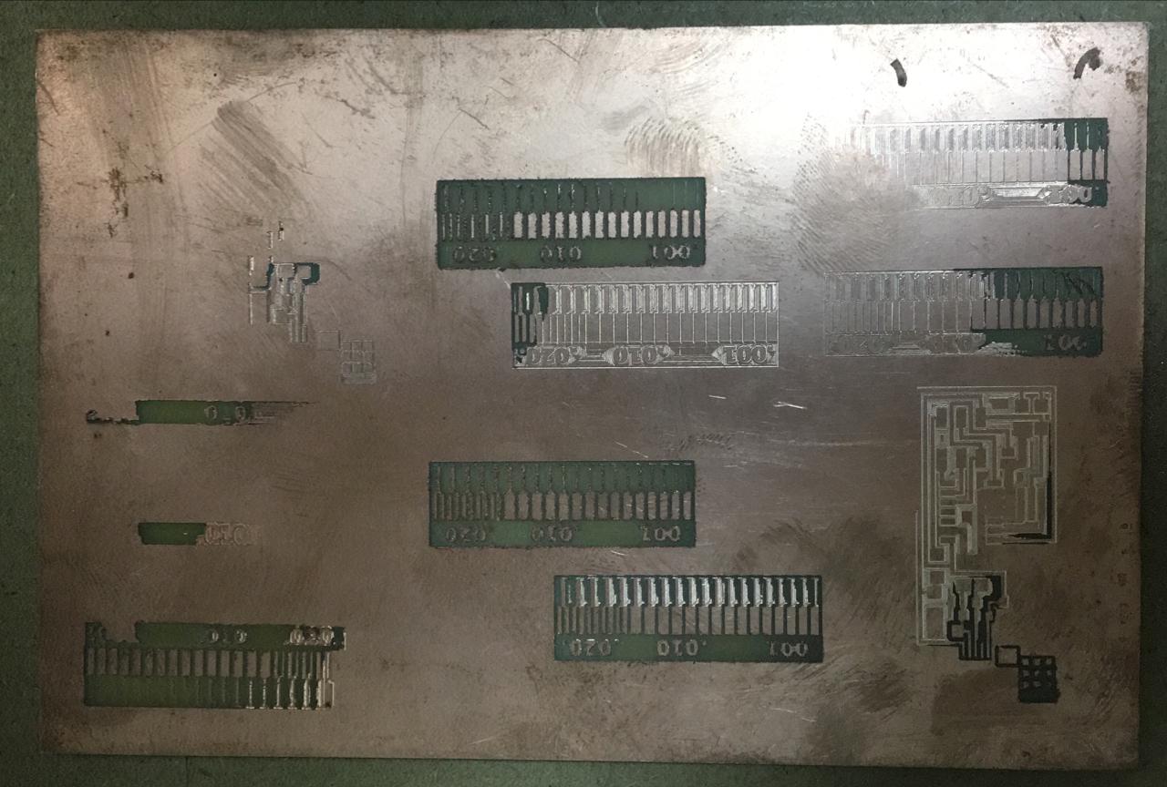
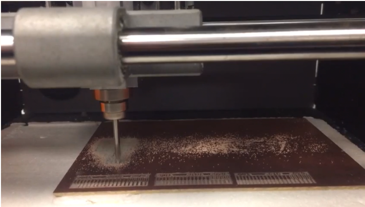
C) Roland SRM-20
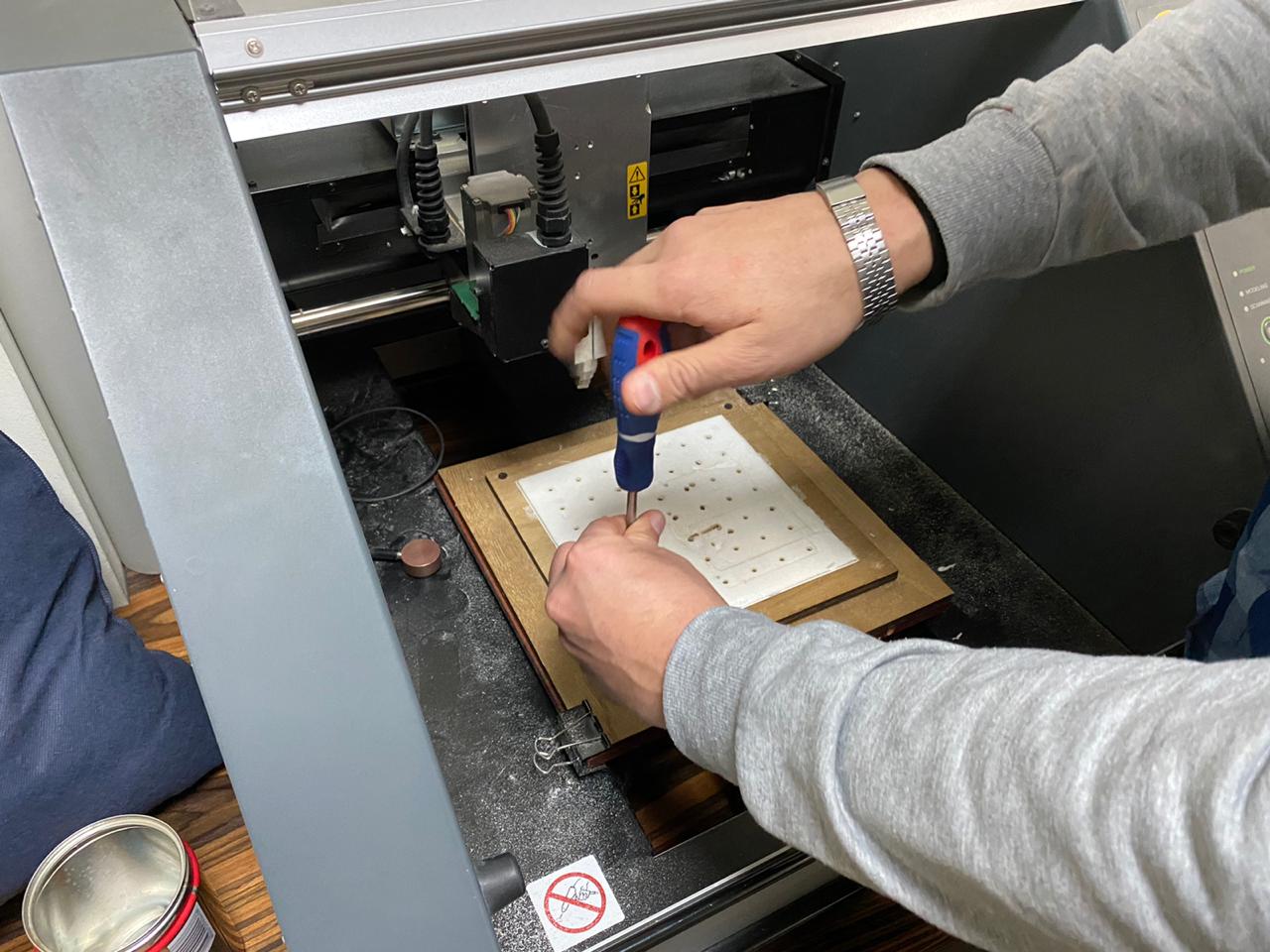
Having had hard time with the MDX-40A, we decided to switch to the SRM-20.
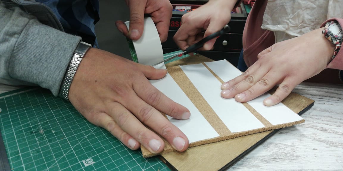
We went through the same initial steps preparing the machine, the work bed, fixing the FR01 with double tape and setting the zeros.
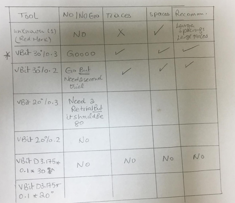
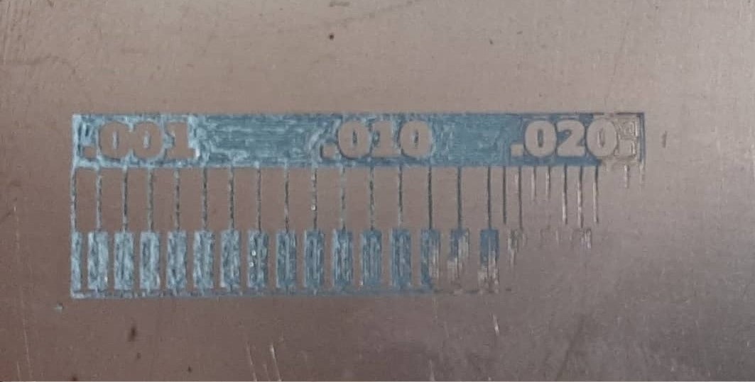
The best test resutls
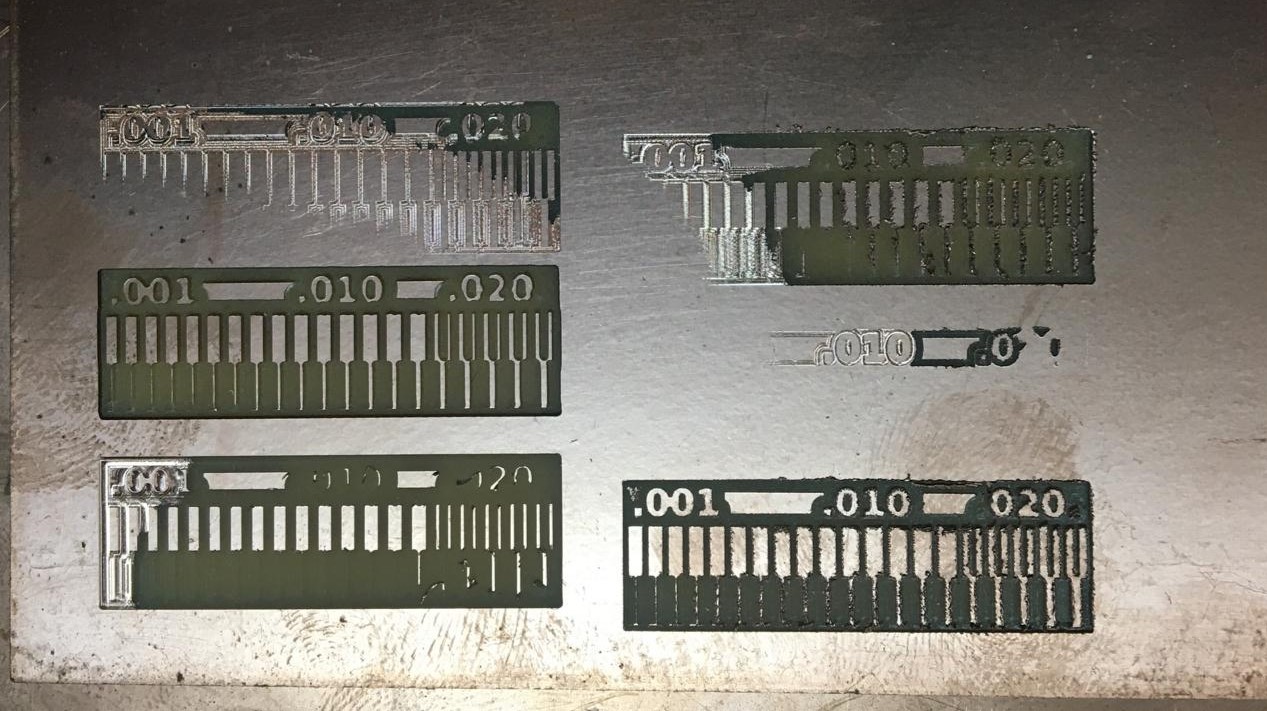
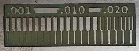
Conclusion:
1- High quality results was from SRM-20. 2- For milling, the best end mills are: [1/64", V bit 30/0.3 and V bit 30/0.2]. 3- For cutting, we tested the 0.1, it worked fine but we needed to adjust the borders.