Embedded Programming (WEEK 8 )
‣ Read a microcontroller data sheet
‣ Program your board to do something, with as many different programming languages and programming environments as possible
Introduction
An embedded system consists of both hardware parts and software parts designed to do a specific function or some functions. This week's activities are all about programming an embedded system. I am going to programme an PCB designed in week 5 electronic design. Below I have mentioned different terms/concepts related to embedded systems.
Microcontroller and Microprocessor
A microcontroller is a compact integrated circuit designed to govern a specific operation in an embedded system. A typical microcontroller includes a processor, memory and input/output (I/O) peripherals on a single chip.
Microprocessor is an IC which has only the CPU inside them i.e. only the processing powers such as Intel's Pentium 1,2,3,4, core 2 duo, i3, i5 etc [internet sources]
Family of Microcontollers
We can see many types of microcontrollers in the market based on manufacturing companies, architecture used, memories etc.
‣ Microcontroller 8051
8051 families are most commonly used microcontrollers.
Features• 8051 microcontroller is a 40 pin 8 bit microcontroller invented by Intel in 1981.
• 8051 comes with 128 bytes of RAM and 4KB of built in ROM.
• Based on priorities, 64 KB external memory can be incorporated with the microcontroller.
• A crystalline oscillator is embedded on this microcontroller which comes with a frequency of12 MHz.
• Two 16 bit timers are integrated in this microcontroller that can be used as a timer as well as a counter.
• 8051 consists of 5 interrupts including External interrupt 0, external interrupt 1,Timer interrupt 0, timer interrupt 1 and Serial port interrupt. It also consists of four 8 bits programmable ports. [internet sources]
‣ PIC Microcontroller
Micro-chip technology invented the Peripheral Interface Controller (PIC) which is very common among most of the professionals and experts.
Features• PIC microcontroller supports Harvard architecture.
• It consists of ROM, CPU, serial communication, timers and counters, oscillators, interrupts, I/O ports and a set of registers that also behave as RAM.
• Special purpose registers are also incorporated on chip hardware.
• Low power consumption makes this controller an ideal choice for an industrial purpose.
• Every PIC brings into play "stack" that is capable of saving return addresses.
• In the older version of PIC microcontrollers, stack could not be accessed by programming, but later versions can be easily accessed by programming.
• Low specification computer is enough to run the software that is capable of programming the PIC microcontroller circuit.
• Serial port or USB port is used to connect the computer with the microcontroller. [internet sources]
‣ AVR Microcontroller
AVR is referred to as Advanced Virtual RISC which was produced by Atmel in 1966.
• AVR architecture was produced by Vegard Wollan and Alf-Egil Bogen.
• The AT90S8515 was the first controller that was based on AVR architecture.
• However, AT90S1200 was the first AVR microcontroller that was commercially available in 1997.
• The flash, EEPROM and SRAM all are integrated on a single chip, which removes the possibility of joining any external memory with the controller.
• AVR has a watchdog timer and many power saving sleep modes that make this controller reliable and user-friendly. [internet sources]
Computer Architectures
In computer science, computer architecture is a set of rules and methods that describe the functionality, organization, and implementation of computer systems.Some common computer Architectures seen in microcontrollers are
‣ Harvard architecture
The Harvard architecture is a computer architecture with separate storage and signal pathways for instructions and data. It contrasts with the Von Neumann architecture, where program instructions and data share the same memory and pathways.
‣ CISC
Stands for "Complex Instruction Set Computing." This is a type of microprocessor design. The CISC architecture contains a large set of computer instructions that range from very simple to very complex and specialized
Memories
There are normally 3 types of memory present in microcontrollers. These are SRAM, FLASH, and EEPROM memories.
‣ SRAM- its memory where programme is written and read repeatedly
‣ FLASH- Data stored in flash memory is permanent similarly to BIOS in our computer
‣ EEPROM- Data stored in EEPROM will remain unchanged even when power is gone off
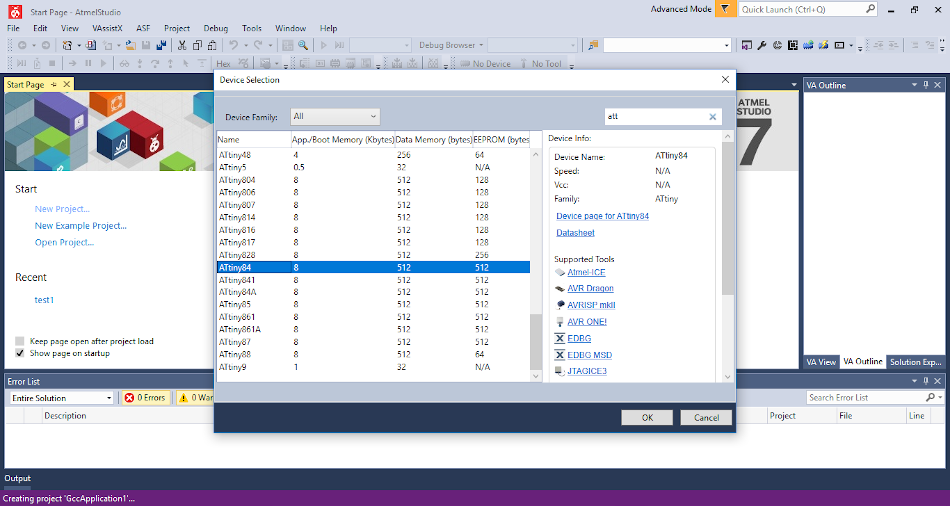
About ATtiny 44 Microcontroller
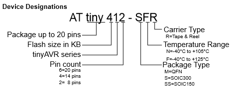
The high-performance, low-power Microchip AVR RISC-based CMOS 8-bit microcontroller combines 4KB ISP flash memory, 256-Byte EEPROM, 256B SRAM, 12 general purpose I/O lines, 32 general purpose working registers, an 8-bit timer/counter with two PWM channels, a 16-bit timer/counter with two PWM channels, internal and external interrupts, an 8-channel 10-bit A/D converter, a programmable gain stage (1x, 20x) for 12 differential ADC channel pairs, programmable watchdog timer with internal oscillator, a internal calibrated oscillator, and three software selectable power saving modes. By executing powerful instructions in a single clock cycle, the device achieves throughputs approaching 1 MIPS per MHz, balancing power consumption and processing speed. Please see the DATA SHEET for more details.
PIN CONFIGURATION:-
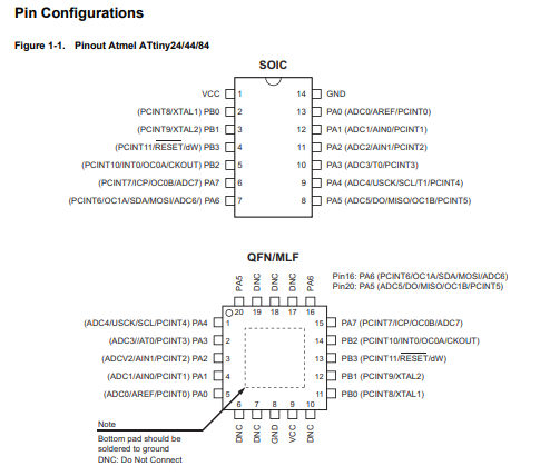
VCC : Supply voltage
GND : Ground
Port B (PB3...PB0) : Port B is a 4-bit bi-directional I/O port with internal pull-up resistors (selected for each bit). Don't need to add a pull-up resistor externally for button's and other purposes.
RESET : Reset input. A low level on this pin for longer than the minimum pulse length will generate a reset, even if the clock is not running. a reset will just reset the programm that currently runnig .
Port A (PA7...PA0) : Port A is a 8-bit bi-directional I/O port with internal pull-up resistors (selected for each bit). As inputs, Port A pins that are externally pulled low will source current if the pull-up resistors are activated.
SCK(Serial Clock) : Programming clock, generated by the In-System Programmer (Master).
MOSI (Master Out - Slave In) : Communication line from In-System Programmer (Master) to target AVR being programmed (Slave).
MISO (Master In - Slave Out) : Communication line from target AVR (Slave) to In- System Programmer (Master).
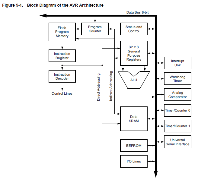
BLOCK DIAGRAM :-

ARCHITECTURE :-
Arduino IDE for Programming Microcontrollers
Arduino Integrated Development Environment is a cross platform application used for coding and uploading programmes to arduino boards as well as other third party microcontrollers available in market.
Here I used arduino IDE for coding and uploading my programme to Attiny 44. For doing this we need to do following preprocessing for successful uploading .
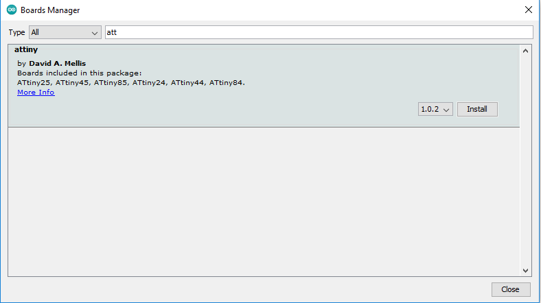
Firstly we need to add our microcontrollers Attiny to arduino board managers. For this I referred a tutorial
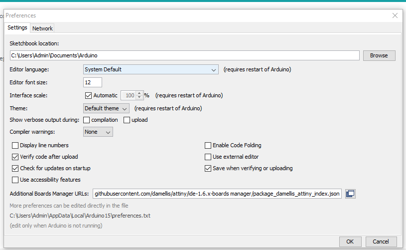
https://raw.githubusercontent.com/damellis/attiny/ide-1.6.x-boards-manager/package_damellis_attiny_index.json
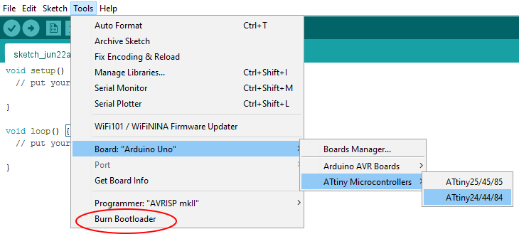
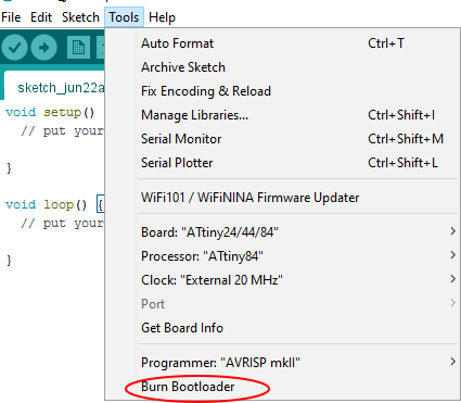
Firstly we need to do Bootloader operation. For that connect the board using a 6 pin ISP. Now open 'Tools" and
select the required board. Processors, clock.. and click “ Burn Bootloader “
Now you can program the board for infinite times
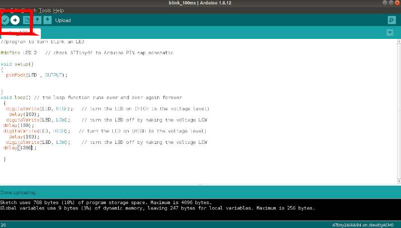
I programmed my board to blink the led with a delay. I used the program below programme to do the task.
      //program to turn blink an LED

      #define LED 2   // check ATTiny44 to Arduino PIN map schematic

      void setup()
      {
        pinMode(LED , OUTPUT);


      }
      void loop() // the loop function runs over and over again forever
       {
        digitalWrite(LED, HIGH);   // turn the LED on (HIGH is the voltage level)
         delay(100);
        digitalWrite(LED, LOW);    // turn the LED off by making the voltage LOW
       delay(100);
       digitalWrite(LED, HIGH);   // turn the LED on (HIGH is the voltage level)
         delay(100);
        digitalWrite(LED, LOW);    // turn the LED off by making the voltage LOW
       delay(1000);

       }
‣ Successfuly tested(Video)
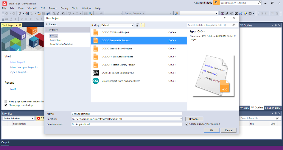
‣ Atmel Studio 7
Atmel Studio 7 is the integrated development platform (IDP) for writing, building and debugging programmes/applications written in C/C++ or assembly code for AVR and SAM microcontrollers.
After Arduino IDE, I used Atmel studio to programme my Echo Board. The steps I followed are mentioned below.
↠ Download and install Atmel studio 7 windows Link
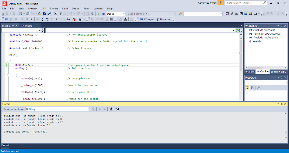
Now you can write the code. I wrote a program for blink the Echo board led an application that I did in Arduino IDE.
↠ I referred to this Tutorial.
‣ My Code in assembly language
#include// AVR input/output library #define F_CPU 20000000 // Since we connected a 20MHz crystal into the circuit #include // Delay library main() { DDRA=(1<<2); //set pins 2 in the A port as output pins. while(1) // infinite loop { PORTA|=(1<<2); //Turns pin7 ON. _delay_ms(1000); //wait for one second. PORTA&=(!(1<<2)); //Turns pin7 OFF. _delay_ms(1000); //wait for one second. } }
‣ Working Video
Compare the performance and development workflows for different microcontroller families
Link to our group assignment page