This week we had 2 assignments one was the group assignment and the other was the individual assignment.
The individual assignment was to redraw an echo hello-world board,and to add a button and LEd.And then to check the design rules,make it and test it.
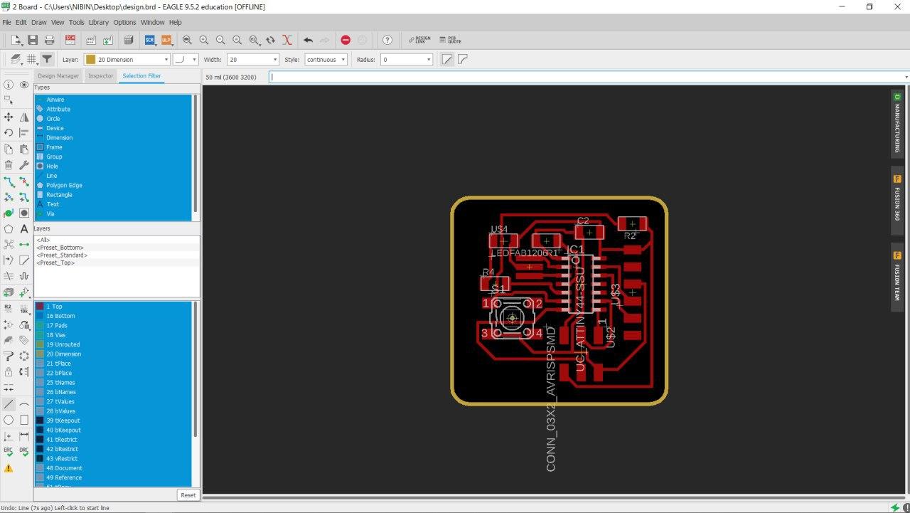
First of all we started with designing the pcb. For this we used the Autodesk Eagle software.
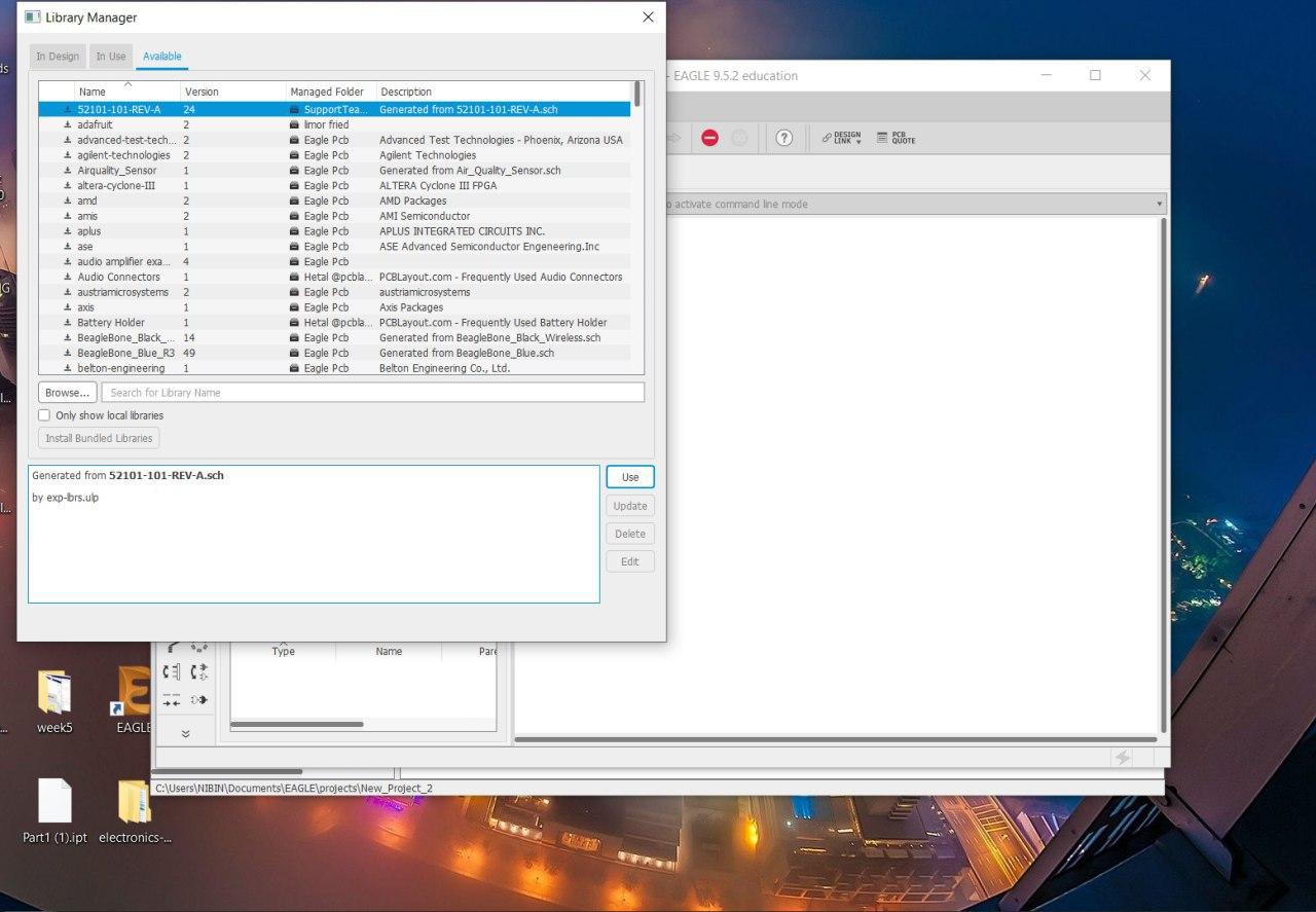
For the components we downloaded a component library from the fablab directory.
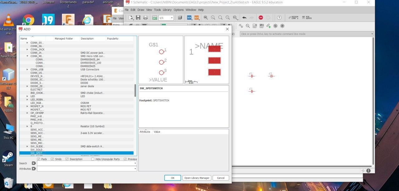
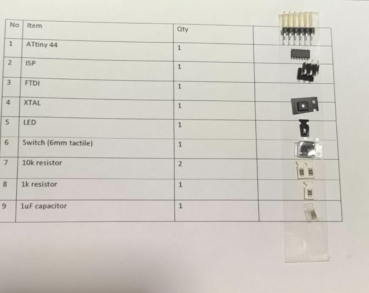
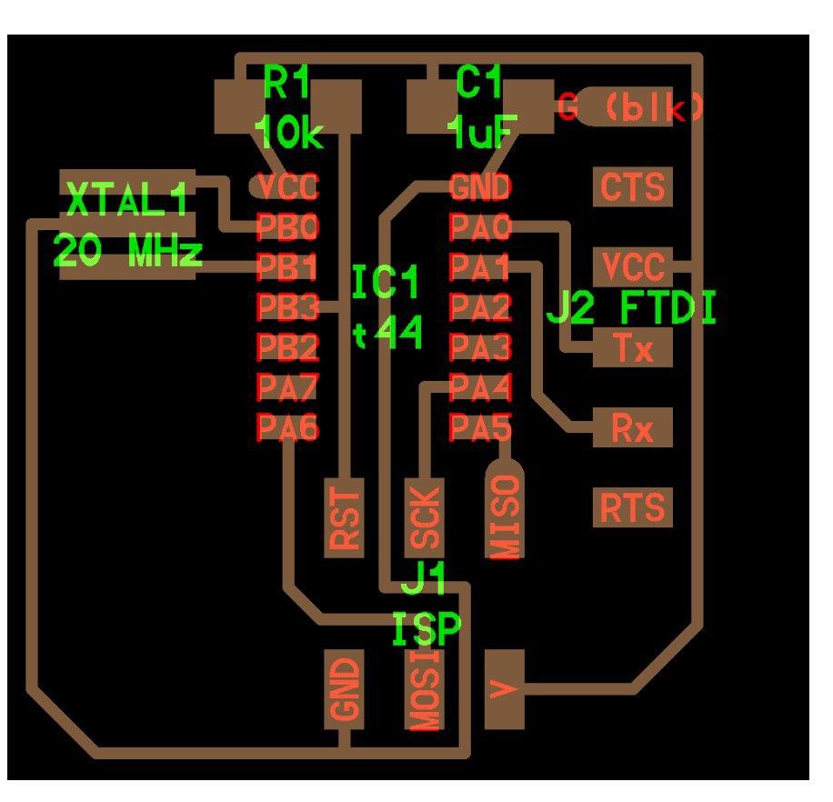
The components we needed to us are as follows.
The next thing to do is connect the components.
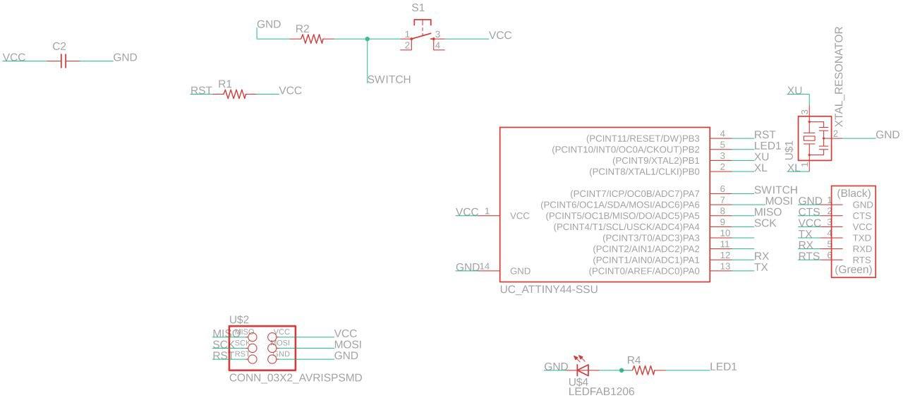
The pcb design refered was the hello echo world board.
After connecting the components i selected the auto route option.And after severel number of rearrangments i got 100 percentage.
After this i did export the schematic diagram,while doing this we have to make sure that the layers should be hidden and only the top layer should be visible ,then i did export the diagram as a png file with 1000 resolution and the settings changed to monochrome.
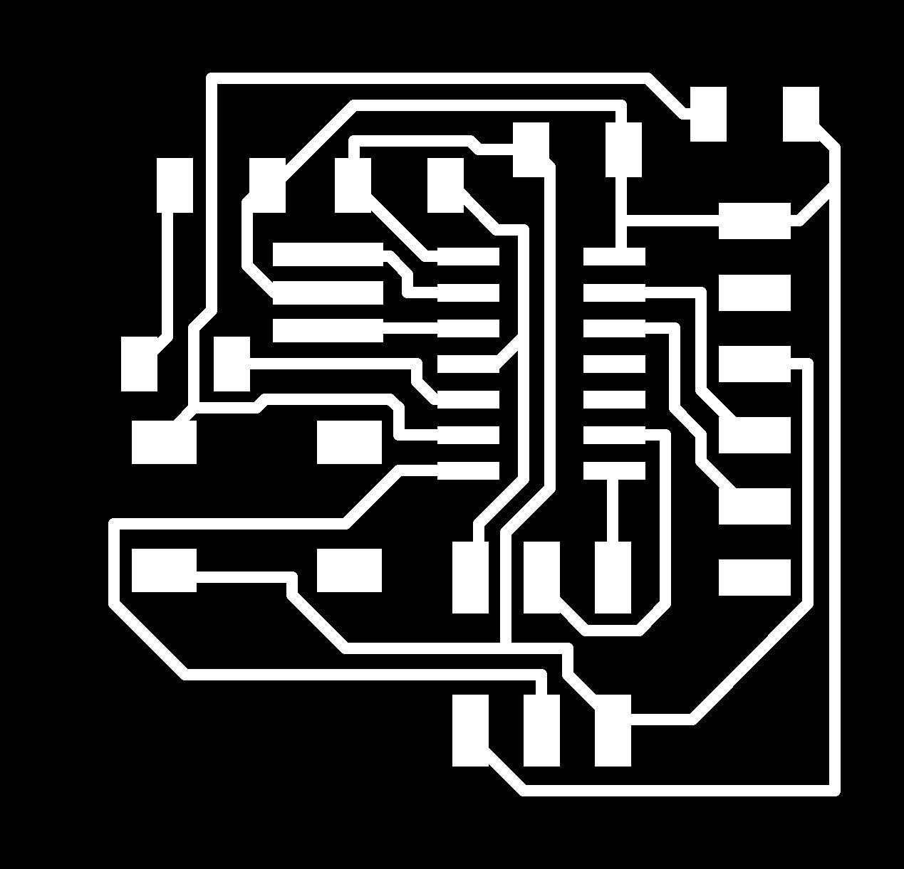

The border and the diagram was exported as two different files.
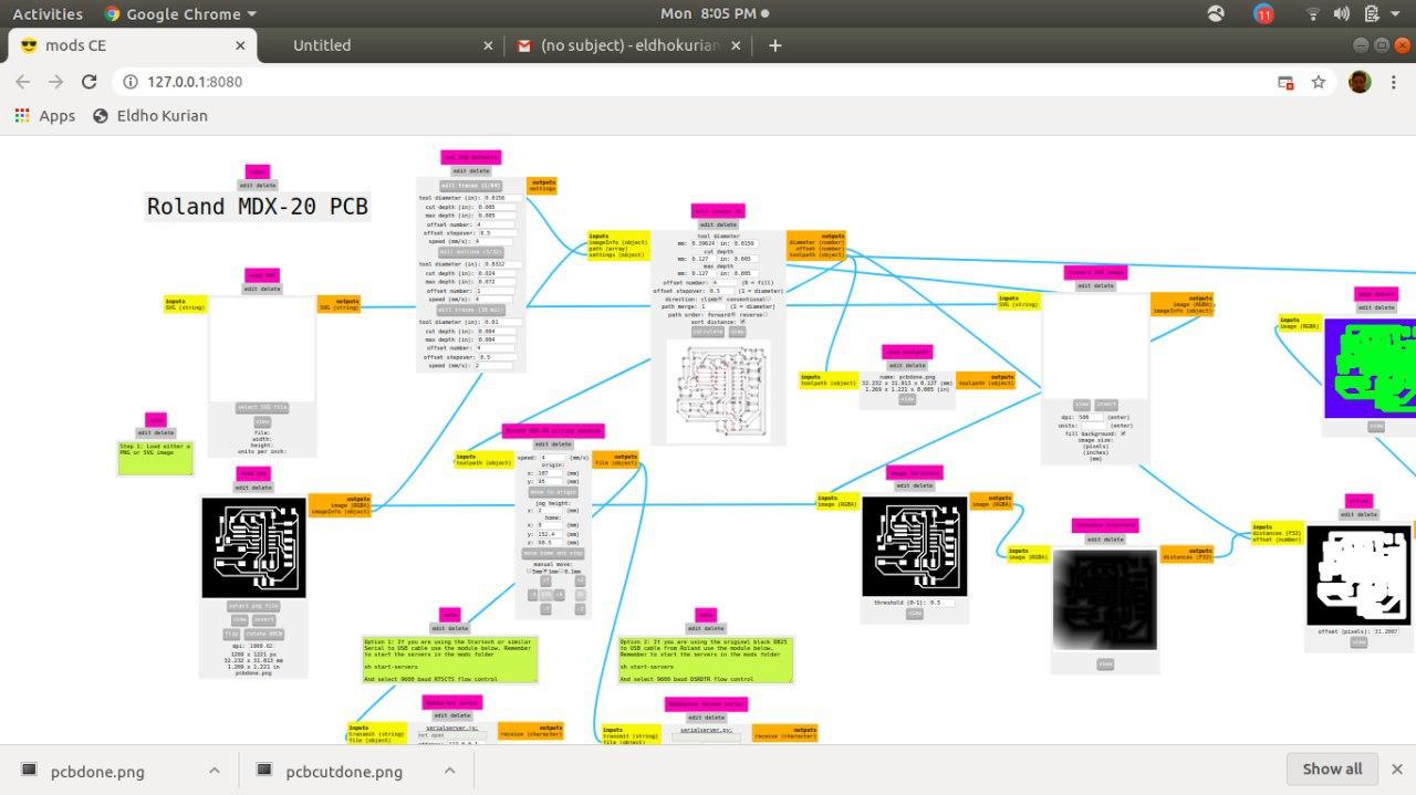
After this is the milling process,the machine we used was Roland mdx 20.
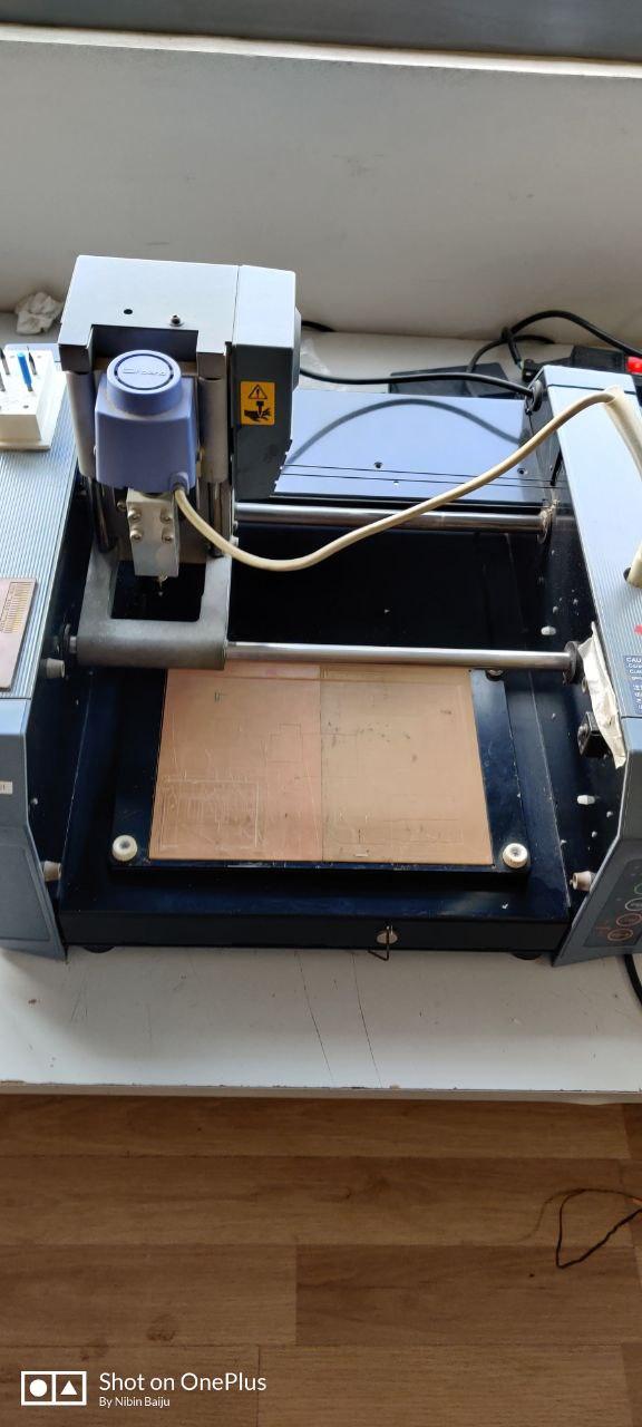
With the use of the mod software we set the parameters for pcb milling.

After milling was to solder the components to my board.
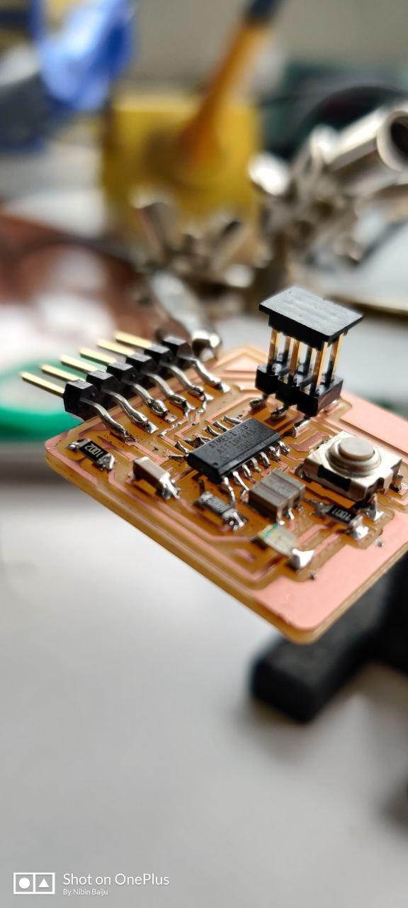
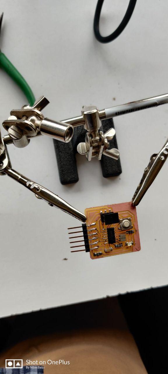
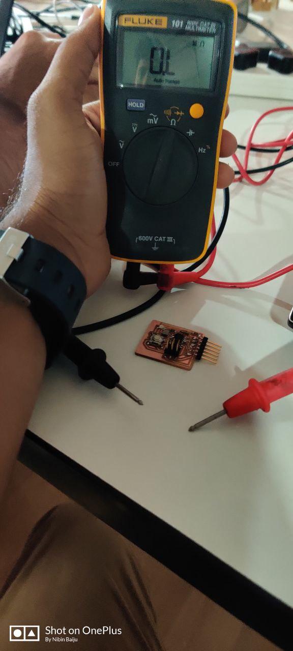
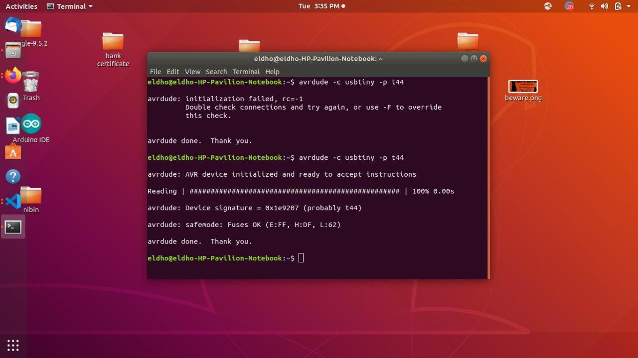
Then we need to test the continuity and it was successful.
But first my ic was not recognized then i had to resolder my micropresessor and it was successful
Then i installed the arduino software for programming my ic.
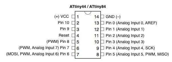
With the help of ardino pin map i did the programming in arduino.
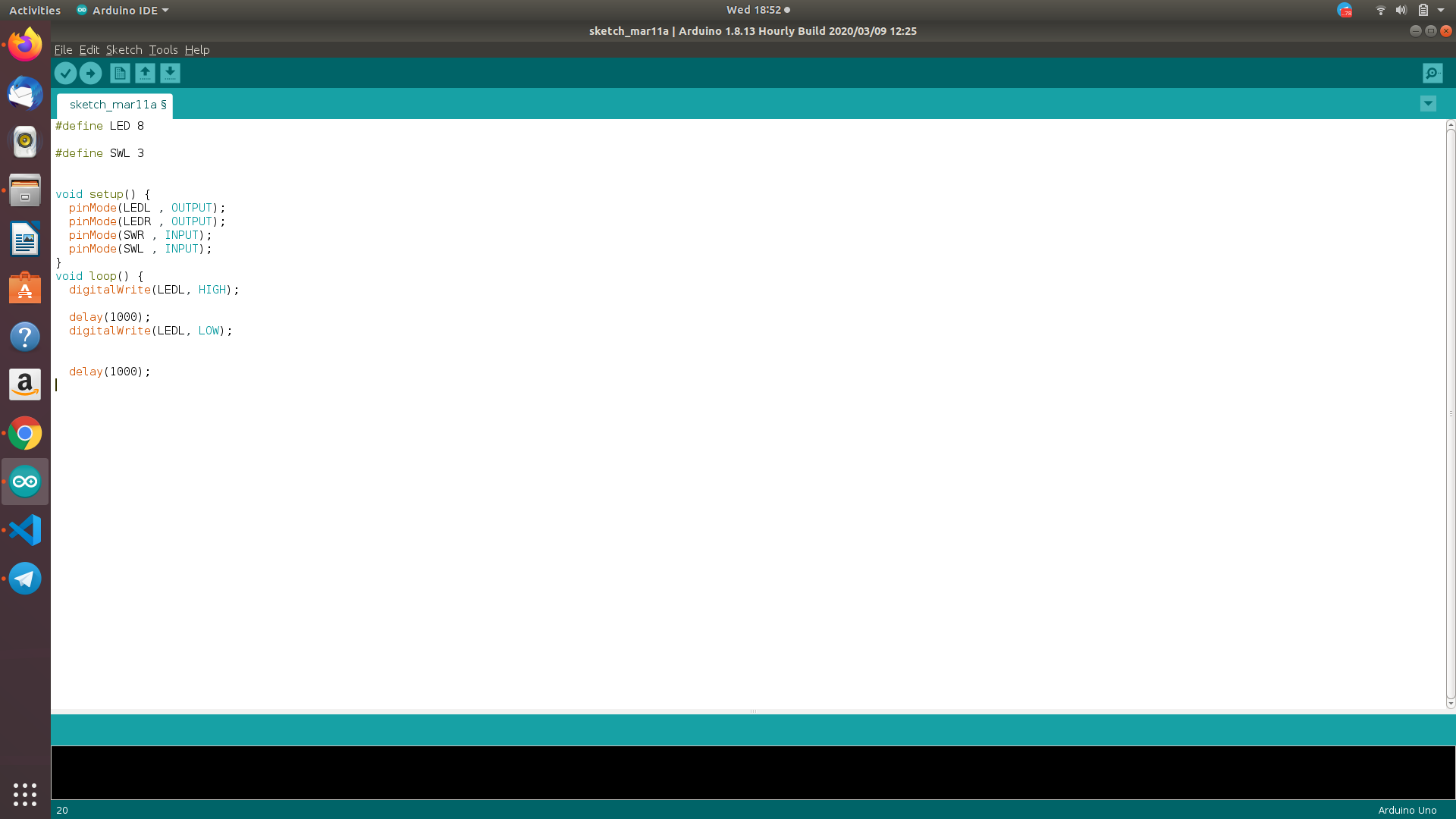
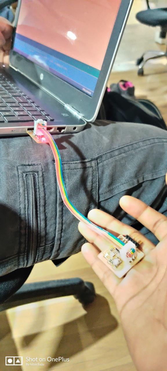
Well after progrmming in arduino i got my ic's LED blink in an interval of 1 second.