input devices (week09)
Group Assignment
- Probe an input device(s)'s analog and digital signals
Check potentiometer values by serial monitor
I've measured the value from potentiometer over serial interface. Because of restriction to access to lab, I made ATtiny3216 breakout board for experiment. Also, I tried the same on Arduino UNO for confirming the program behavior using sound synthesis library.
This week, I wrote the outcome in individual web site.
Prove a potentiometer's analog and digital signals - 4 June 2020
2 months after from staying at home time under COVID-19 situation, I come back to lab and did an experiment using oscilloscope.
Correction of pulse wave in oscilloscope screen
Before using oscilloscope, I corrected the presented wave in oscilloscope screen.
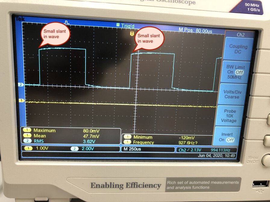
There are small slants for each wave in oscilloscope.
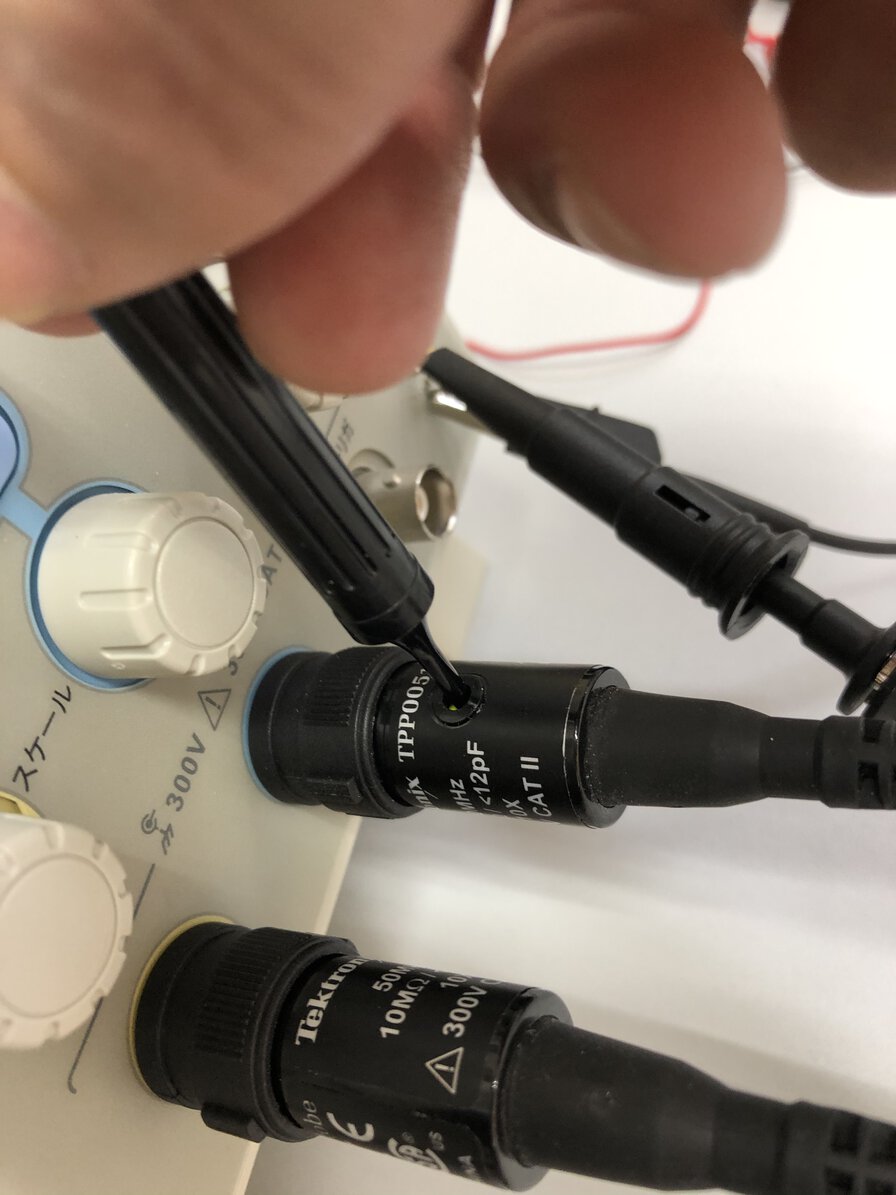
Using a attachment tool of oscilloscope, turn screw and correct the position of wave.
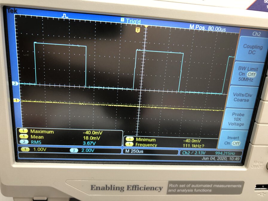
The shape of pulse wave looks to be right angle.
Connection
Using input board that I made in week 9 (Input devices with ATTiny3216 breakout board), I read value of analog and digital value that are controlled by a potentiometer.
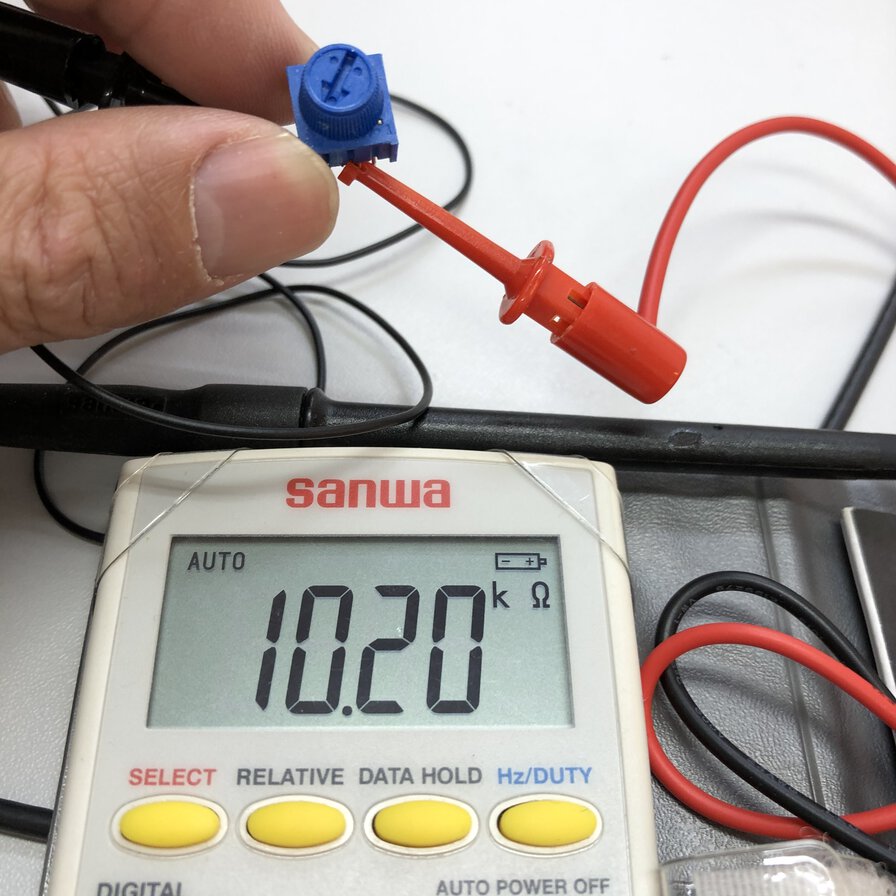
Resister value of potentiometer is around 10kΩ.
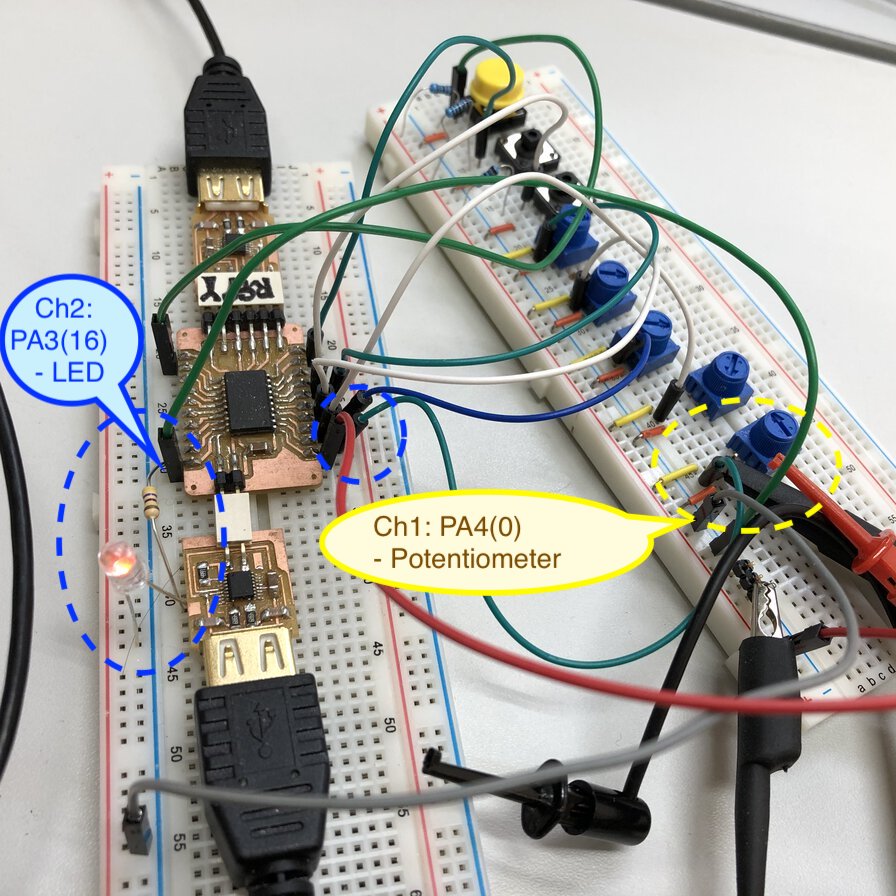
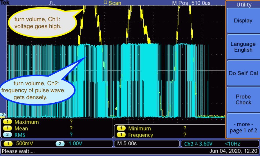
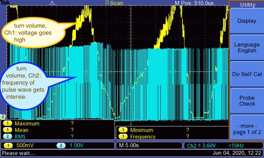
Using 2 channels of oscilloscope, I probe voltage values at the point of input device(potentiometer) by Ch1 and pulse wave in output device(LED) by Ch2.
Source code
Following is an extract of source code of "testAnalogInput_LED.ino" (Board: ATtiny3216)
  const int PA4 = 0;
  const int PA3 = 16;
  int p1 = 0;

  void setup() {
    Serial.begin(115200);
    pinMode(PA4, INPUT);

    pinMode(PA3, OUTPUT);
  }

  void loop() {
    p1 = analogRead(PA4);
    Serial.println("p1:PA4: ");
    Serial.println(p1);

    int intensity = map(p1, 0, 1024, 0, 255);
    analogWrite(PA3, intensity);
    delay(10);
  }
testAnalogInput_LED.ino
Experiment result
When viewing "pulse" analogWrite() with intensity