Output Devices
Week11
Wiring of devices with power source to my Arduino.
As my object of interest regarding the operation of output devices, I chose peristaltic pumps - which are nothing but a regular DC motor connected to a silicon hose by a set of rollers in circular pattern that press a tiny amount of water though the hose with every turn (Fig.01). Setting up this device forms part of my final project where I need these pumps to conduct water from a storage into the irrigation pots.
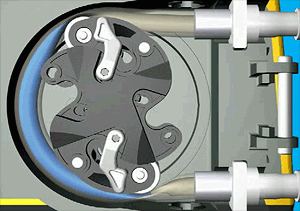
Fig.01: Mechanism of a perstaltic pump
The setup is pretty straightforward and picks up from my week 09 assignment on input devices: I use those very moisture sensors to trigger the pumps once the moinsture value has dropped beneath a certain threshold. For starters, this value is chosen rather arbitrarily; in operation, the moisture will rather be measured under monitoring aspects anyway. It will merely serve as a control regarding the question how water demand (as controlled entirely by the water level sensors inside the irrigation devices) corresponds with soil conditions.
On Amazon I found this model that met my expectations regarding the amount of water to be pumped: 200mL per minute seem reasonable to me. The pump was originally designed to be used in an aquarium, it runs in the tempoerature range of 0 to 40°C, may be run between 1 and 500rpm, and uses up to 80mA. This latter value indicates the maximum current required to run the device which occurs soecifically when the pump is being set into motion. Under normal operational conditions, the current will be much lower than that; nevertheless, the use of a relay or MOSFET to operate the pump was mandatory to protect the board from being fried. I chose a MOSFET from our FabLab's inventory: a UTC 200V, 9A N-Channel Power MOSFET, designed to operate devices at much higher voltages and currents than the 12V peristaltic pump - but works for me anyway. The MOSFET comes with 3 pins that are referred to as (G)ate, (S)ource and (D)rain. The order by which the pins are positioned on the MOSFET may vary between brands, hence a look into the data sheet is necessary to prevent the board from receiving too much current. Fig.02 shows two snippets from the data sheet, indicating the pin numbers and their corresponding labels. In my case, pin 1 on the left is the gate, pin 2 is drain, and pin 3 is source.
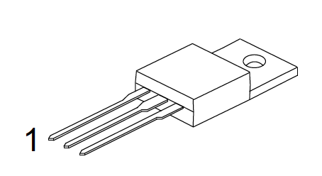
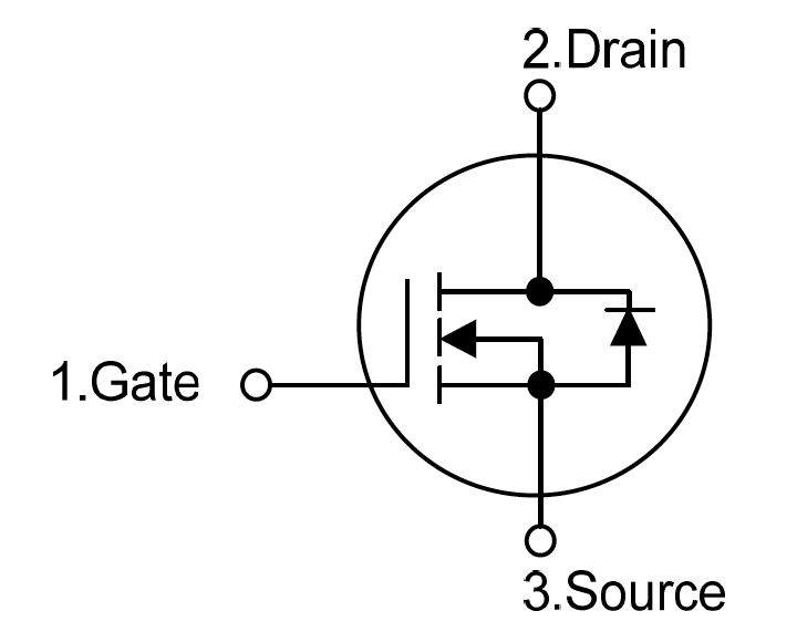
Fig.02: MOSFET sketch and pinout from data sheet.
The gate pin connects to PWM pin 9 to receive analog write signals from the Arduino. Drain connects to the VCC side of the circuit, receiving from the device, and Source connects double to ground: once towards the device, the other connects to GND on the Arduino. Between the jumper to the output pin and the jumper to GND on the Arduino, a 10kOhm resistor is added to prevent peaks of current hitting the board.
Due to the lockdown, I was not able to get a hold of a suitable power supply to run the peristaltic pump I bought for a previous demonstration project, hence I decided to simply run a 6V DC motor instead that would be triggered by critical values that the moisture sensor reads; Fig.03 shows both devices, including an impression with regard to the difference in size. For the wiring, I found decent instructions for the usage of high-power control with an N-Channel MOSFET at bildr.blog (Fig.04). This setup allowed me to make my first experiences with an ouput device that depends on an external power supply - in this case a 9V battery.
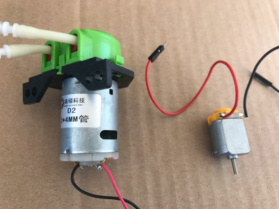
Fig.03: 12V peristaltic pump (left) and 6V DC motor.
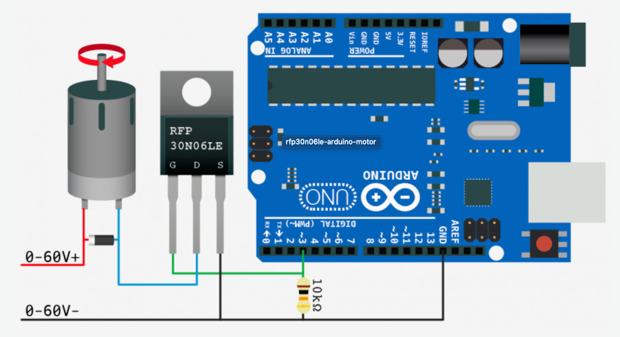
Fig.04: Wiring example of Arduino-run high power device.
I used the input setup from my week 09 assignment and added the MOSFET with the DC motor as described above. It actually worked on the first try this time - however, I had a lot of trouble half a year ago on the demo project. If there was one thing I learned from those early trials, it was to keep the circuit simple, omit everything that is not essential to the function. In my case that meant kicking out the capacitor recommended in Fig.04 and a diode I read about in a different tutorial with the purpose to control the flow of current in the circuit. Fig.05 shows the final setup for the MOSFET part, Fig.06 exhibits the full picture, including the moisture sensor and the power source with all the corresponding wiring.
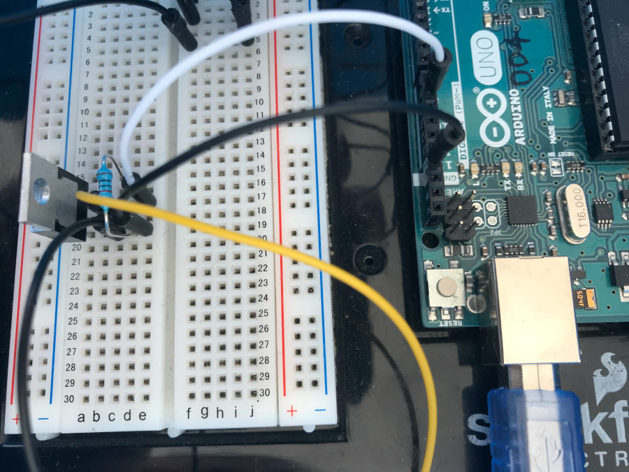
Fig.05: MOSFET wiring to Arduino.
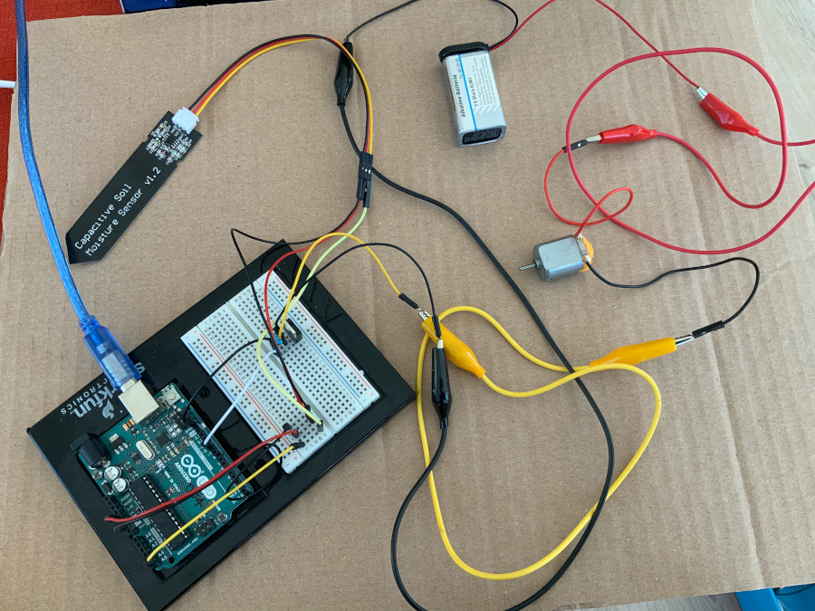
Fig.06: Full setup with Arduino, DC motor, moisture sensor, MOSFET and power source.
Coding and uploading the sketch to the Arduino.
This code is basically an extension to the sketch I coded in week09. The important new elements are the pinout lines for the DC motor I picked as output device: int DC = 9;pinMode(DC, OUTPUT);
and the while loop:while (MoistureValue [smaller than] CriticalLO){analogWrite(DC, 50);delay(1000);MoistureRead = analogRead(Sensor);MoistureValue = (798-MoistureRead)/3.75;Serial.println(MoistureValue);}
This loop compares the moisture level of the probe to a value that was pre-defined as critical level in one of my global variables: const int CriticalLO = 60;.
Before the loop function ends, the code indicates to switch off the DC motor in case the moisture level is above the critical value: analogWrite(DC, 0);delay(1000);
Originally, I wanted to start the engine gently with an smooth increase in rpm. After lots of unsuccessful trials for a proper placement of a code line like for (RPM=0,RPM[smaller than]255;RPM=RPM+5){analogWrite(DC, RPM); delay 50;} I dropped it for another day and focused on only running the motor on low RPM.
But even that turned out problematic and cost me some hours until I eventually found a code that surely is not the most elegant of its kind - but it works. And it is mine. See Fig. 07 for details and the entire sketch in my Downloadables below.
