Electronics Production
Week04
For my individual assignment I started off with a board template by Andy Bardagjy provided on the FabAcademy website. This template is documented as schematic (Fig.01) and assembly drawing (Fig.02), plus the board design (Fig.03) and contour desing (Fig.04) for export to milling.
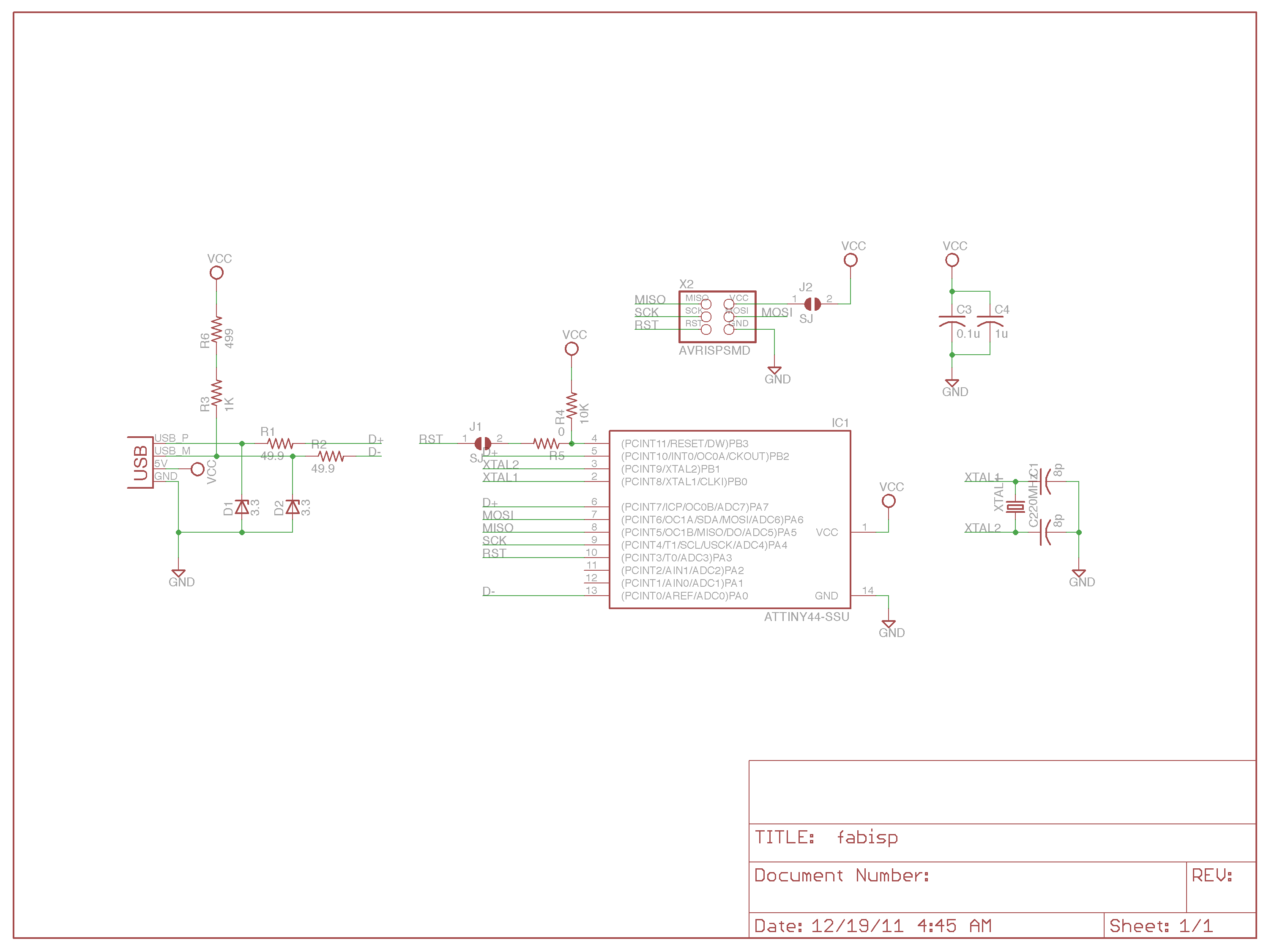 Fig.01: Schematic drawing. |
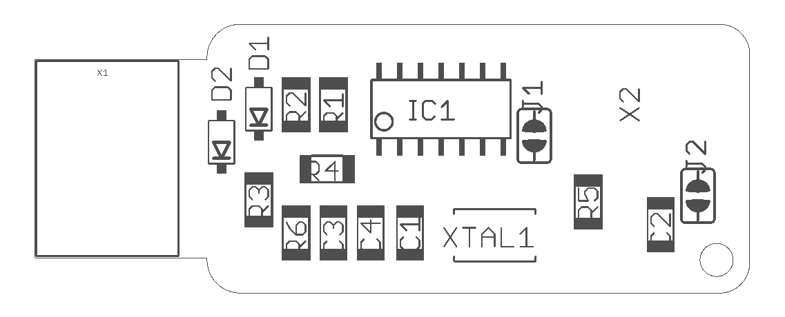 Fig.02: Assembly drawing. |
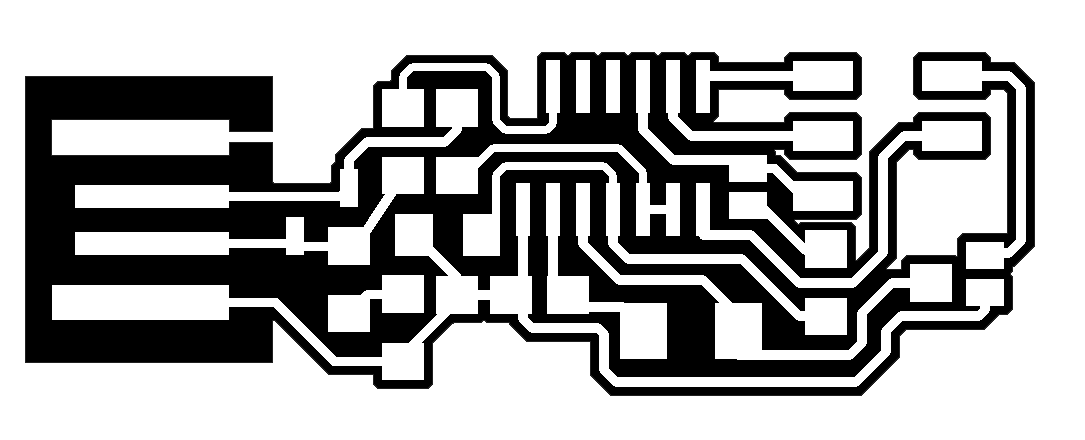 Fig.03: Board design. |
 Fig.04: Contour design. |
Before sending those designs to the mill, they needed to be converted on fabmodules.org. To fit the job to our machine, I converted Andy's .png-files into G-code. For that, Fabmodules allows to import a .png image and to choose from a large variety of different output formats - according to the machine in use. Regarding the previously tested mill properties, I made the following adjustments (see screenshot Fig.05):
|
Adjustments in output parameters:
|
Adjustments in process parameters:
|
After thus creating both gcodes for the board and the contour, I saved them to the flash drive and imported them to the computer that operates our PCB mill, a Roland MDX-40 (Fig.06).
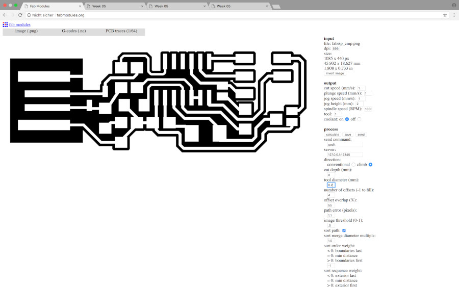 Fig.05: Screenshot of conversion parameters for board milling. |
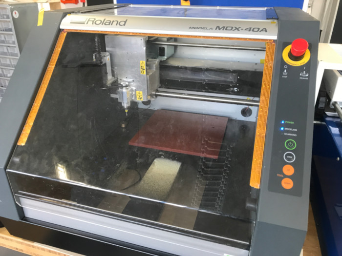 Fig.06: Roland MDX-40. |
The operating software on the computer connected to the Roland mill allows for adjustment of home positions of the X, Y, and Z axes. While X and Y are pretty straightforward to define, home position of the Z axis is somewhat critical: 1) it takes patience to find exactly the Z height where the mill just barely touches the board and 2) the board must be perfectly layed out horizontally without any flaws of wrinkles, otherwise the mill may cut too deep in some parts, or not at all in others. Fortunately, the boards had been prepared by Daniele, so all I had to do was fixing it properly into the mill (Fig.07), then setting the Z home. Of the vaious techniques to do that, I chose letting the spindle run at high speed and bring it stepwise down until it shows the first flakes from cutting into the board. The alternatives are a) using the sensor, and b) checking for connectivity with a multimeter. The sensor seems not to be the most reliable tool for the job, hence most of my classmates used the multimeter. Fig.08 shows the screenshot of our operating software, including the spindle speed set to 8,500rpm.
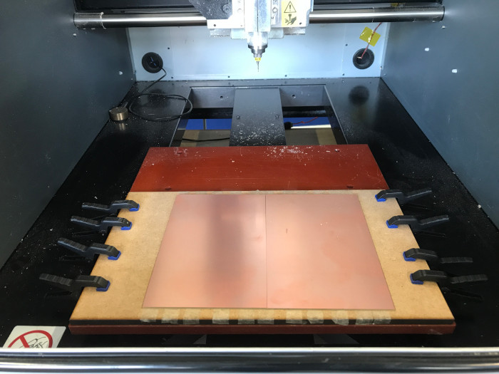 Fig.07: New board fixed in the PCB mill for cutting. |
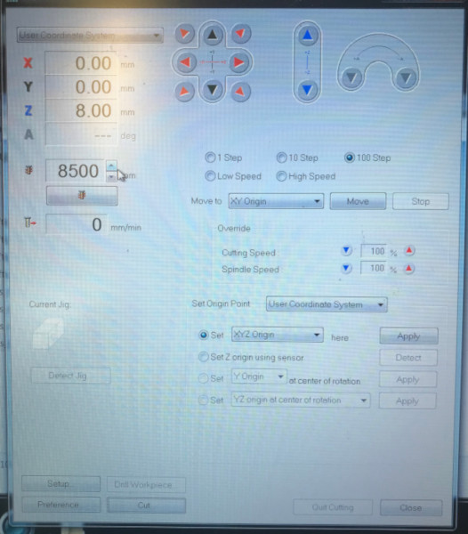 Fig.08: Screenshot of operating software. |
Between milling the traces and cutting the outline of the board, some further changes in the Fabmodules settings were necessary: 1) we had to change the tool diameter from 0.2mm to 1.0mm, 2) reduce cutting speed from 1mm/s to 0.5mm/s, and 3) change the cutting depth to 1.9mm. Of course, this means we had to change the tool physically as well, using two wrenches to losen it up (Fig.09 & 10). The outcome was quite satisfying, checking the traces for connectivity revealed that the board works (Fig.11 & 12)!
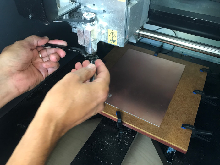 Fig.09: Tool change 1. |
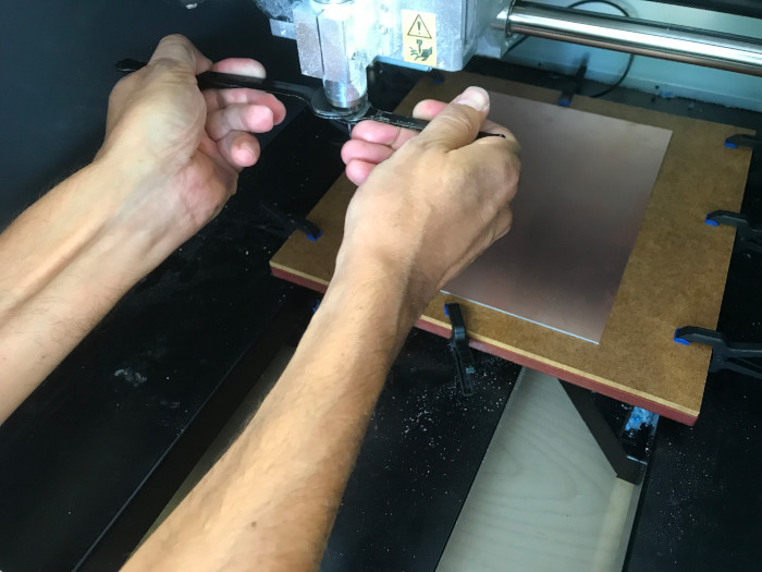 Fig.10: Tool change 2. |
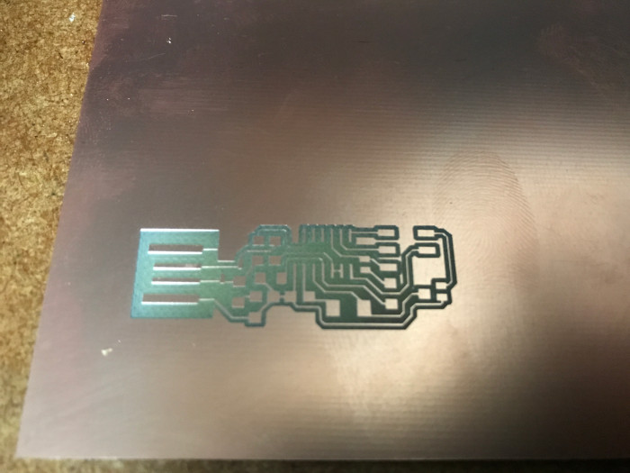 Fig.11: PCB after milling traces. |
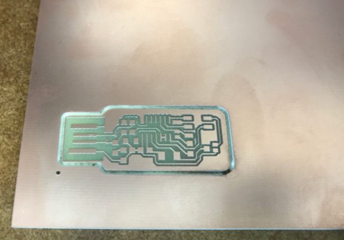 Fig.12: PCB after cutting outline. |
Update 2020
Schematic and assembly drawing allowed to make a list of material to be soldered on the ISP:
- one ATTiny44 microcontroller
- one Crystal 20MHz
- one 6-pin header
- two 49.9 Ohm resistors (R1&R2)
- one 1 kOhm resistor (R3)
- one 10 kOhm resistor (R4)
- one 0 Ohm resistor (R5)
- one 499 Ohm resistor (R6)
- two 8pF capacitors (C1&C2)
- one 0.1 µF capacitor (C3)
- one 1 µF capacitor (C4)
- two 3.3 V diodes (D1&D2)
The outcome was my first piece of soldering (Fig.13) - and testing with the multimeter revealed it to be free of short circuits!
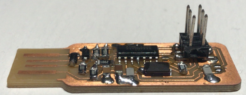
Fig.13: FabISP after soldering.
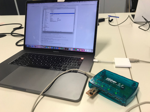
Last part of this week's individual assignment was the programming of the ISP. Following the FabAcademy instructions, this meant first to download and install CrossPack for AVR Development, then to download the FabISP firmware from the FacAcademy Webite. After connecting my ISP to check for smoke (negative!) and subsequently connecting it via Daniele's programmer (Fig.14), an adjustment in the Makefile code was still necessary (using the nano Makefile command): the hashtag was replaced from the first AVRDUDE code line to the second.
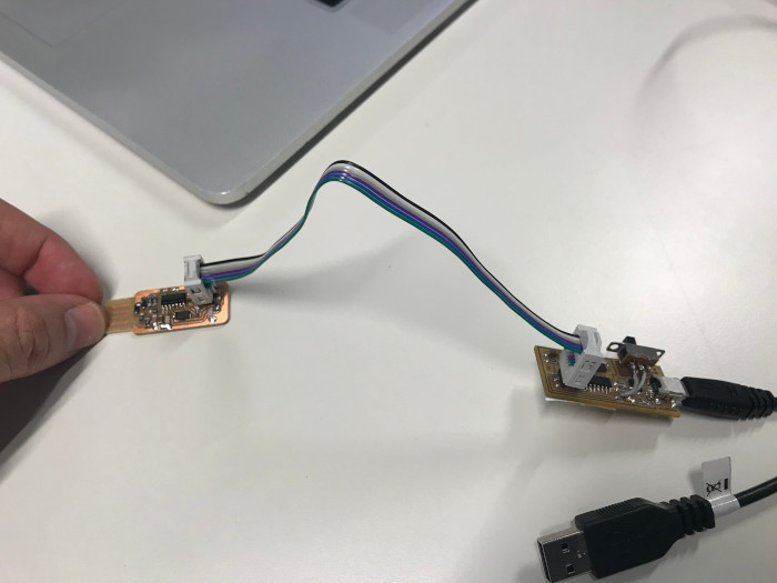
Fig.14: My FabISP connected to Daniele's programmer.
After that, my Macbook found Daniele's bootloader, but the make fuse command did not connect to my ISP. This was a result of incompatibility with my 2016 version of the MacBook Pro (High Sierra 10.13.6). Various attemps failed, in the end we had to run make fuse from an older MacBook to successfully set the fuses (Fig.15). Last but one step was running the make program command to finish the preparation of the ISP (Fig.16). Finally, the two jumpers on the ISP could be removed and my own programmer was even recognized at the USB port of my own computer (Fig.17)!
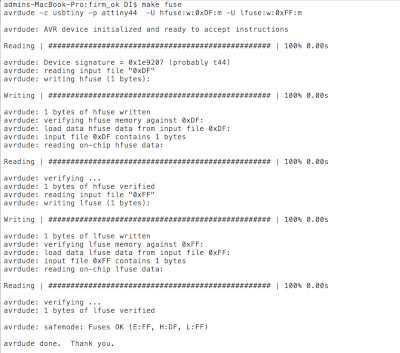 Fig.15: Terminal response after running make fuse command. |
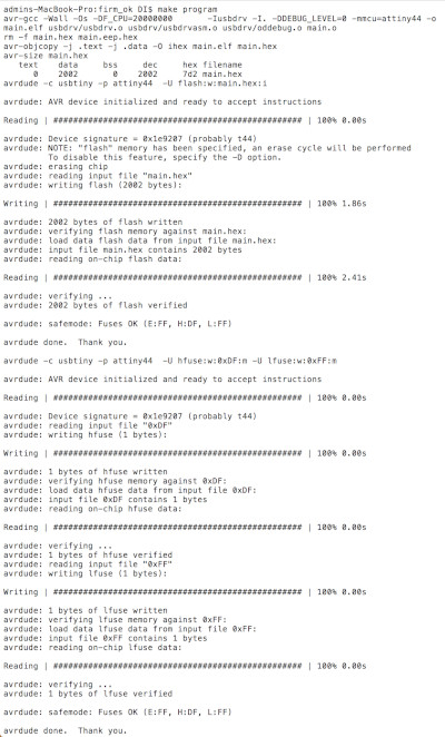 Fig.16: Terminal response after running make program command. |