Computer-Controlled Cutting
Week03
The starting point for my introduction to Computer-Controlled Cutting was yet again the struggle with DraftSight first, then with Fusion360 (F360). After some trial and error I managed to make a parametric design of one single piece of a press-fit kit (Fig.01); the width of the intentations are adjusted to the 4mm thickness of the cardboard. I exported the sketch from F360 into DXF-format which allowed for smooth import into Rhino on our computer that operates the laser cutter (Fig.02). For the cutting I chose previously documented vector settings of 90:50:70 (Power:Speed:Frequency). The first cut looked alright, thus I continued with a second run of 24 pieces with the same settings. Unfortunately, the cuts did not go through (Fig.03), I will have to repeat the operation.
 Fig.01: Parametric sketch for press-fit kit in Fusion 360. |
 Fig.02: Rhino screenshot of the laser cutter job. |
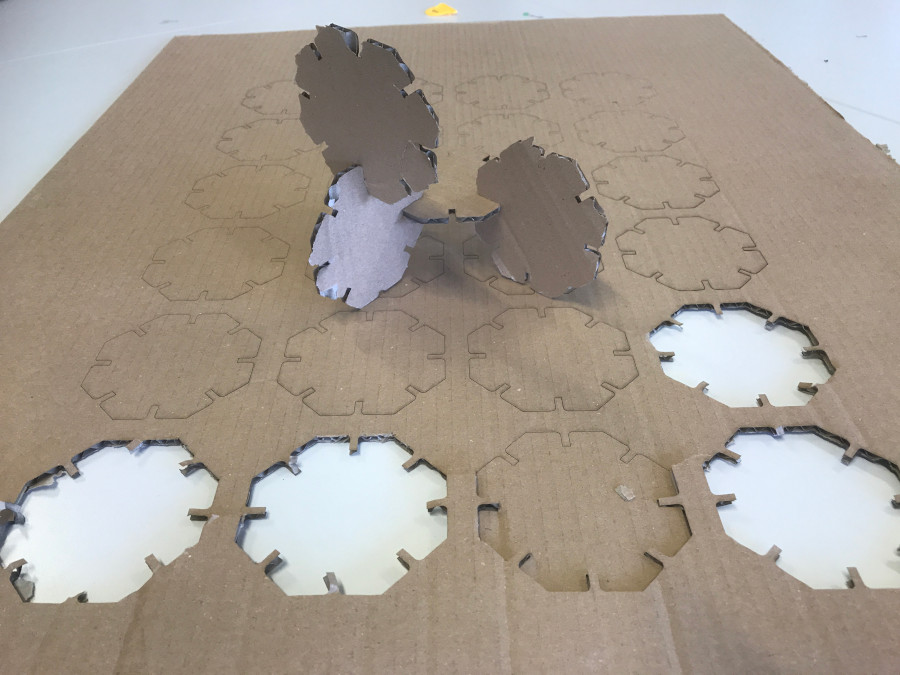 Fig.03: Unsufficiently cut press-fit pieces. |
Before the cutting actually started, of course I was briefed on how to operate the system. Figures 04 and 05 display the control panel and the device for adjusting the focus point. This knowledge allowed me to proceed with the kerf measurement for 2mm MDF as my part in our group assignment. I sketched a rectangular comb design with 10 perpendicular cuts and one additional horizontal cut in the center in Rhino. Figure 06 displays the result: I received one uncut rectangular piece as my reference (top) plus 11 small pieces from 10 perpendicular cuts, reduced in width by the kerf. The difference in width is visible on the left side of the foto; it amounts to 1.35mm, hence the width per kerf is 0.135mm.
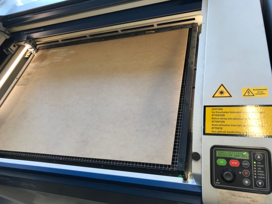 Fig.04: Laser cutter control panel. |
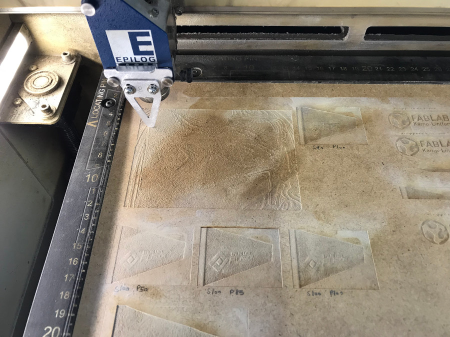 Fig.05: Adjusting the focus point for the laser cutter. |
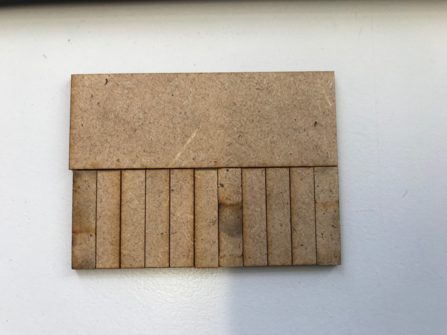 Fig.06: 2mm MDF cutout for kerf measurement. |
Update 2020
For this year's group assignment, Ferdi introduced a different approach to measuring our cutter's kerf: designing and lasercutting a "comb" with differently sized and labelled indentations (Fig.07 and 08). After saving the sketches in .dxf format and exporting to Rhino, we tried color mapping (Fig.09) to first engrave (settings 100% speed, 65% power, 50% frequency), then cut (settings 8% speed, 100% power, 10% frequency). Various speed reducing repetitions were necessary for us to find out that we had a bug in our color mapping software and that we had to do both steps separately from the General properties window (Fig.10). Those range from 2.75mm to 3.00mm and serve to find out which of them fits best to the wood sheet we work with.
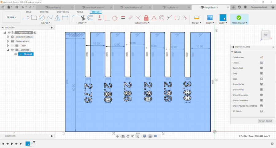 Fig.07: F360 design of the kerf comb. |
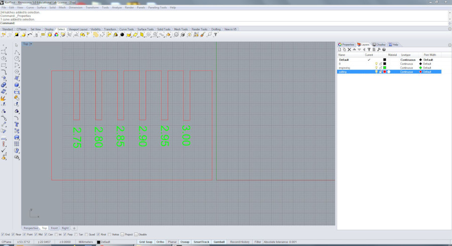 Fig.08: Kerf comb after cutout. |
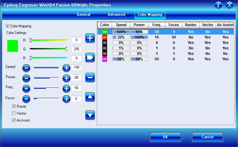 Fig.09: Color mapping window. |
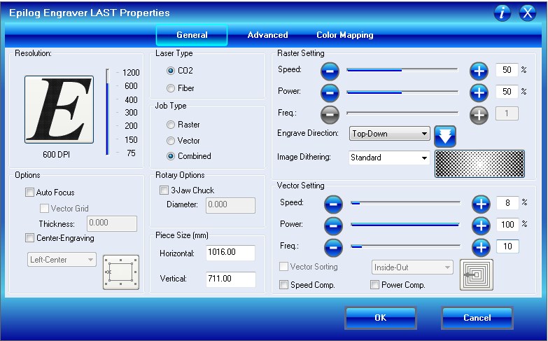 Fig.10: General properties window. |
We found the best fit for a 3mm MDF sheet at the 2.8mm indentation (Fig.11) - which indicates our kerf to be 0.2mm. I used that value for the design of my press-fit model of a piece of furniture I want to make in a later course day on our CNC mill.
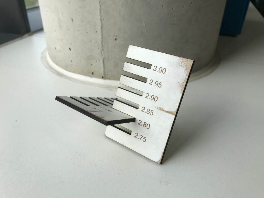 Fig.11: Fitting the wood sheet into the best fitting pocket. |
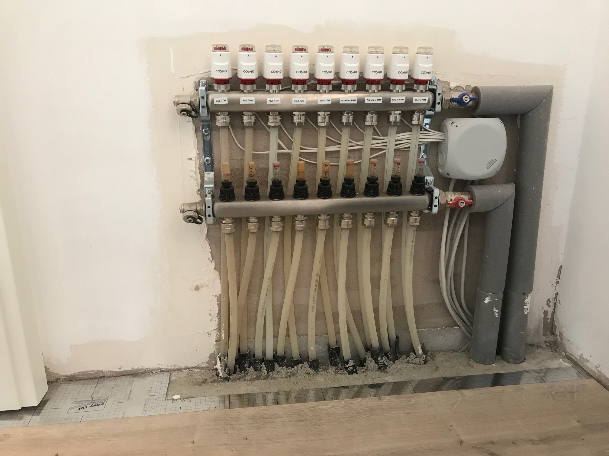 Fig.12: Control unit for heating circuit. |
The piece of furniture is what we call an "Abkastung" (encasing) for the control unit of our heating circuit (Fig.12). Regardless of the exact measures (and easy to adjust exactly later thanks to parametric design), this Abkastung needs to have some holes to fix it to the wall plus two holes to maintain access to the vents for incoming and outgoing water.
Starting with the front panel, I designed a sketch in F360 with the corresponding holes (Fig.13), then extruded the sketch to 3mm thickness and added the pockets for the press-fit connectors. For that, I used a rectangle at 12.5mm distance from the upper left corner which I extruded into body1, my front panel (Fig.14). To repeat the cutout, I used the Rectangular Pattern command with 4 repetitions along the upper edge of the front panel, later did the same along the vertical edge (Fig. 15). Following Danieles advice, width and depth of those pockets were defines through the Change Parameter dialog box in F360: starting with the original values of 25mm width and 3mm depth, this allowed me to adjust all the pockets to the kerf (i.e. from 25mm to 24.8mm) simultaneously simply by changing the values in the dialog box (Fig.16). I finished the design by completing the top and the side panel, following the same steps as in the front panel design (Fig.17).
 Fig.13: Front panel sketch of encasing for heat circuit control unit. |
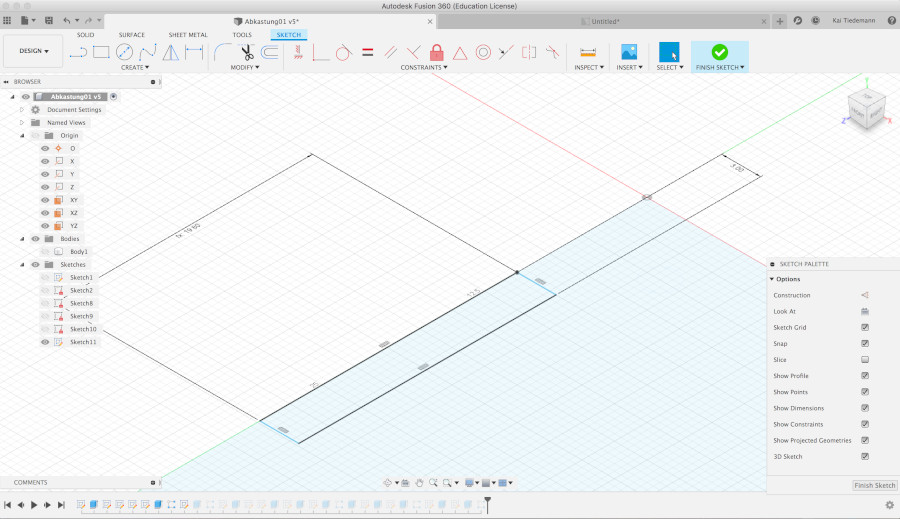 Fig.14: Front panel sketch. |
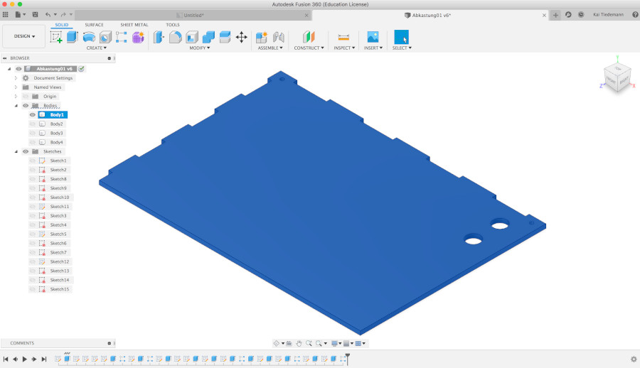 Fig.15: Extruded front panel with press-fit pockets. |
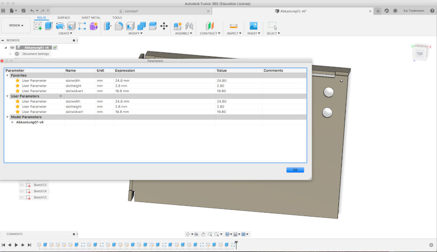 Fig.16: F360 change parameter dialog box. |
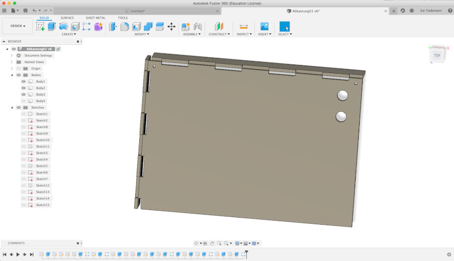
Fig.17: Complete encasing in F360.
The model still needs to be cut, I will push an update to my repo as soon as I have the foto (Fig.18).