Individual assignment:
Measure something: add a sensor to a microcontroller board
that you have designed and read it.
Group assignment:
Probe an input device's analog levels and digital signals
Brief about used sensors
I decided to integrate the final project in this week, so what I will do is make a demo of the sensors I will use in my final project and
connect them with output devices week .So: Input ,output devices ,networking and interface assignments in one big project.As
Proff. Neil advised I will work in spiral loops.
The sensors that I will use:
Earlier I planned to use Hall Effect sensor to detect metal ,IR Sensor to detect glass,ultraSonic sensor to
detect moving object plus capacitive sensor to detect plastic and paper.
After a long reaserch , I found out a capacitive proximity sensor that could do the function of the previous
four sensors,which will save a lot of hassel.
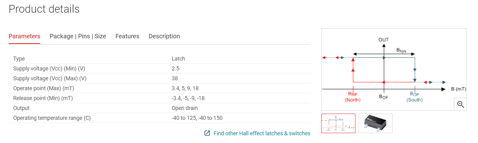
Here is a brief about the sensor and how it works:
A Hall effect sensor is a device that is used to measure the magnitude of a magnetic field. Its output voltage is directly proportional
to the magnetic field strength through it. Hall effect sensors are used for proximity sensing, positioning, speed detection,
metal detection and current sensing applications.
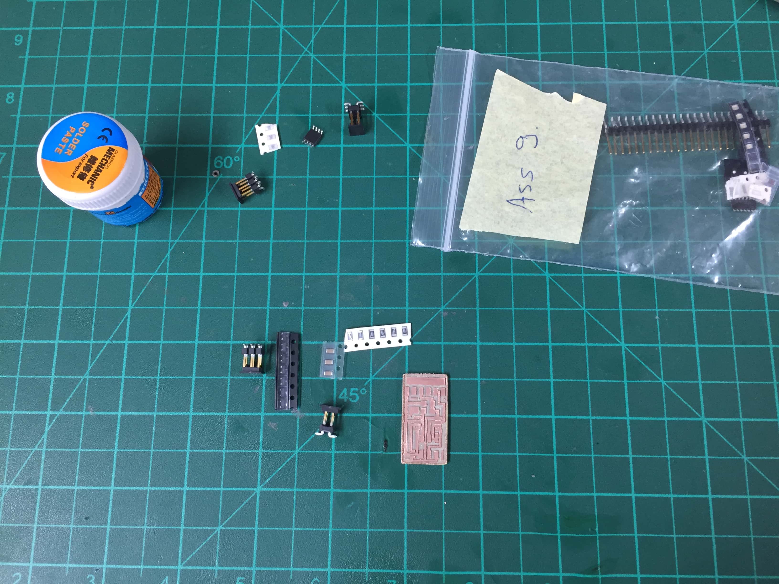
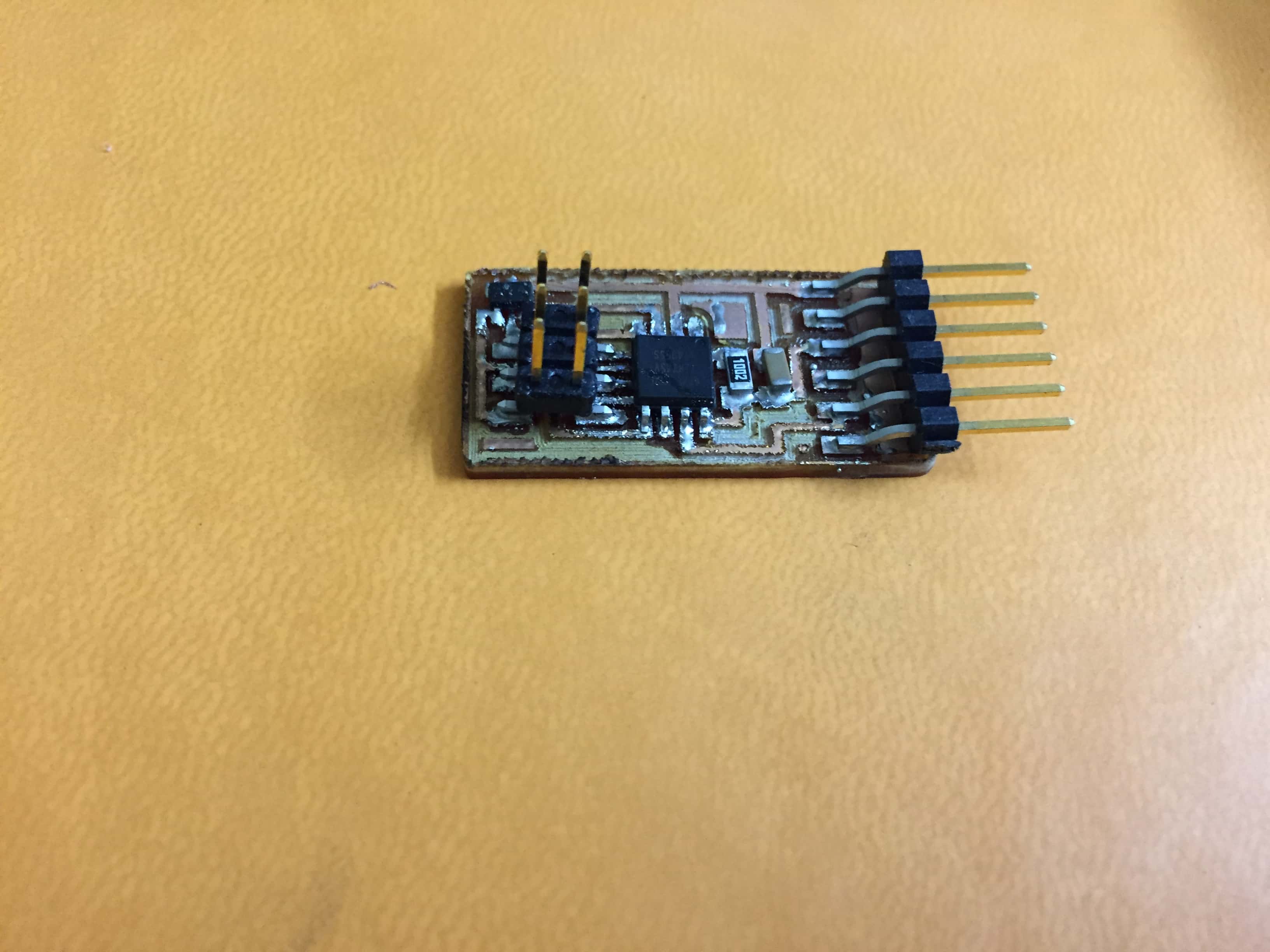
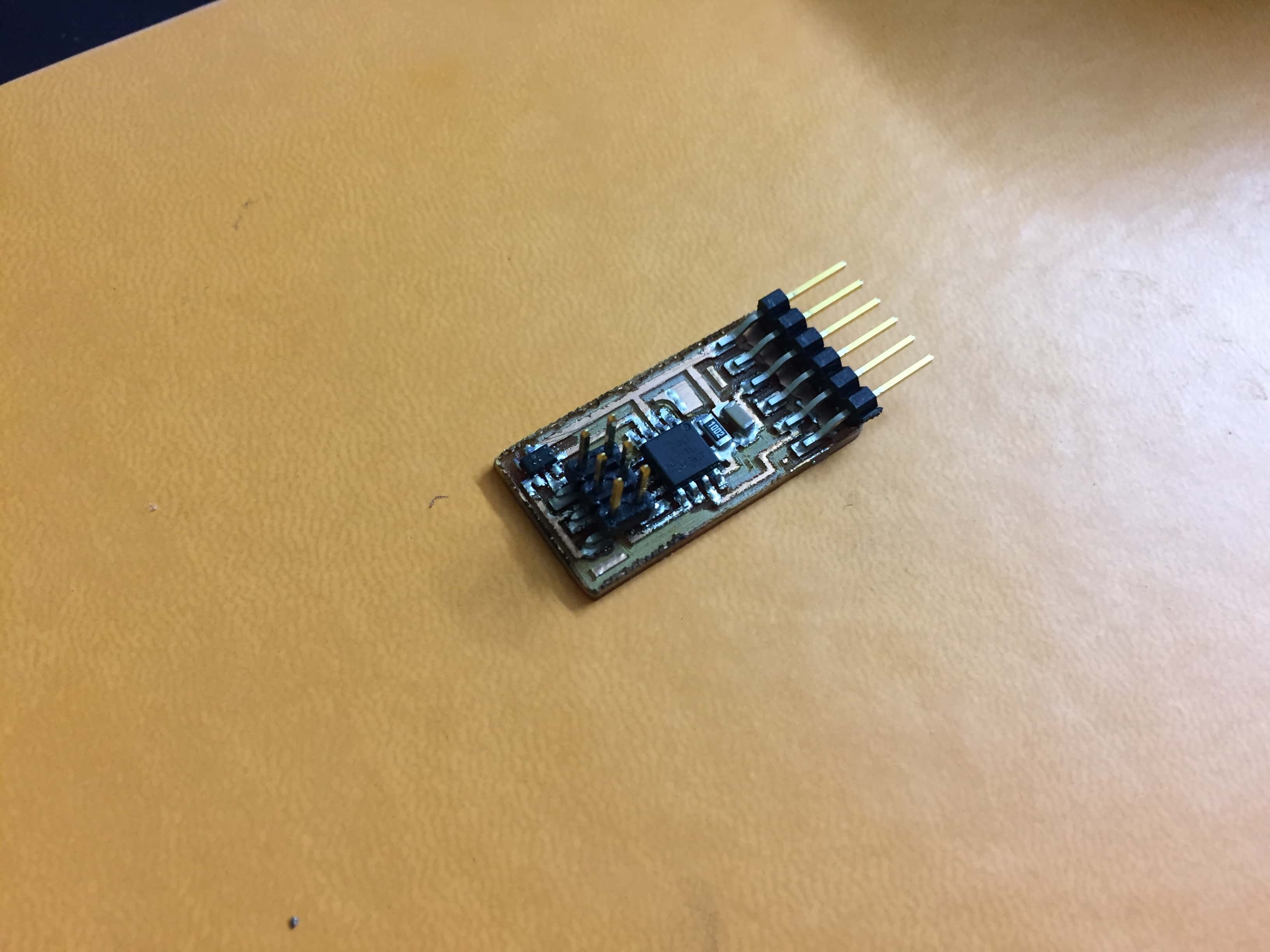
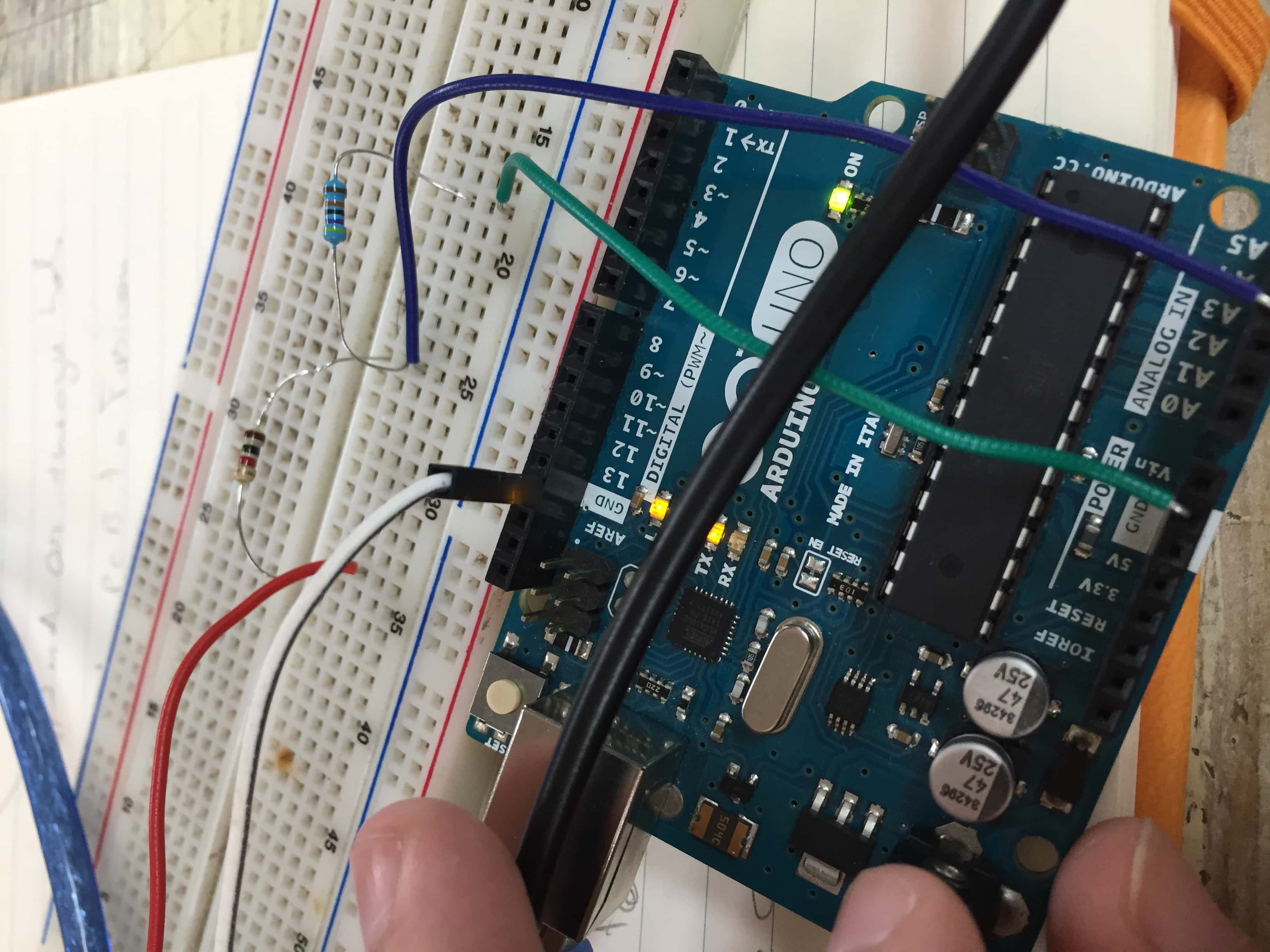
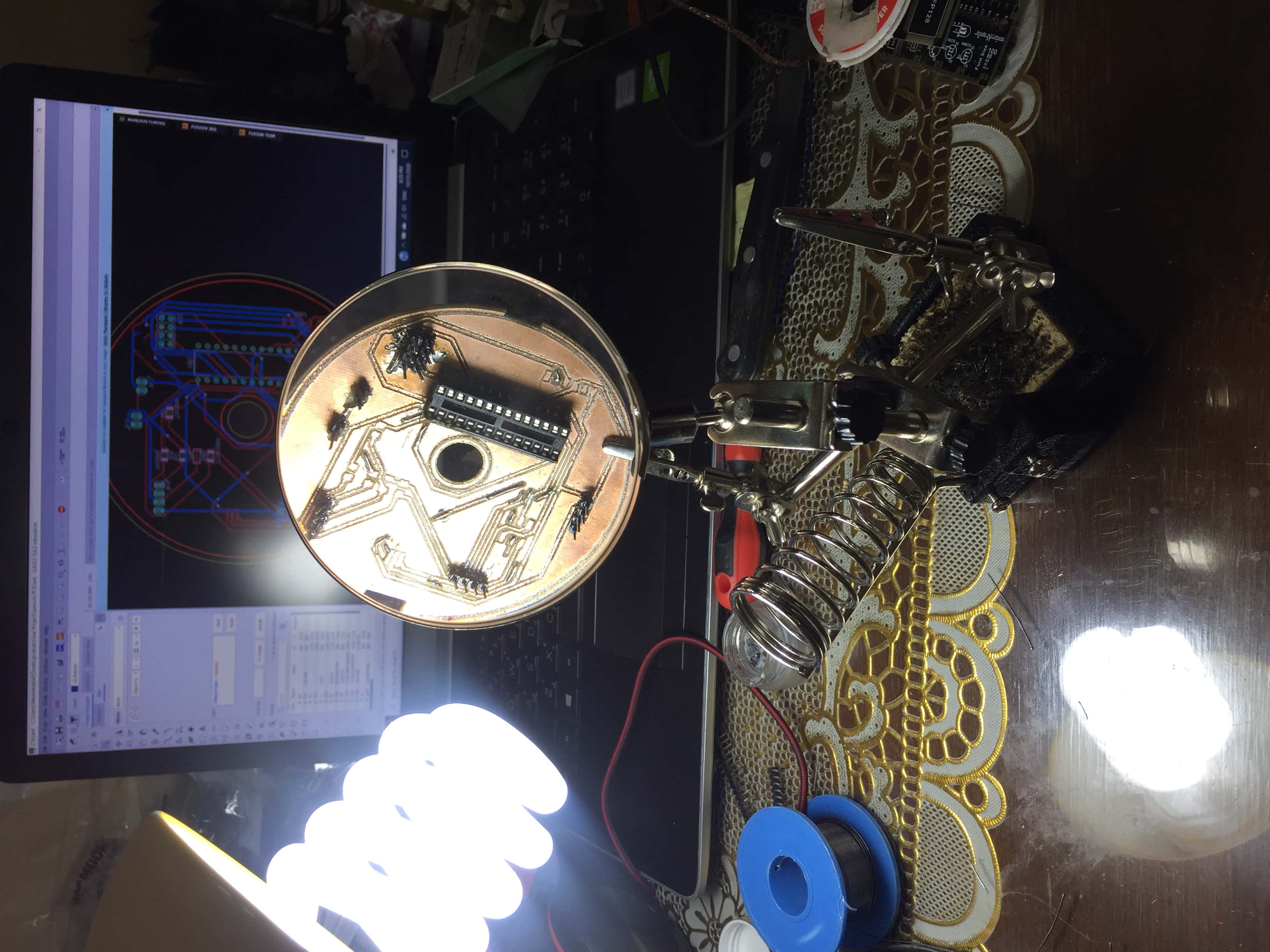
To begin with I did the design as it is ,the one on Fab Academy website to test it and get familiar with the sensor.So I
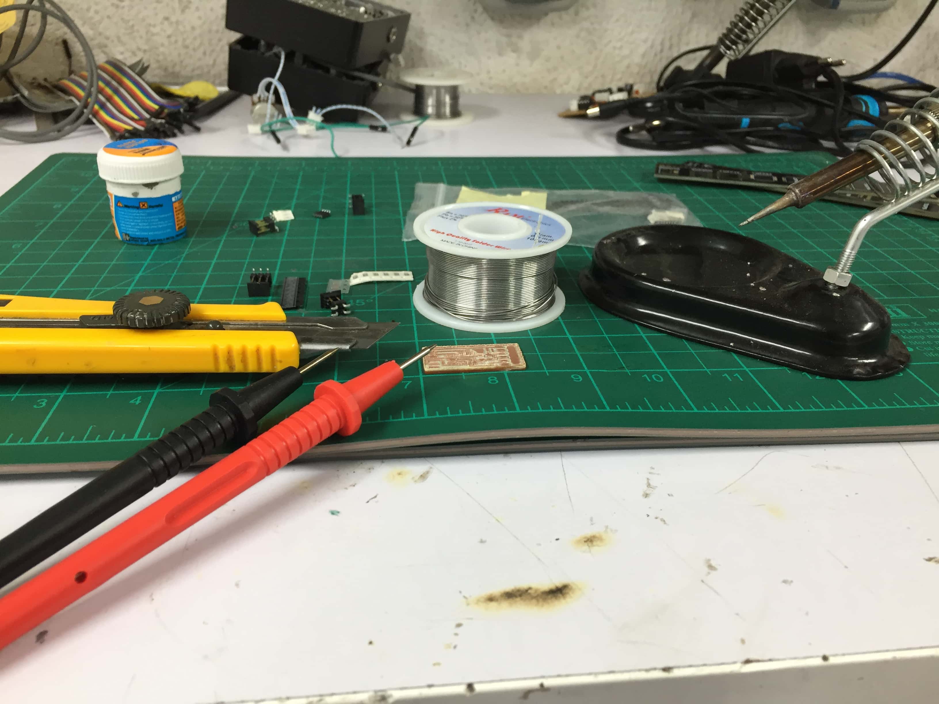
did the milling and the soldering.
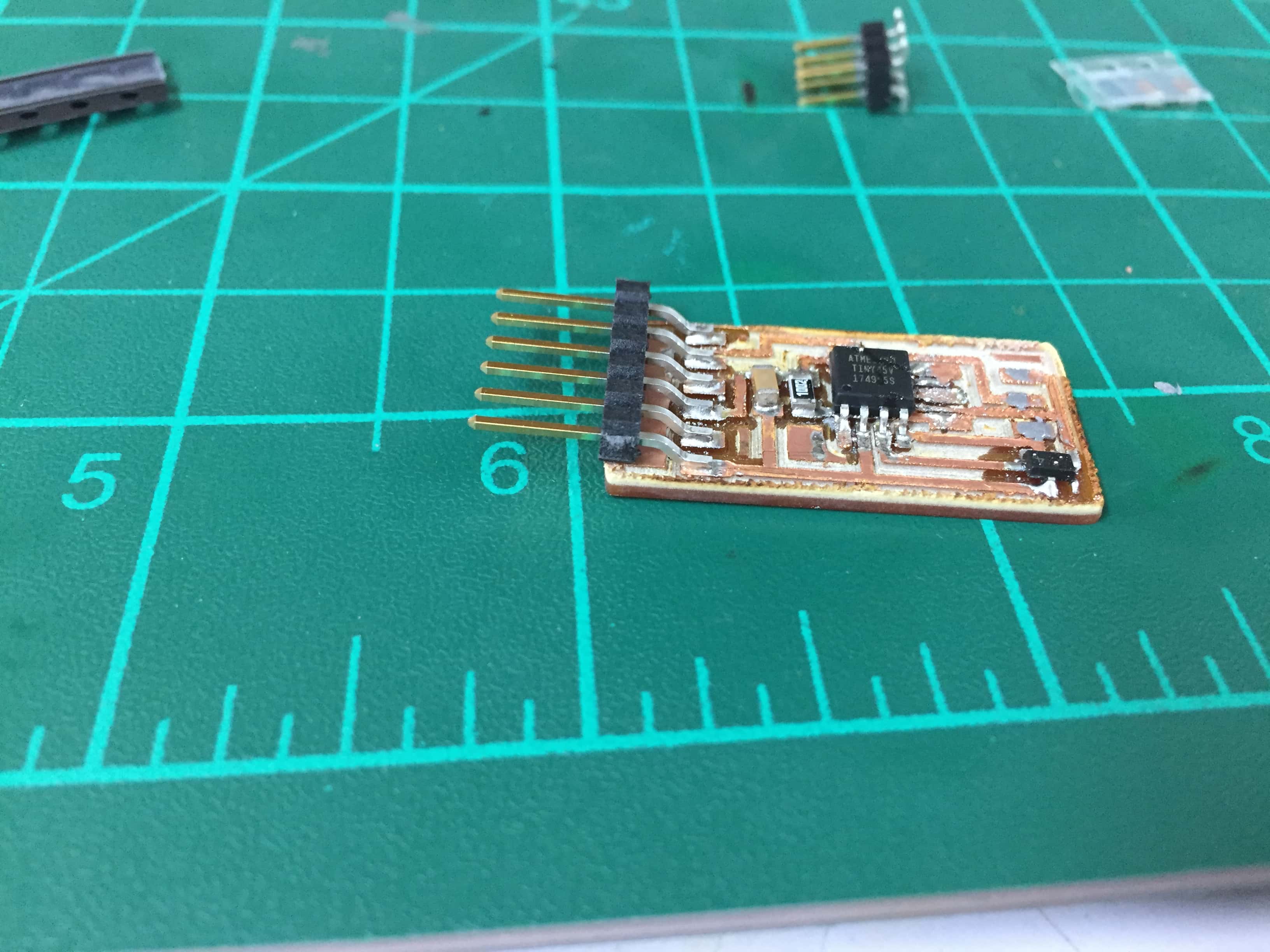
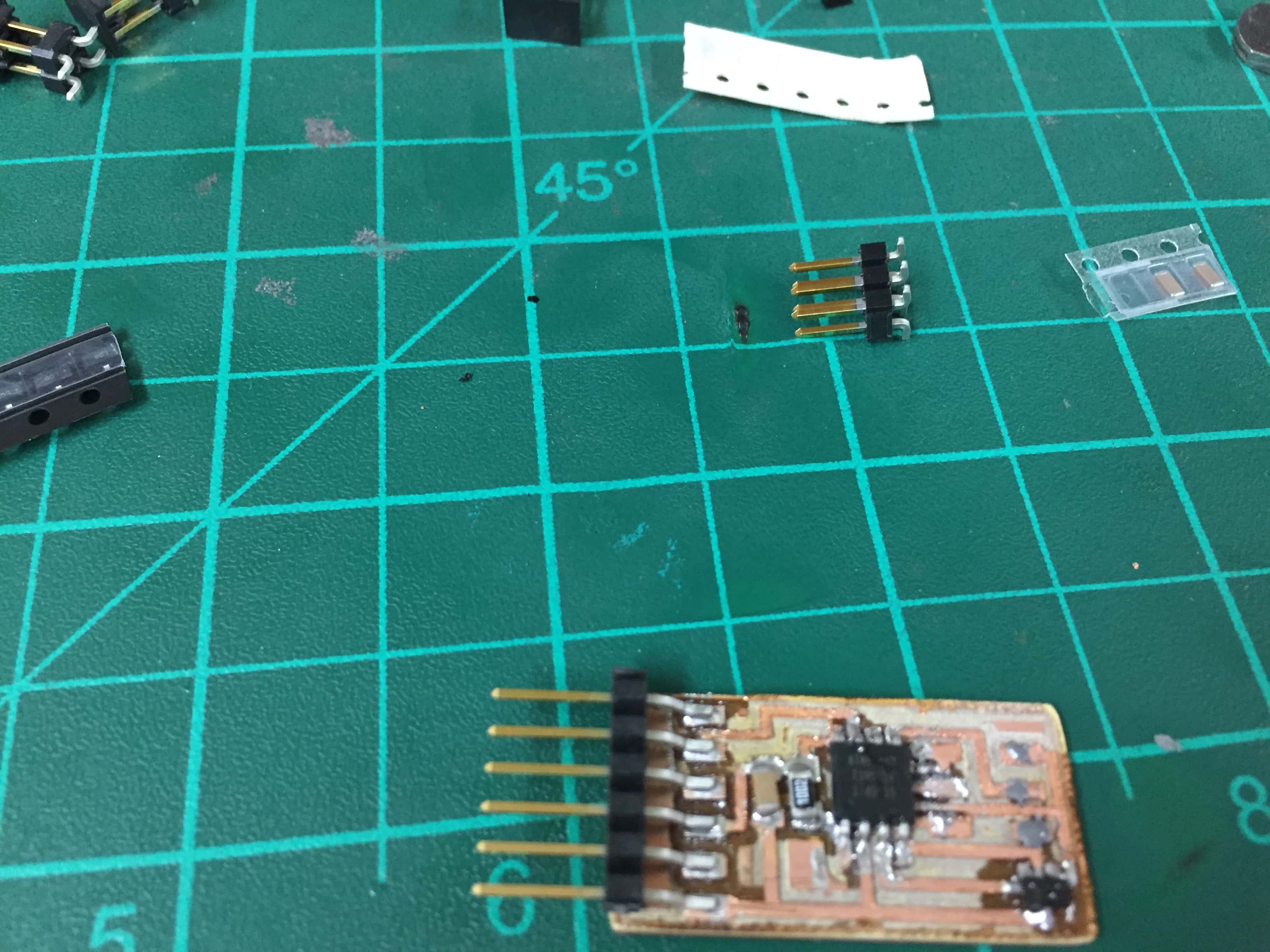
So this is my first iteration :
Then I programmed it using Atmel ICE and it was succsseful .
But There was no readings:
I doubted that the sensor is dameged or mounted wrong.
How to design a PCB for sensors
To design a PCB in general or a PCB for sensors there are some common points to take in consideration:
1)First you have to decide the exact function of the PCB :to sense , to operate motors or to do other functions
,then you start searching for the available components and tools "givens",after that we figure out the unkowns.
EX:Let's say for example we want to sense distance and we have an Ultrasonic sensor,
we search for the operating voltage and current then search for the appropriate microcontroller or IC.
2) For the microcontroller for example or an IC that process the information:"DATASHEET ,DATASHEET and DATASHEET" why ?? because:
-You will know the Volt,Power and current to operate it .
-The ports'types.
-The necessary connections to operate it.
3) Any PCB must have voltage source and common ground "VCC" and "GND".
4)If we're going to attach a sensor we have to know ,is it analog or digital to connect it to the right port.
5) You definetly have to know the physics behind the sensor as for the previous example:The Ultrasonic
sensor ,it has a sender port that sends waves and a reciever port so whenever
a wave is sent it hits an object for example and get back to the reciever port,and the output signal represents
the time of the wave that went and got back,if we want to know the distance it is not the number that the sensor gives directly ,it is D=V/t
where D is the distance,
t is time and V is the speed of the wave ,divided by 2 because t represents the time of wave going and comming back.
6) We can't forget the pull up /pull down resistors and the bypass capacitor if necessary.
7) Take in consideration the reset pin connected to the VCC with a resistor.
This is just a brief there is a lot to know about PCB design depending on the function and the available tools and components.
My Sensors' PCB
I had to be really careful designing this PCB ,as it is the master that takes the readings
from the sensors ,process the data and give orders to the rest of the system,
the design was a bit tricky as this PCB combines many sensors at once,each has it's own properties.
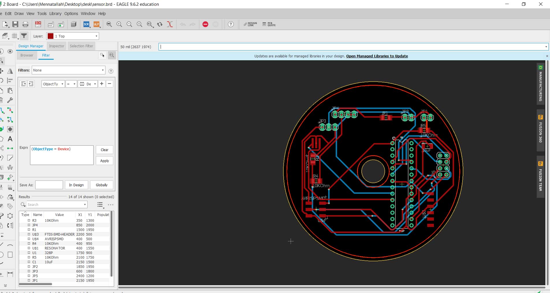
So I began by making a schematic for my PCB NB. this is the sensor PCB that I will use in my final project.I will use :
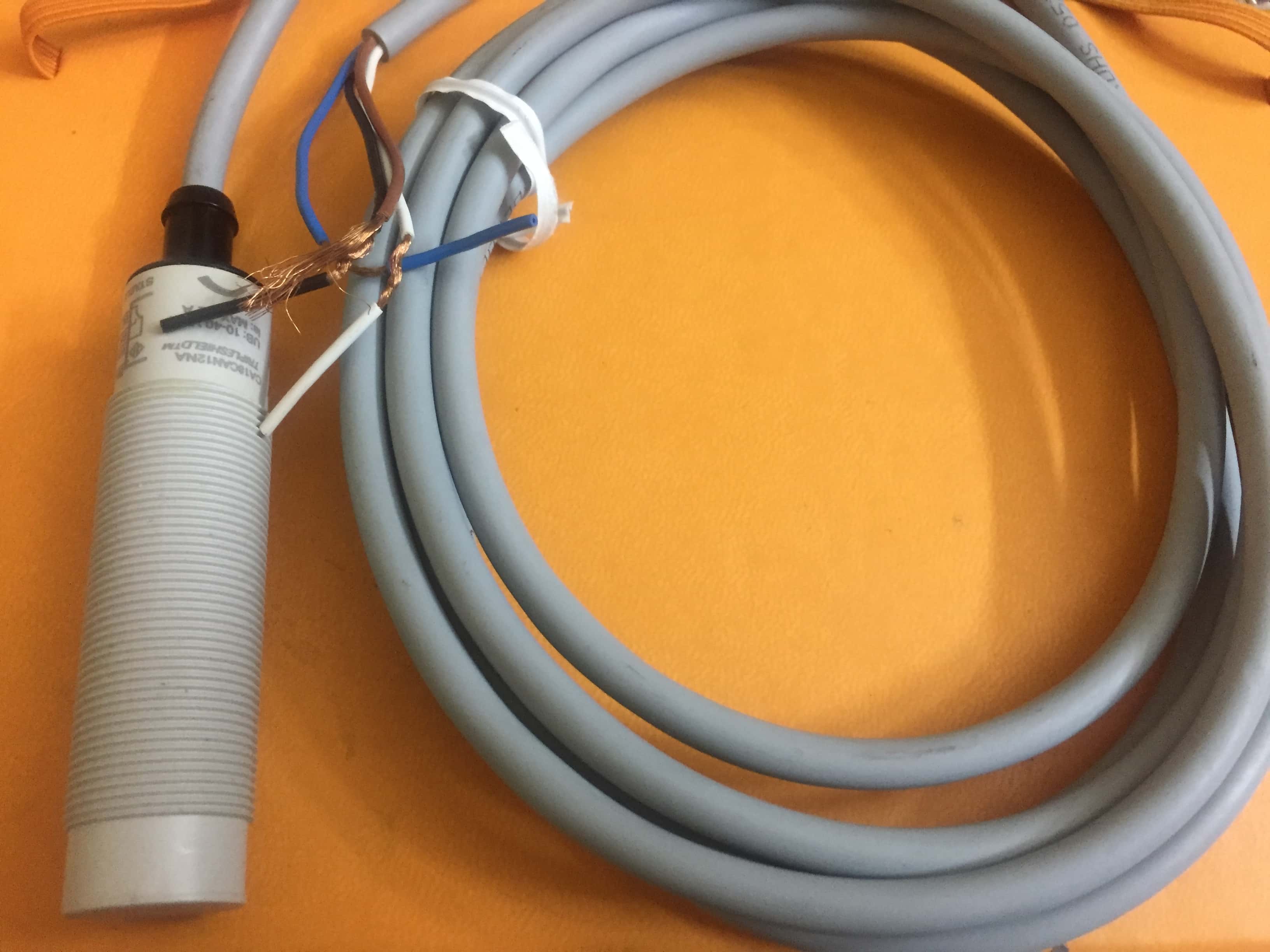
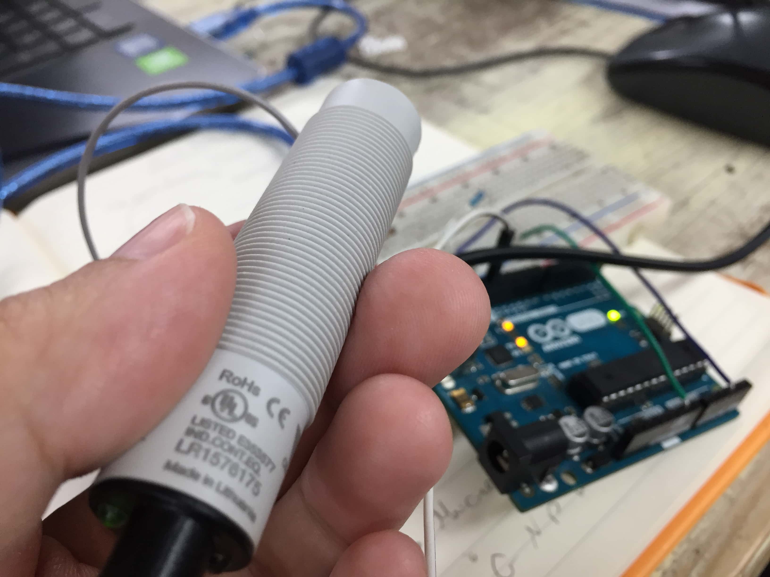
1) Capacitive proximity sensor.
- It operates on 12 volt, it is an analog sensor.
-Within the capacitive proximity sensor is one plate of a capacitor – the target serves as
the other plate. The air gap between the sensor and the target functions as the dielectric. The plate that is internal
to the sensor is connected to an oscillator circuit that is used to generate an electrostatic field.Depending on the type
of proximity sensor, sound, light, infrared radiation (IR), or electromagnetic fields may be utilized by the sensor to detect
a target. Proximity sensors are used
in phones, recycling plants, self-driving cars, anti-aircraft systems, and assembly lines.
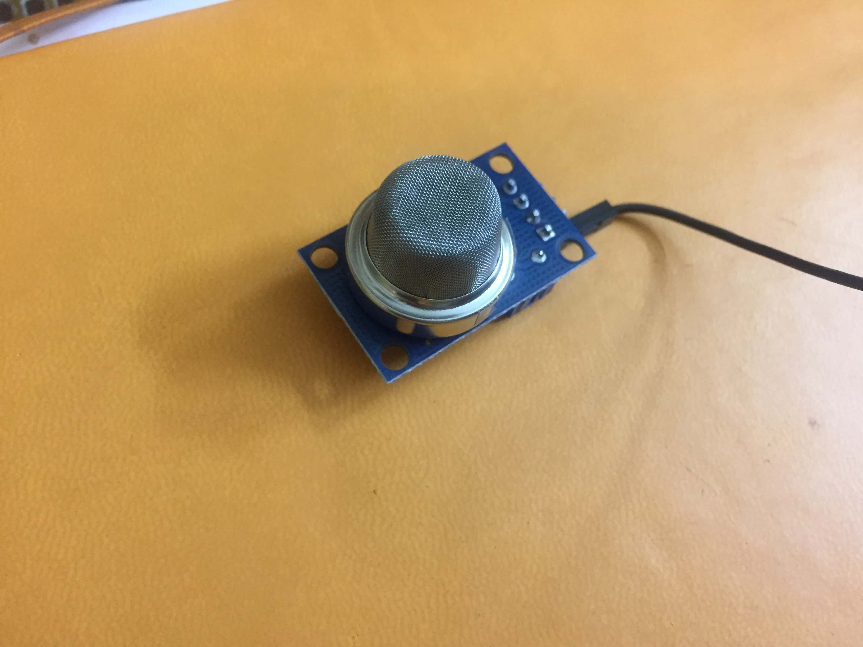
2)Methane sensor.
-It operates on 5v and it can be wired to be analog or digital.
-A Catalytic Bead Methane Sensor works as a simple Wheatstone bridge circuit, where an active
and reference filament wound from platinum wire with a palladium based catalyst changes the proportional resistance between the active
and reference bead of the methane sensor in proportion to the amount of methane detected in a background of air.
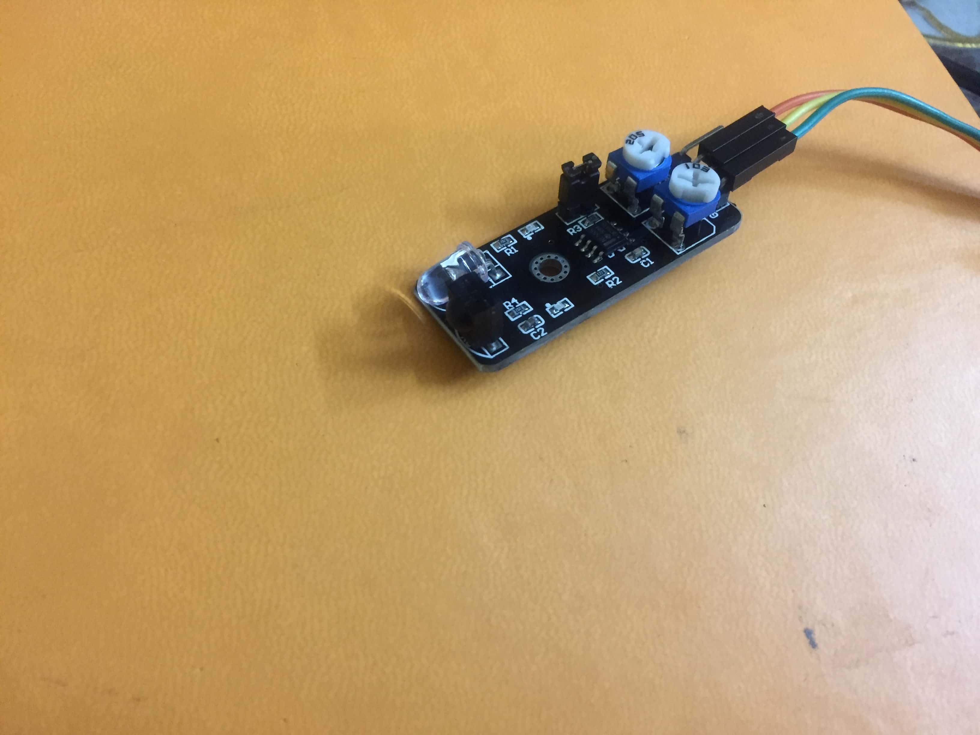
3)IR sensor.
-It operates on 5V,it is a digital sensor.
-Active infrared sensors both emit and detect infrared radiation. Active IR sensors have
two parts: a light emitting diode (LED) and a receiver. When an object comes close to
the sensor, the infrared light from the LED reflects off of the object and is detected by the receiver.
So there is a problem that the microcontroller I'm using which is ATmega328P works on 5 V and the
proximity sensor works on 12 V.Our mentor proposed a solution which is
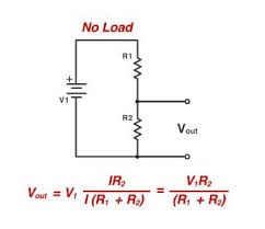
Voltage divider:
A voltage divider is a simple circuit
which turns a large voltage into a smaller one. Using just two series resistors and an input voltage, we can create an output voltage that
is a fraction of the input. Voltage dividers are one of the most fundamental circuits in electronics.
So the PCB will have
two voltage sources one which is 5V to operate the microcontroller and the two sensors"IR and Methane" and the other voltage source
is 12 V to operate the proximity sensor.
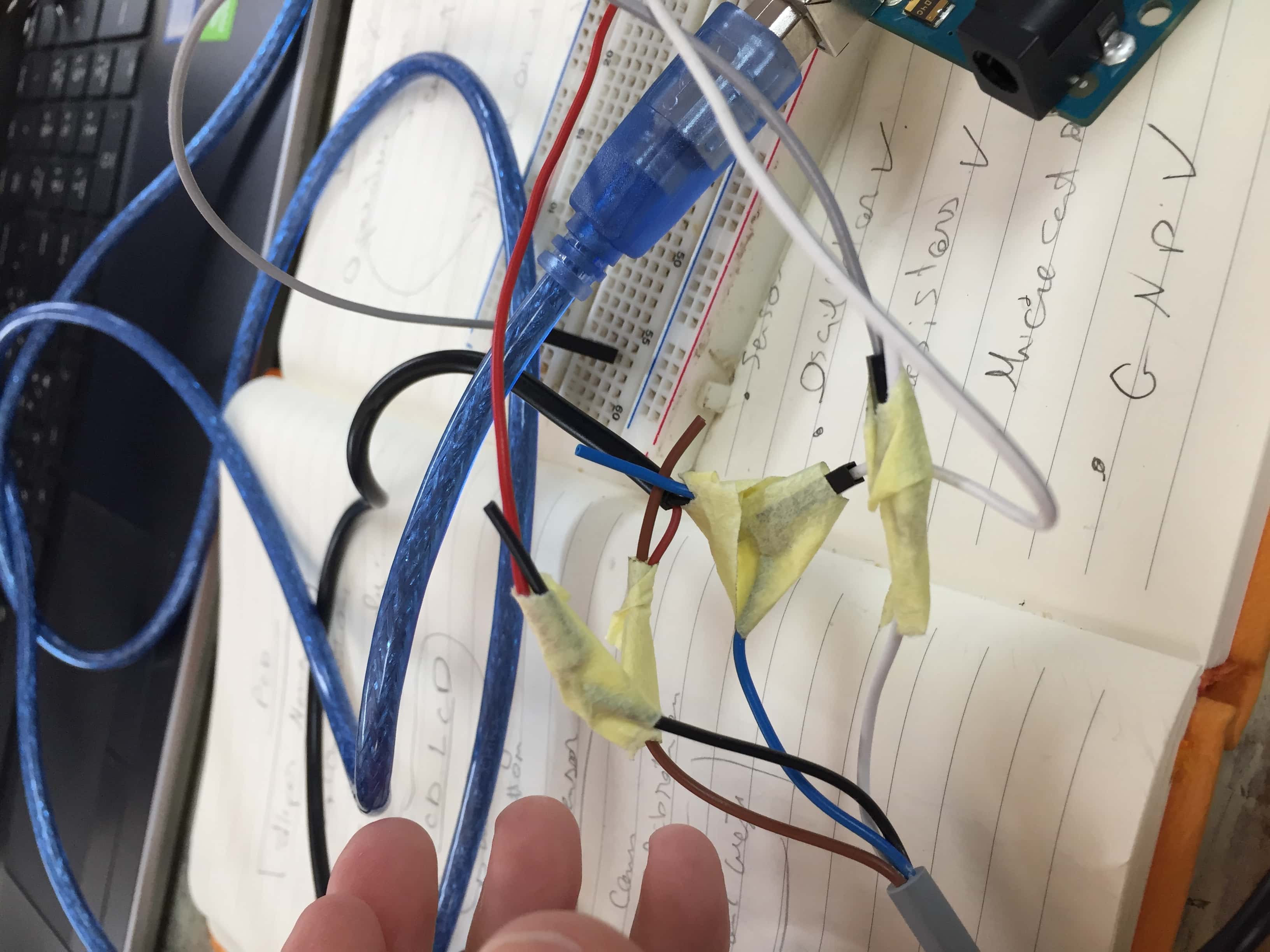
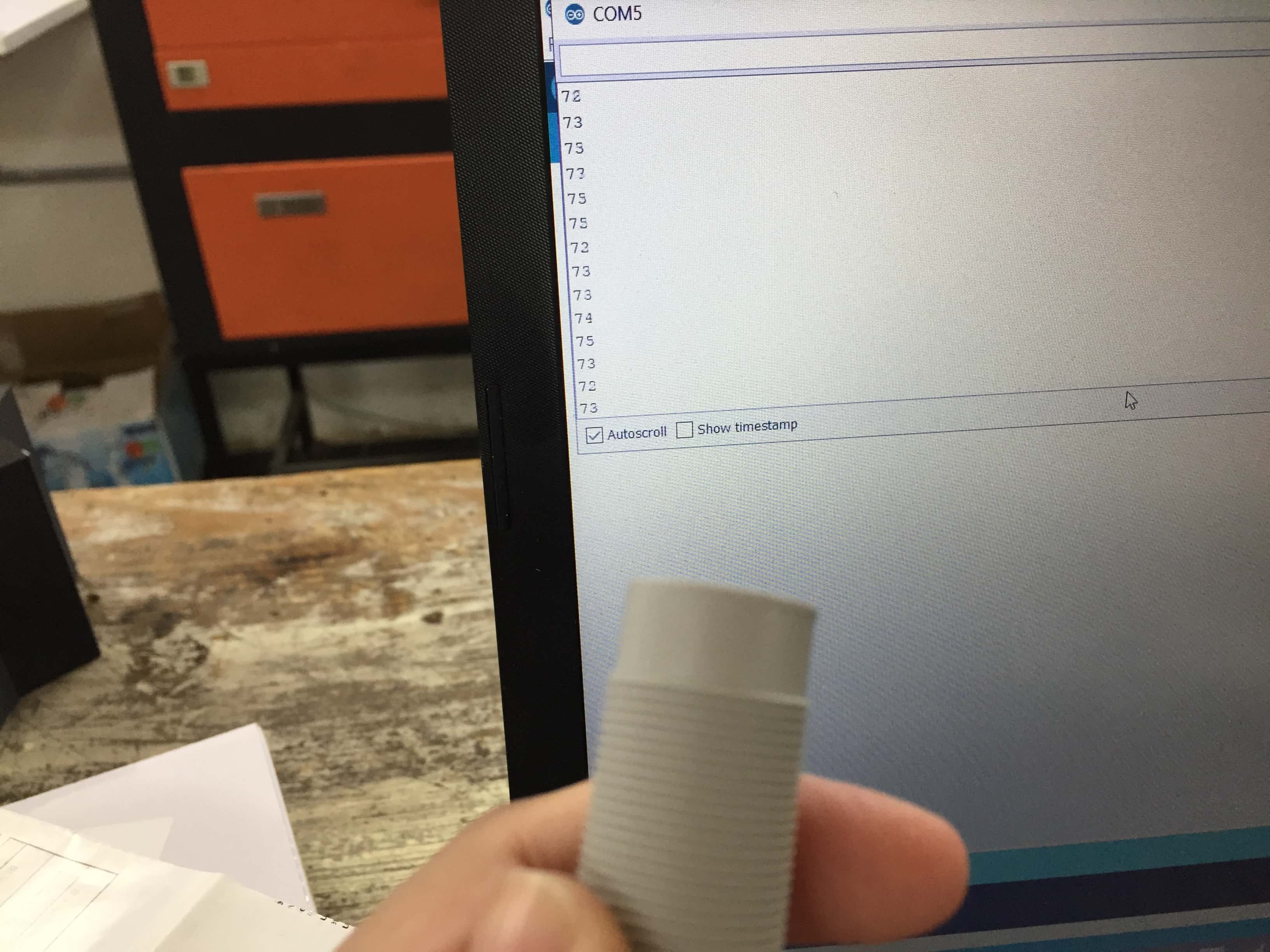
I tried all the sensors with Arduino UNO and it worked.
I should connect the AREF and the AVCC to 5V as voltage comparator.Also I added pins for ISP ,FTDI and took in
consideration connections for SPI protocol which will be explained in details in the Network and communication assignment.
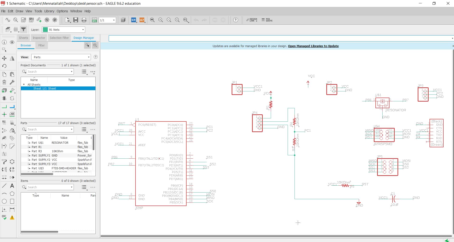
Here is the schematic and the PCB layout:
List of components
-Atmega328P:microcontroller.
-Socket for the microcontroller.
-20MHZ Crystal:to synchronize the PCBs.
-3* 1Kohm resistor:for the voltage divider and pull up resistor.
-1*10Kohm resistor.
-1*10uF capacitor:bypass capacitor.
-ISP junction.
-FTDI junction.
-Pins.
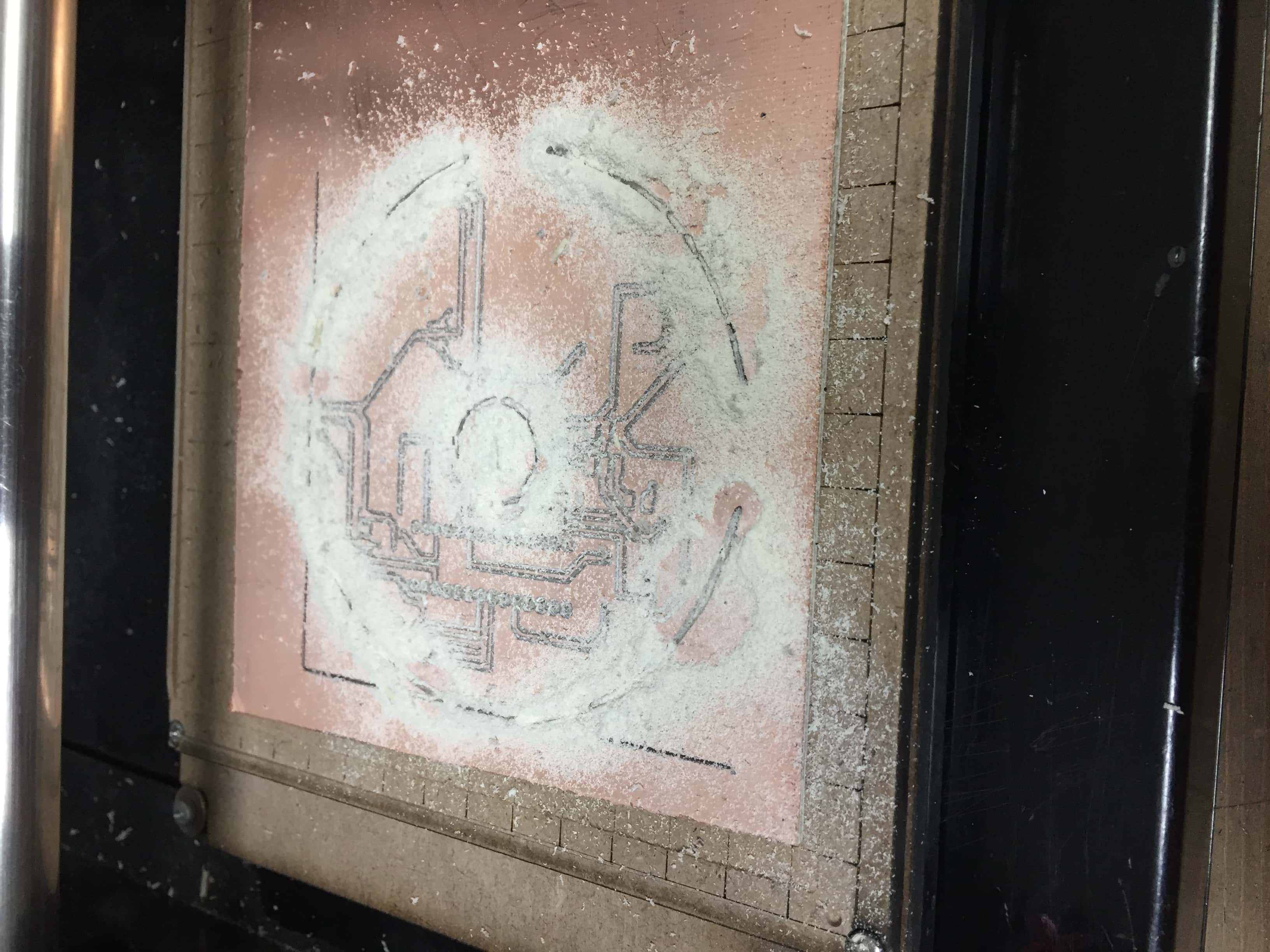
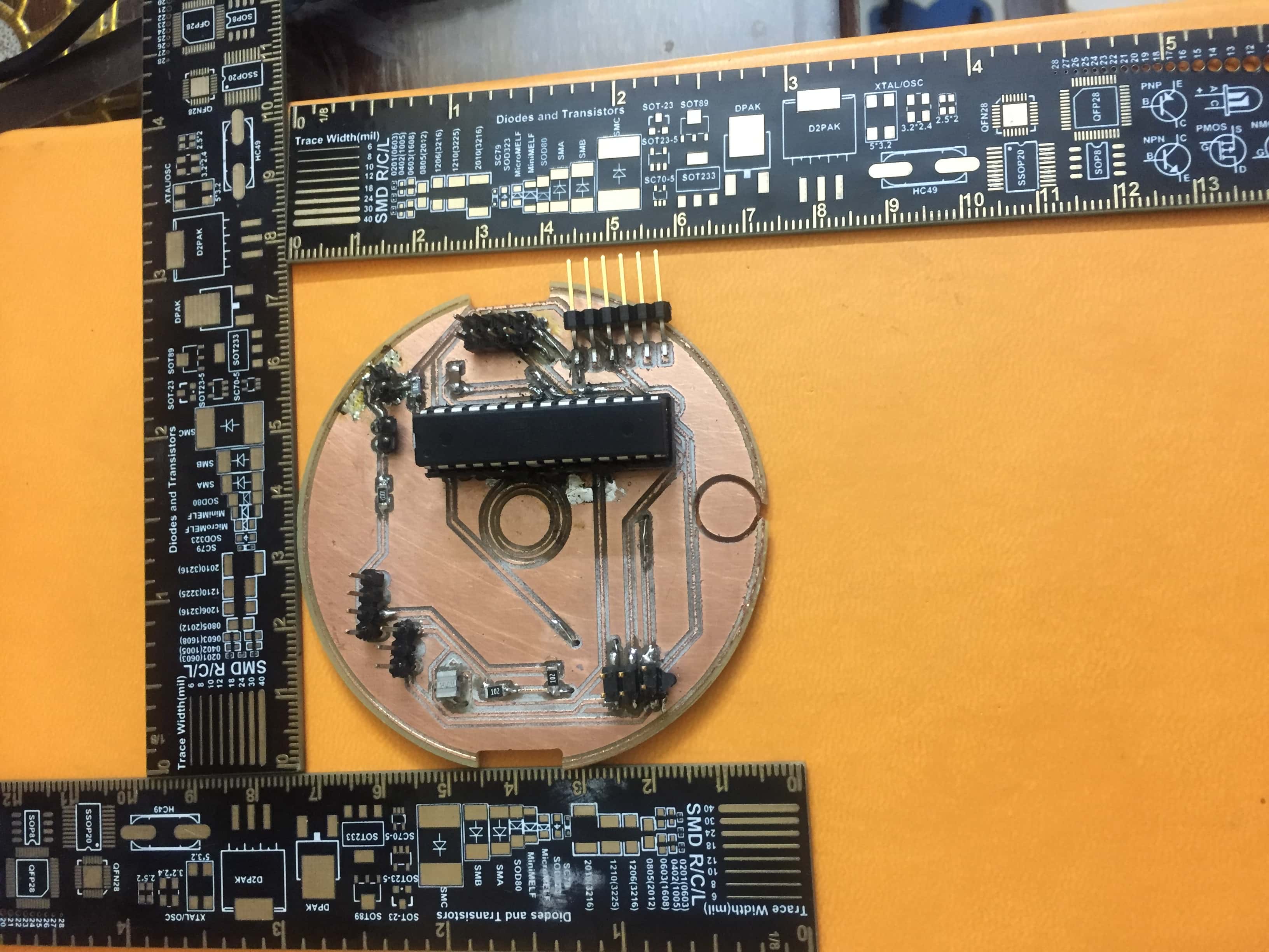
Milling
For the milling I made the PCB in a particular design which requires more considerations while milling ,
it is expalined in details in the Output devices assignmnet.
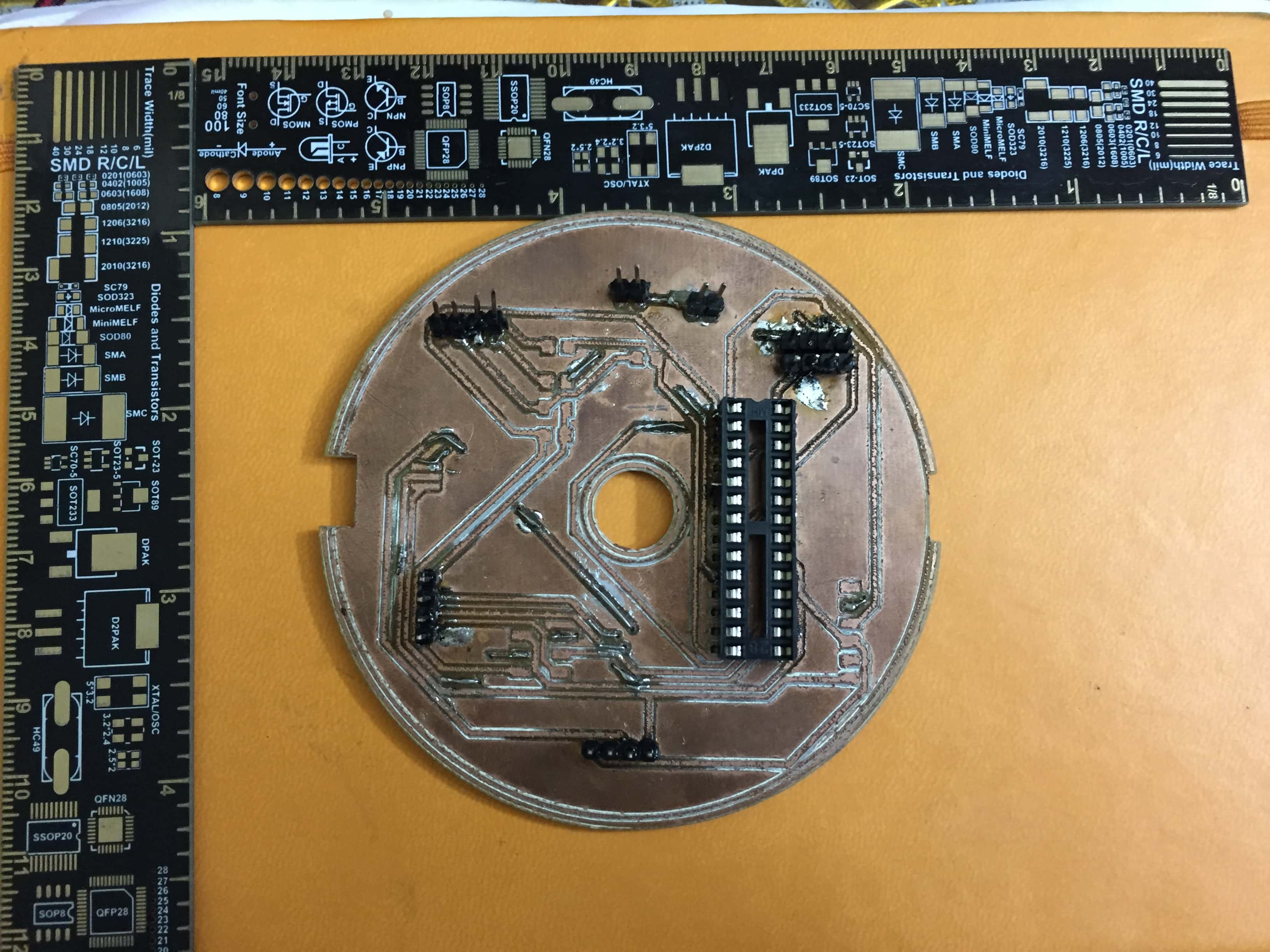
Soldering
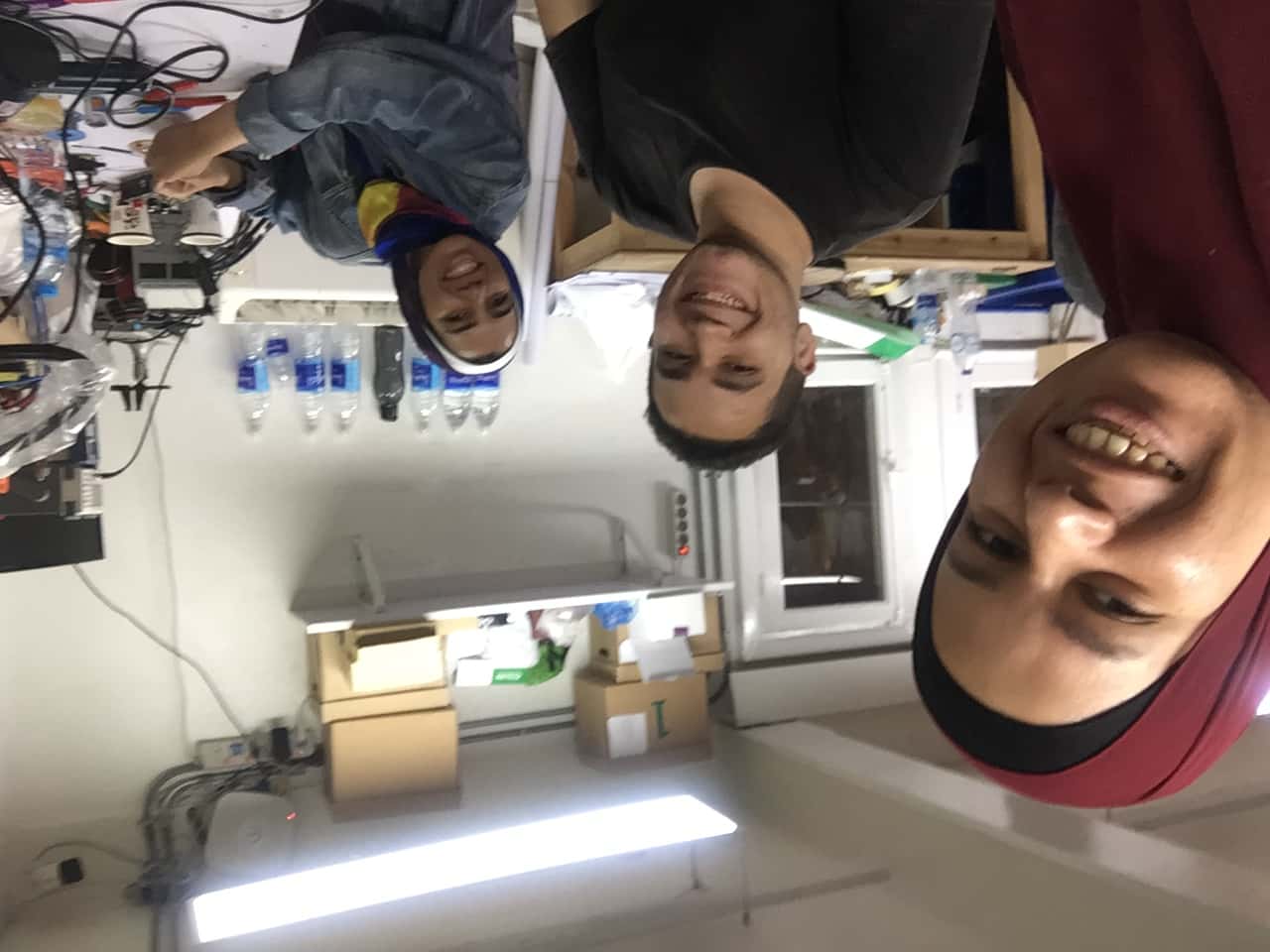
For soldering,as I was working on the PCBs of many assignments in parallel,I had a lot of soldering to do.My sister Mayar
and Mohamed El Sayed
voulenteered to help me soldering,
it was more of soldering party as even Mayar's friends wanted to help ,we spent the whole night soldering they finished
the vias.Later on I repeated this PCB many
times to fix an issue but they saved me a lot of time.Thank you so much guys.
In the picture below Mayar and Mohamed El Sayed.