Computer-Controlled Machining
Individual assignment:
Make (design+mill+assemble) something big
Group assignment:
Test runout, alignment, speeds, feeds, and toolpaths for your machine.
Intro
In this week I decided to make a design for a table that changes height .And to do so I made the base as dovetail joint. The part can have three positions.
I saw similar idea as a chair.

Design of the part 2D
I used fusion 360 in the design. I made the table with paths and grooves.
Also I made the cornrers as dog bone with a 6mm diameter :the tool size.
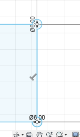
And the legs of the table as dovetail joint.


I made a parametric design.I drew the first joint then I made a patern of it.


Design of the part: 3D Model
I made a 3D model for the table :
First position:
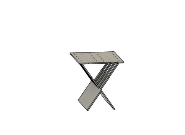
Second position:
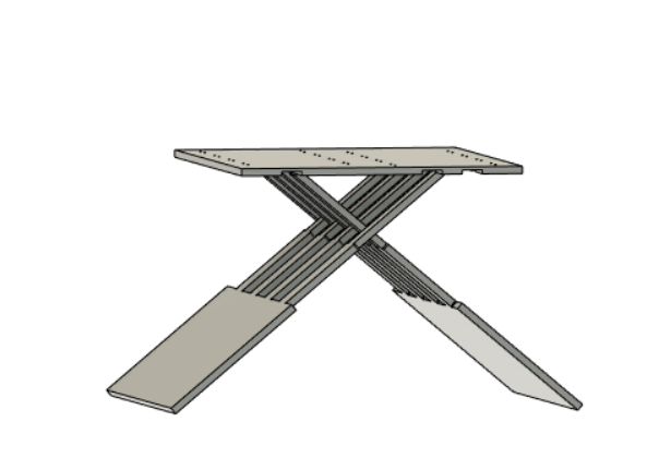
Third position:
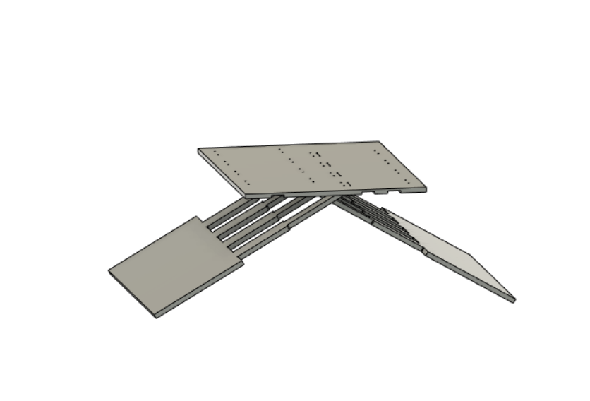
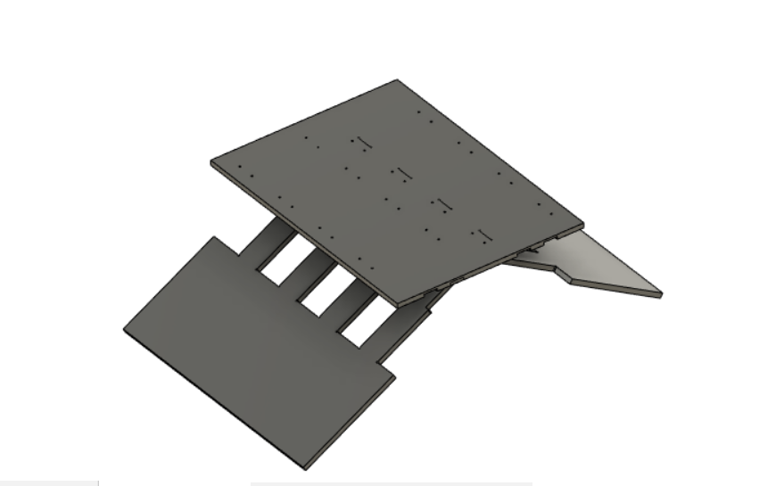
And those are the tracks engraved in the table to hold the legs:

Tool Path /Aspire
The first trial I forgot to document the steps aspire program and toolpath but I returned and redid the process to document it.Here are the steps how we prepared the part on Aspire to mill it:
We open Aspire then we open new project and we set the width height and thickness of the plywood.
Then we import the DXF file of the part then adjust the parts to fit in one sheet.
We select open vector.
We adjust the 2D profile toolpath:like the cutting depth,the size and type of the tool.In here is just a demo but all the parts were on one sheet like the previuos picture.


