Add an output device to a microcontroller board you've designed,
and program it to do something
Group assignment:
Measure the power consumption of an output device.
Brief about output devices that I used
In this week I decided to use Servo motor , stepper motor and LCD as it will be used in the final project.
Here is a brief about servo motor: A servo motor is a device that contains an encoder which converts the mechanical motion (turns of the shaft) into digital pulses interpreted by a motion controller. It also contains a driver; and in conjunction, they make up a circuit that governs the position, torque and speed
And about the stepper motor: A stepper motor, also known as step motor or stepping motor, is a brushless DC electric motor that divides a full rotation into a number of equal steps. The motor's position can then be commanded to move and hold at one of these steps without any position sensor for feedback (an open-loop controller), as long as the motor is carefully sized to the application in respect to torque and speed.
Demo/Tips and Trics
Stepper motor
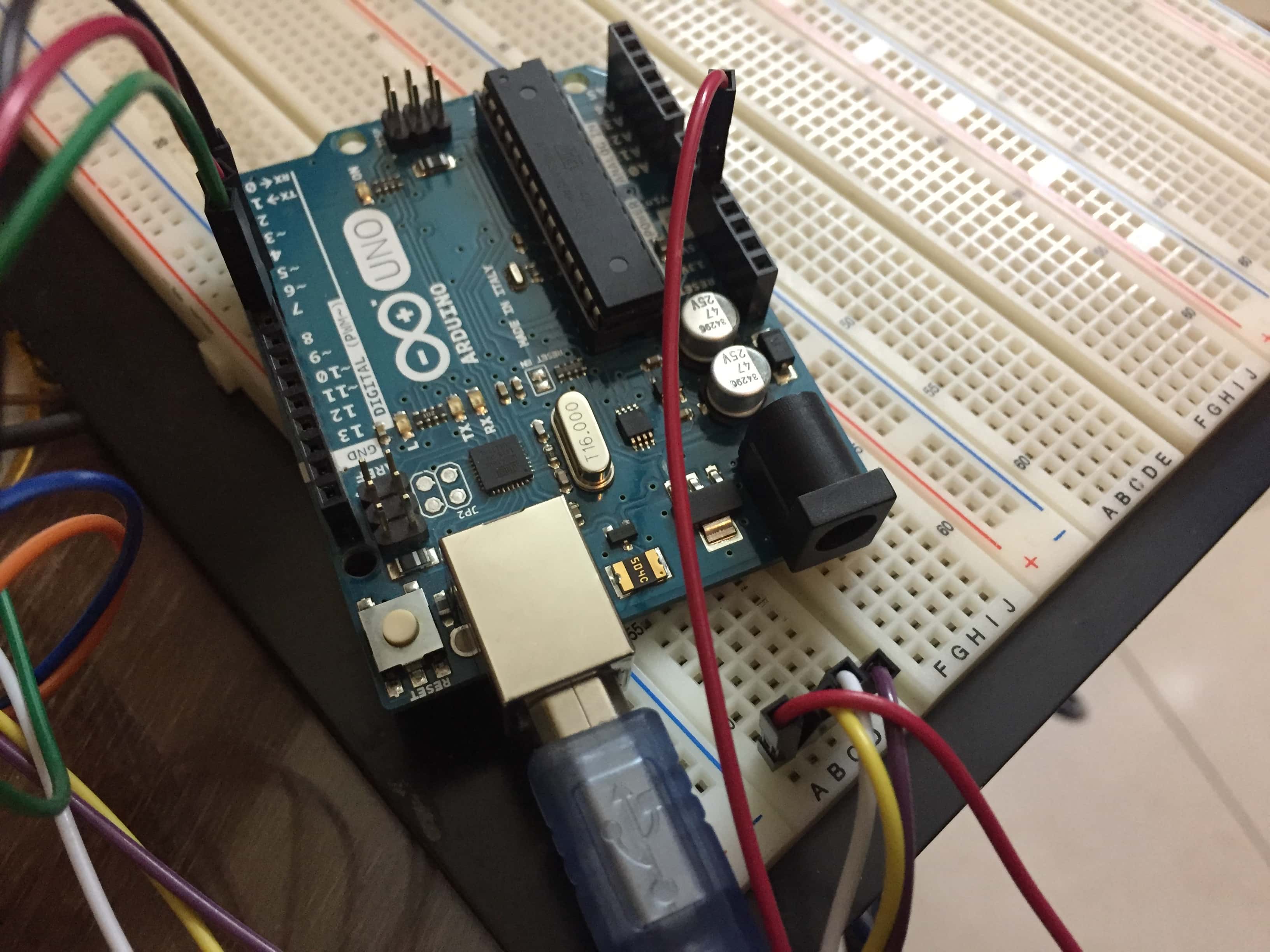
I starte to make a demo of the cicuit with Arduino UNO before working on the PCB ,just to make sure all the connections and the circuit design is correct.
Here are the components:
1)Arduino UNO
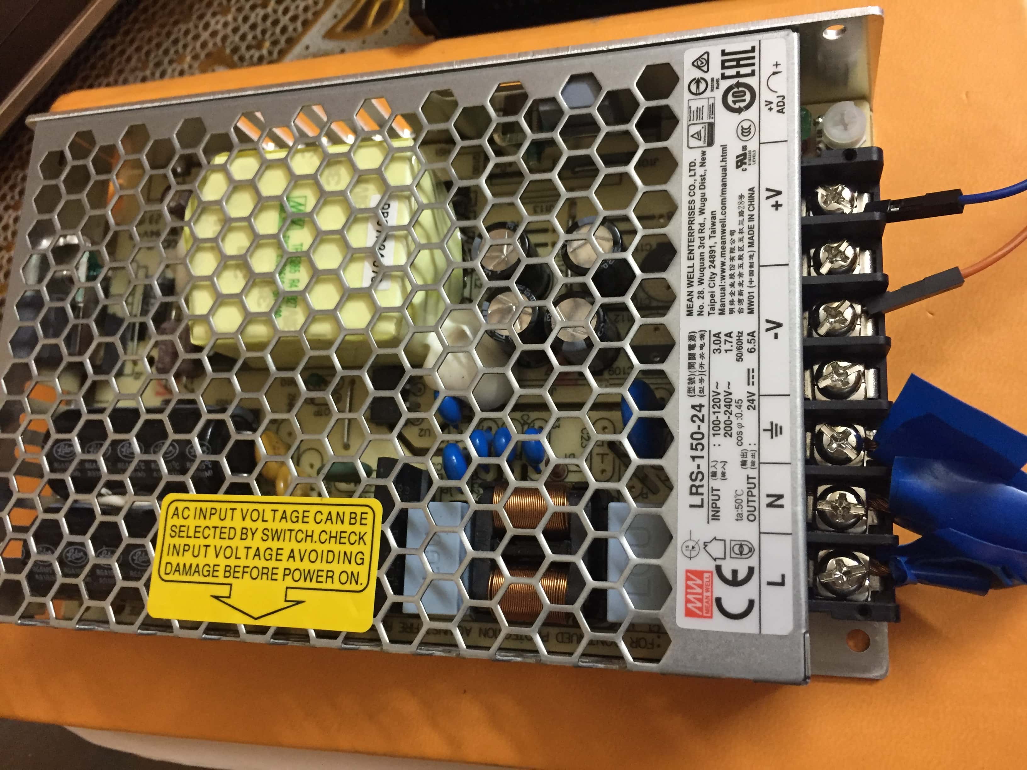
2) Power supply 24Volt
3)Driver"DM542E"
4)Bread Bord
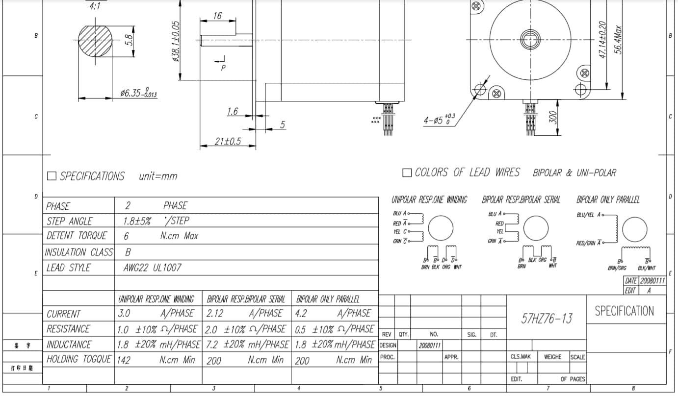
5) Stepper motor Nema 23
6)Cable
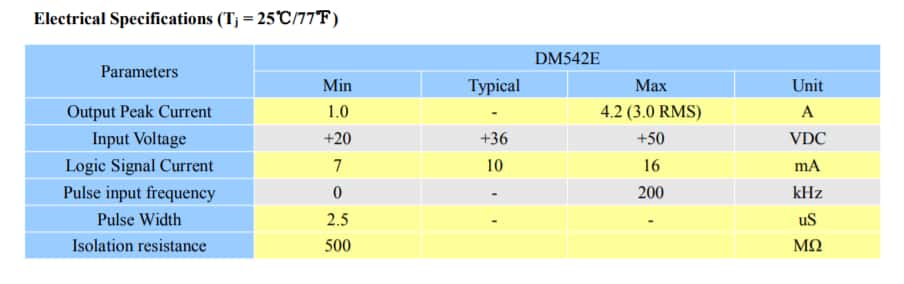
I chose this motor to be compatible with the design of the final project as it will be mentioned later in the final project page the calculations that lead me to choose this motor.As for the driver : I could have made it myself with H-bridges ,I studied and reviewd how to make it.But this motor is too powerfull for H-bridges and modules,that is why I used this driver .Here is a brief why :
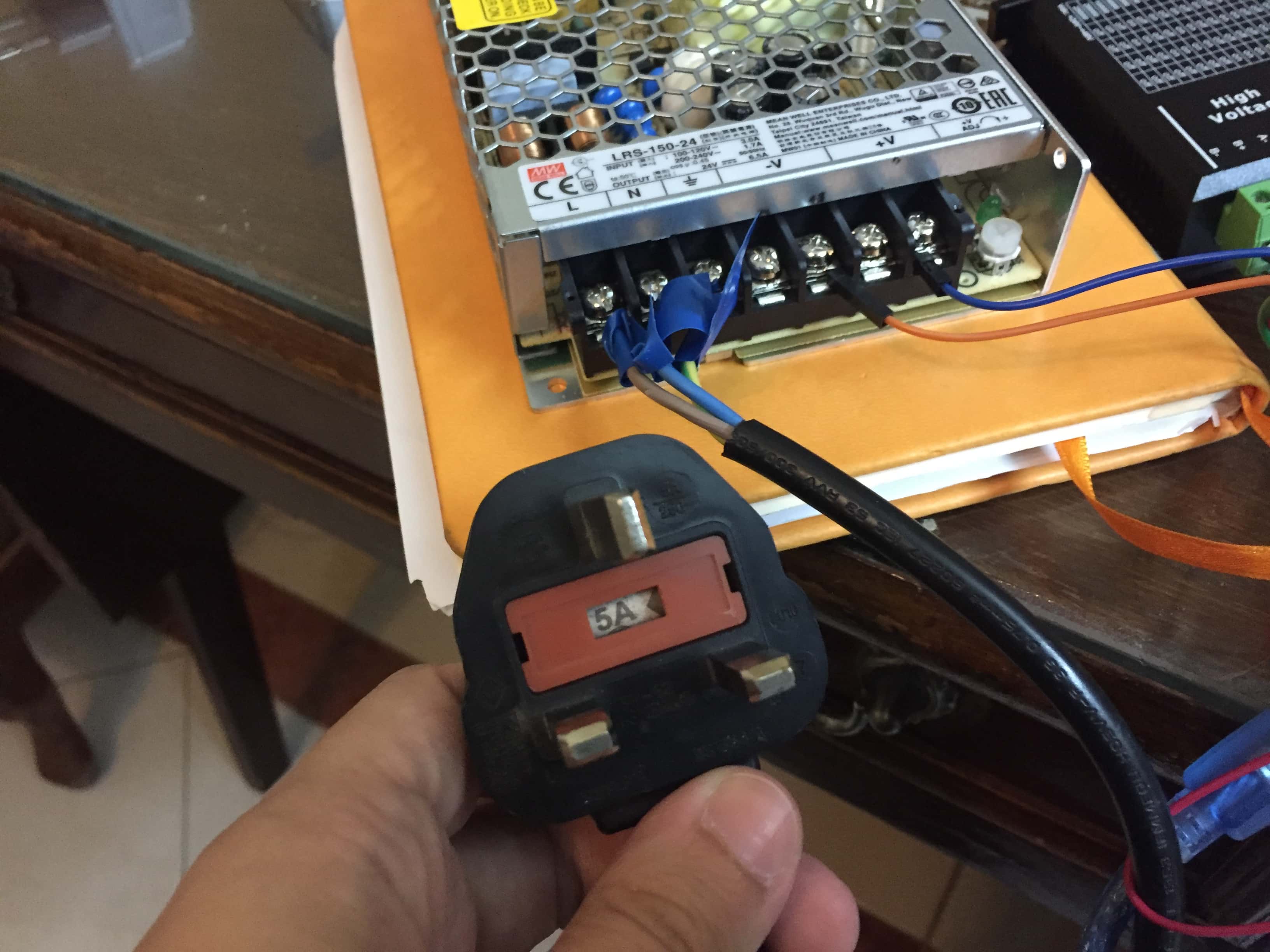
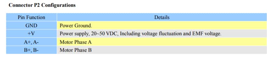
I needed the power suply to be 24V to operate the motor.
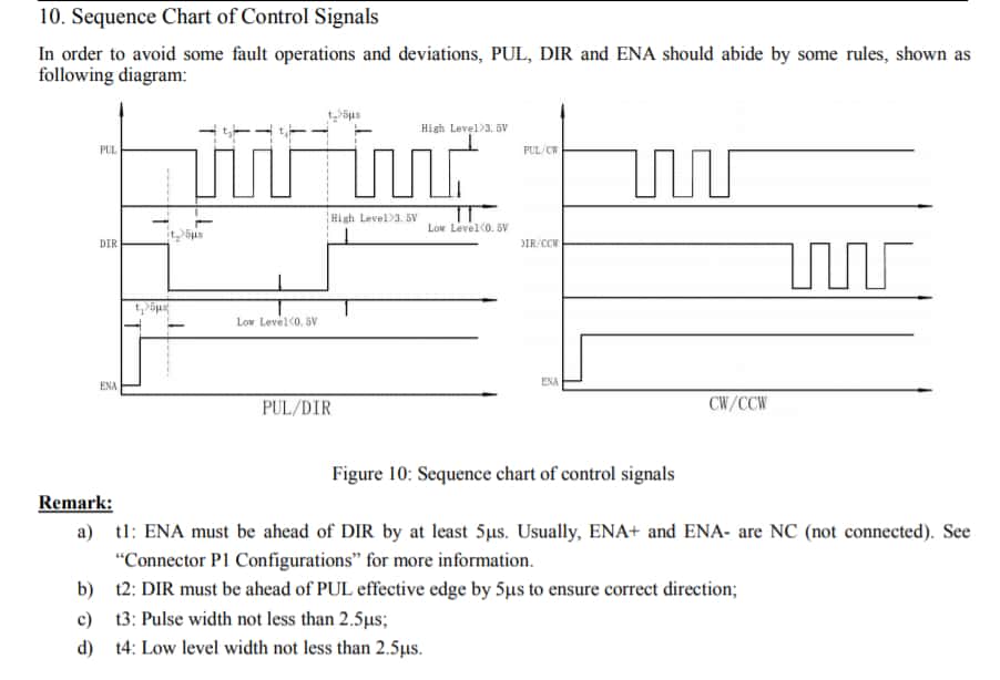
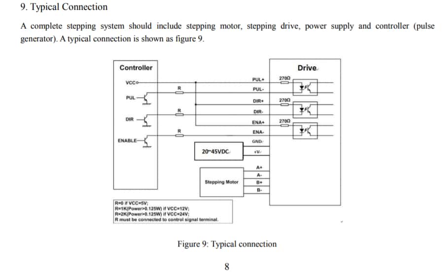
So to connect all the components together I serached in the datasheets,it's not complicated but it could be tricky.
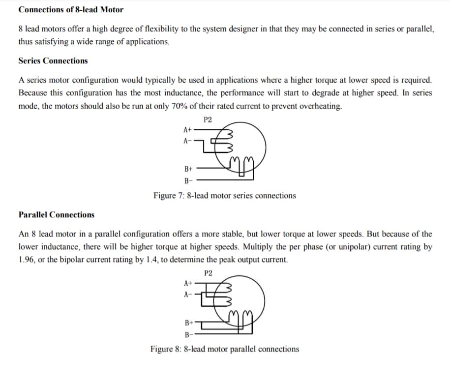
So to begin with I started connecting the motor with the driver ,I reviewd the datasheet of the motor which is bipolar with 8 leads.So the motor could be wired in series or in parallel.
Here is the explaination that I found:
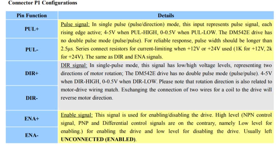
Then I proceeded by connecting the microcontroller with the driver.
I connected the power supply to VCC and ground to the driver and from the other side of the cable 220V .This cable has 3 wires .The trick here is to search for the color code to know which is L,N and ground of the cable ,but if you can't find it just use a multimeter.
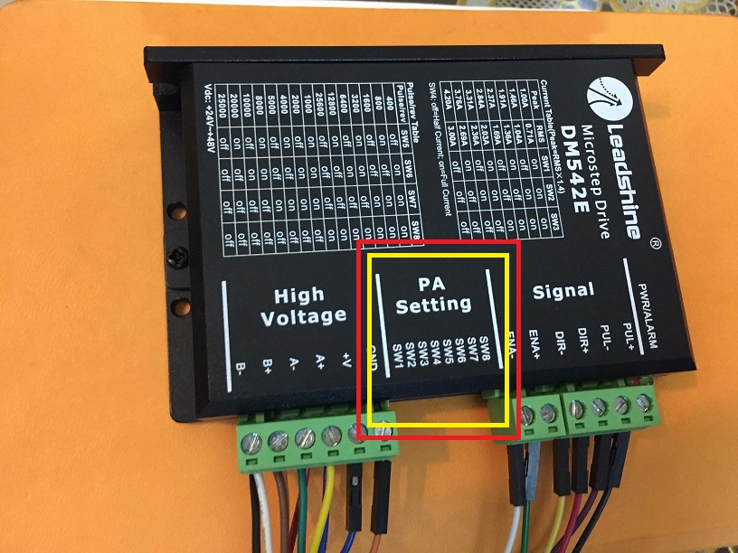
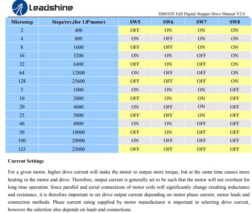
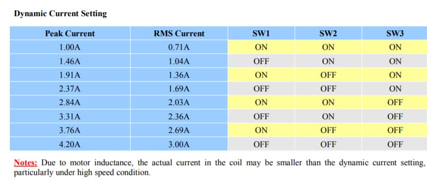
And finally:for the PA settings:
Tips and tricks:
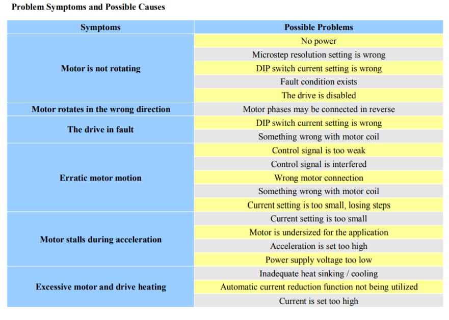
If the circuit doesn't function, here are some tips
Divide to conquer.
Test every component alone then test the connections for example :-To test the stepper motor, attache two connected leads to a led and turn the motor shaft manually if the led blinks then the motor works properly.
-To test the power supply use a multimeter and read the values.
-To test the Arduino, programe it to set some pins high and read the output with a multimeter.
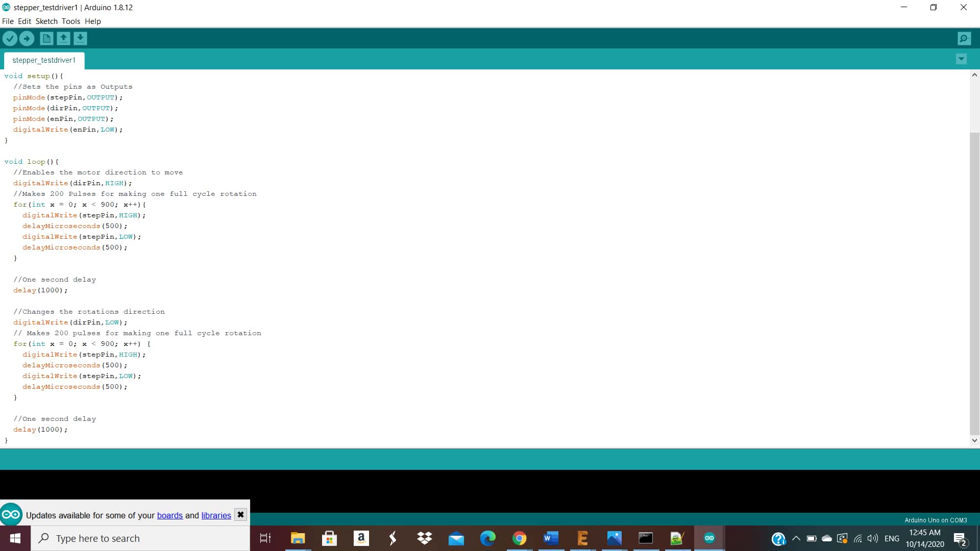
Then I programmed with Arduino UNO here is the code:
and it worked:
Design of the PCB
So now I should proceed with the PCB design.In the previous assignments I worked only on single layer SMD PCB.I was curious and I wanted to learn more on other technics to produce it.So I decided to make double layer PCB with vias .I have to thank Amani Ayman and Ahmed Ibrahim for giving me tips on how to do it.
So to design the PCB,here are the components :
-I used microcontroller Atmega 328p.
-Resonator 20 MHZ : I could have designed the PCB without it depending on the internal clock, but I wanted to make sure that all the PCB's synchronized for the upcomming assignments
-pull up resistor 10KOhm.
-1uF capacitor as a bypass.
-pins for the power supply which is 5 V.
-pins of the motor driver connected to the microcontroller.
-pins to be program the microcontroller.
-pins to communicate with SPI protocol with other boards,I will elaborate more on this subject in assignment 14.Networking and Communication.
-FTDI pins.
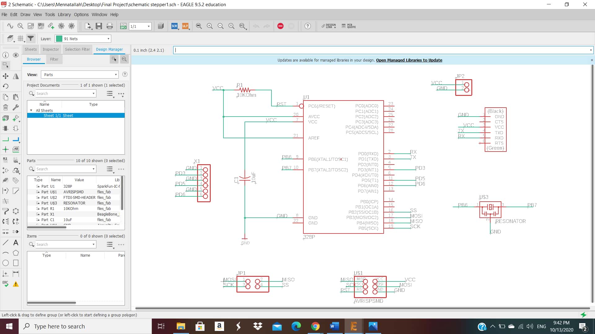
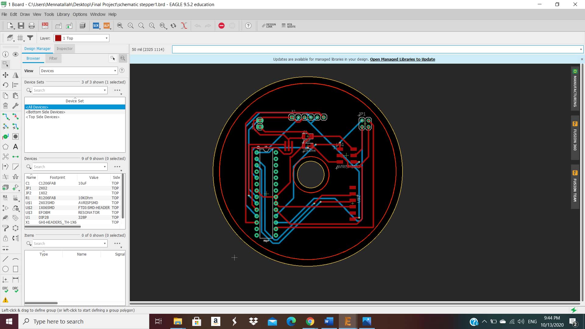
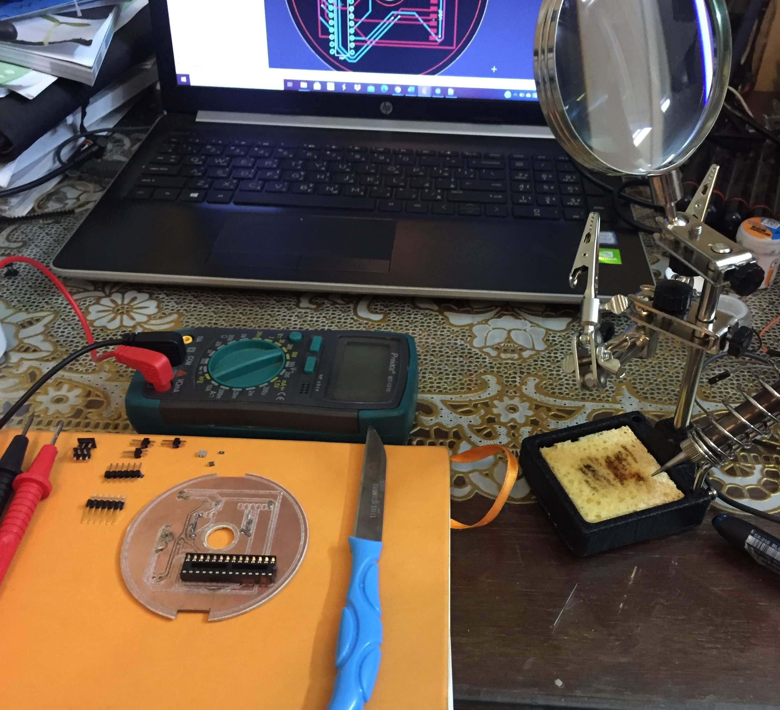
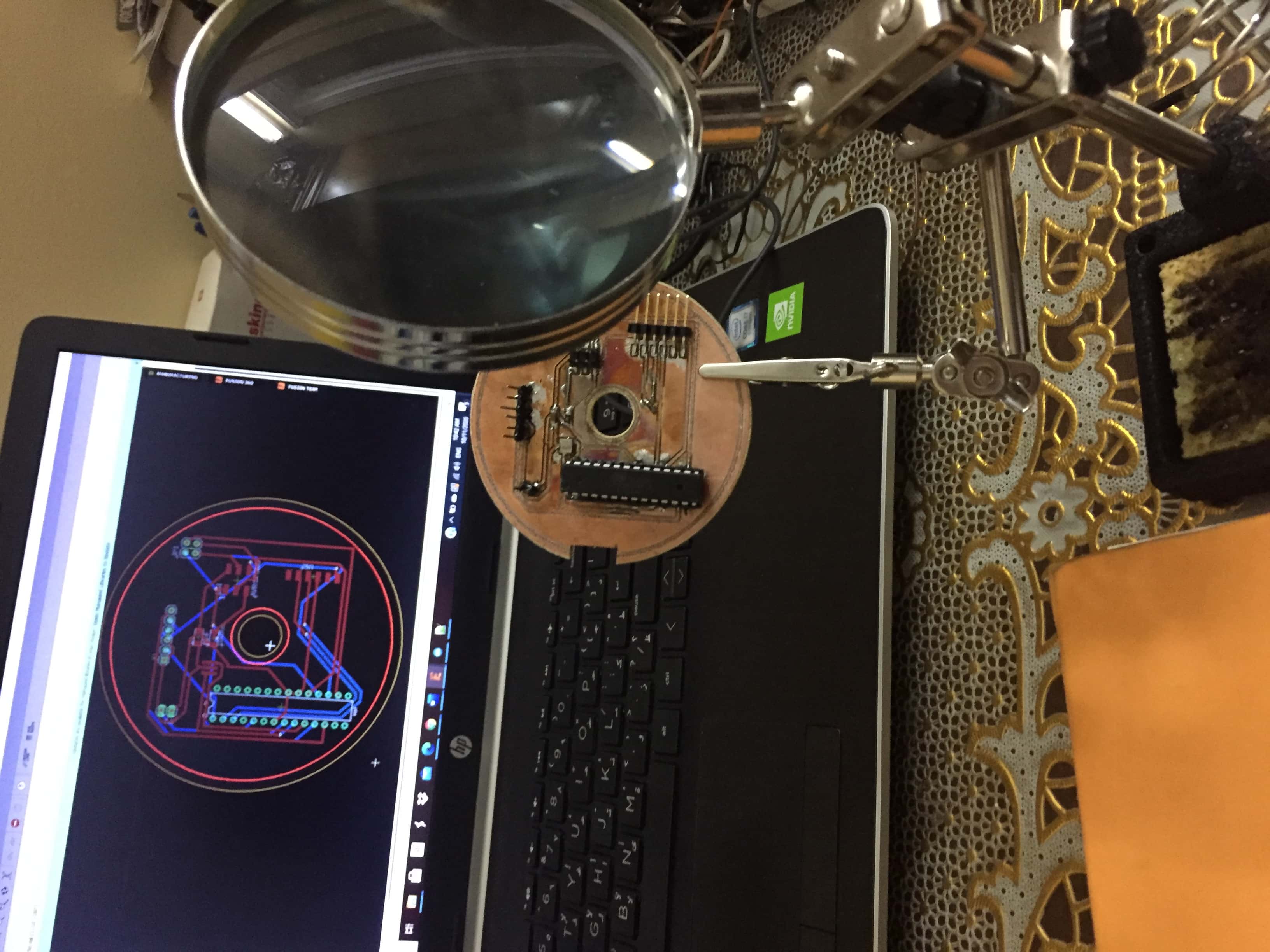
Here is the scematic design and the board layout:
Milling
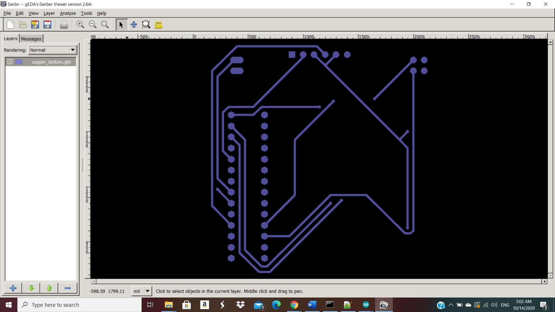
So to produce a double layer PCB with vias on Eagle ,I exported Gerber Files.
Then I downloaded Gerber viewr and I adjusted the colors of each layer.
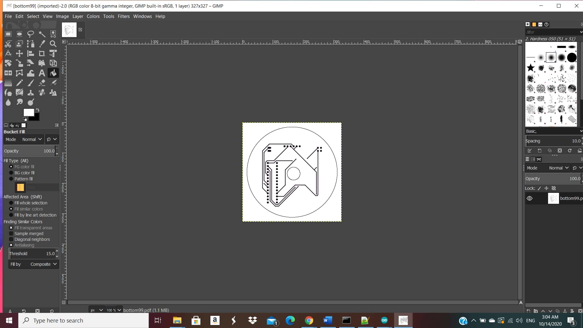
Then I exported the files as PDF.
I opened it on Gimp to turn it to PNG.
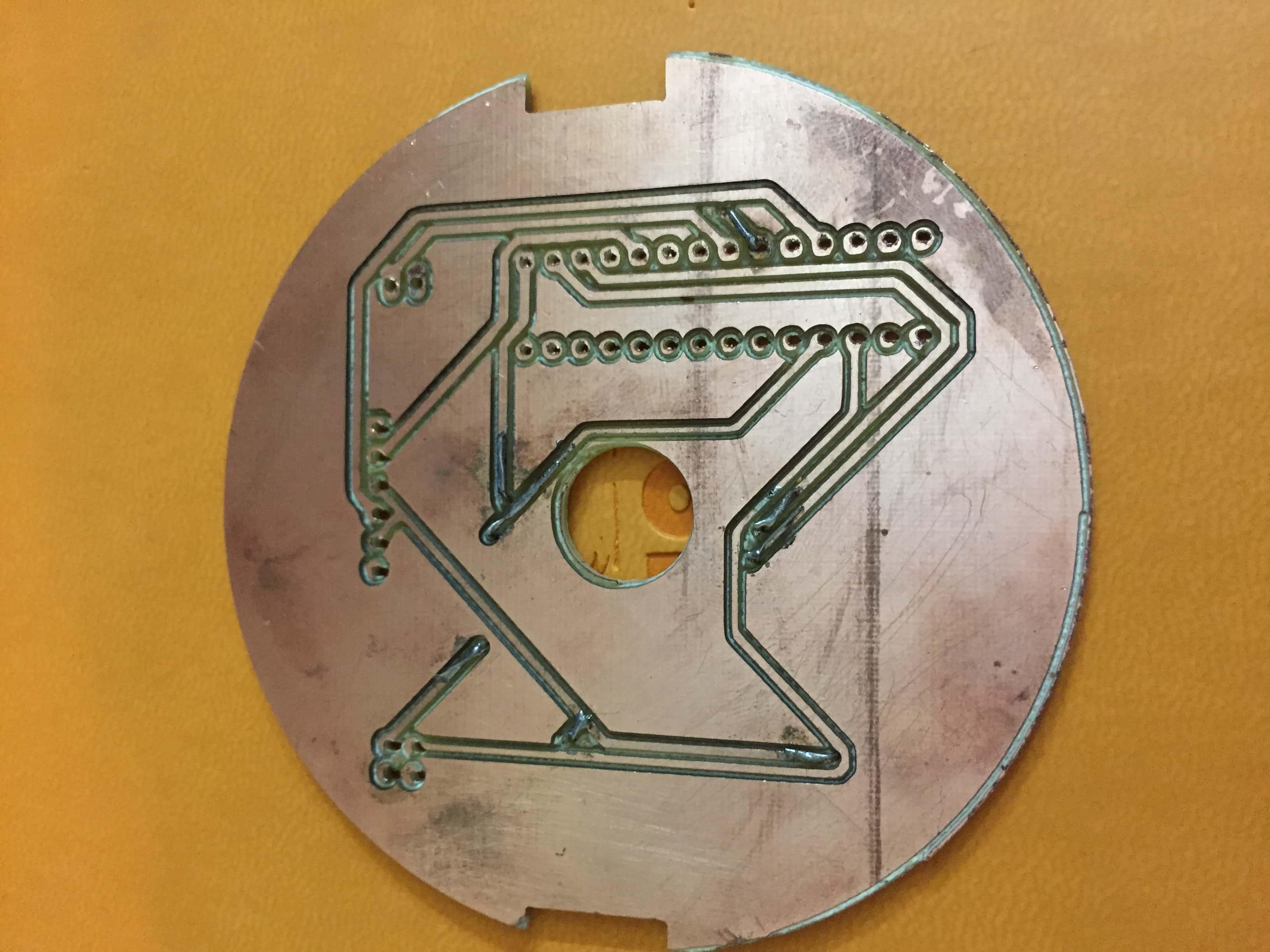
I designed the PCB rounded and with a particular design ,later I will explain why I made such design in the final project page.But for that the production of the PCB,it wasn't easy as when I turn it over to mill the bottom layer ,it was hard to align the holes ,vias and traces with the top layer.So Kidwany advised me to make a notch in the pcb to solve the dilemma.It was a brilliant idea because the PCB's came out perfect.
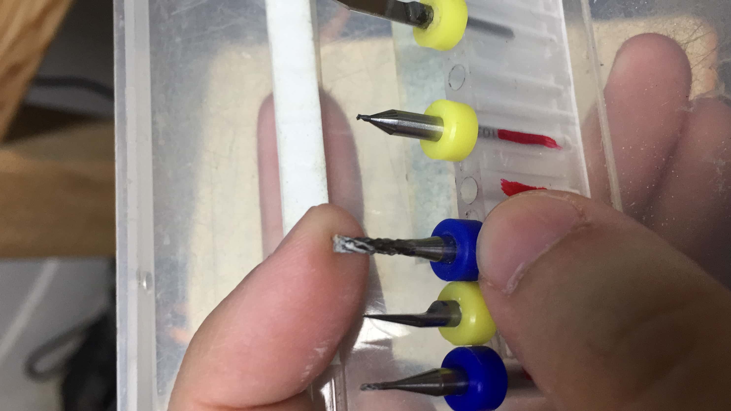
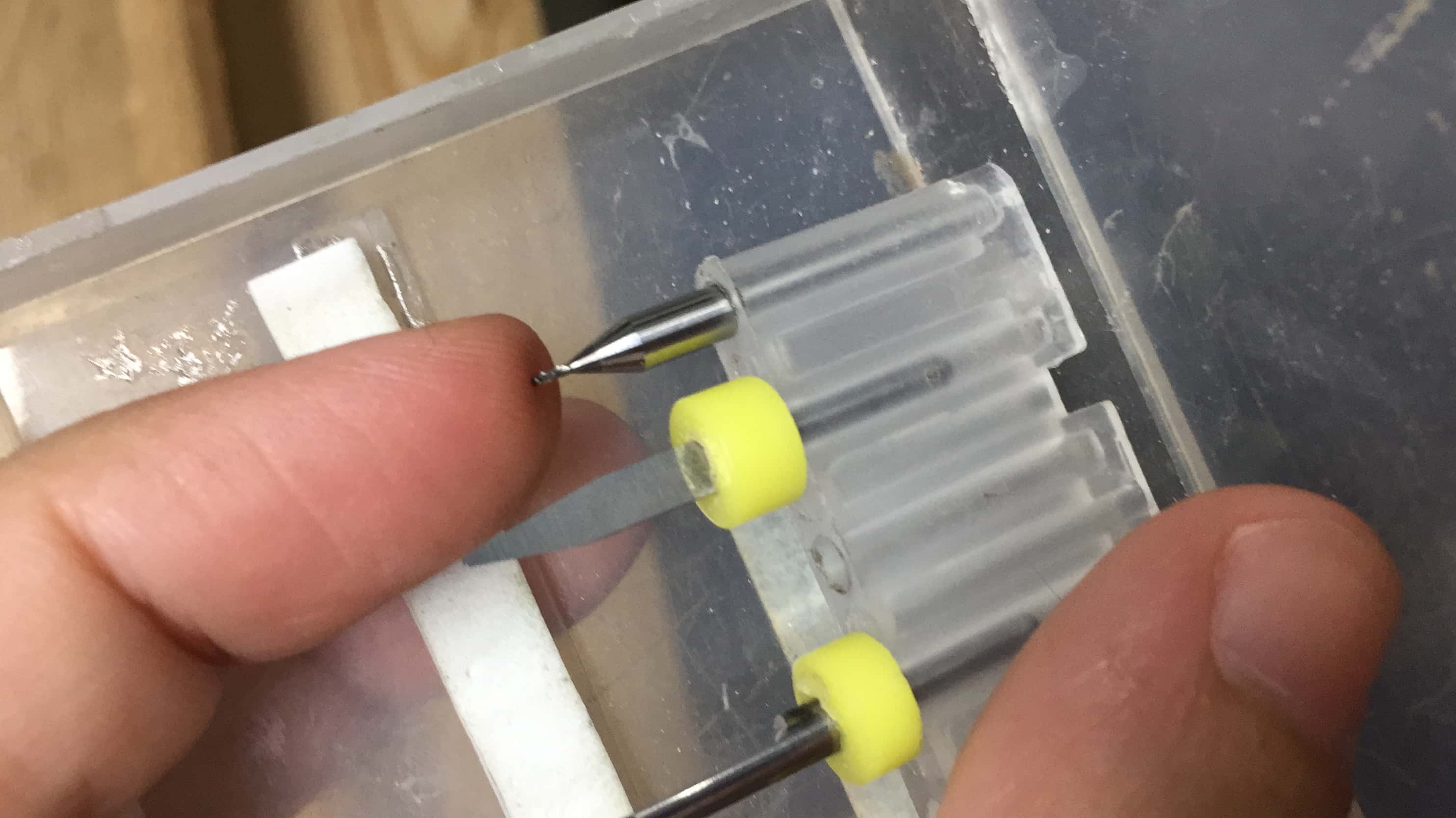
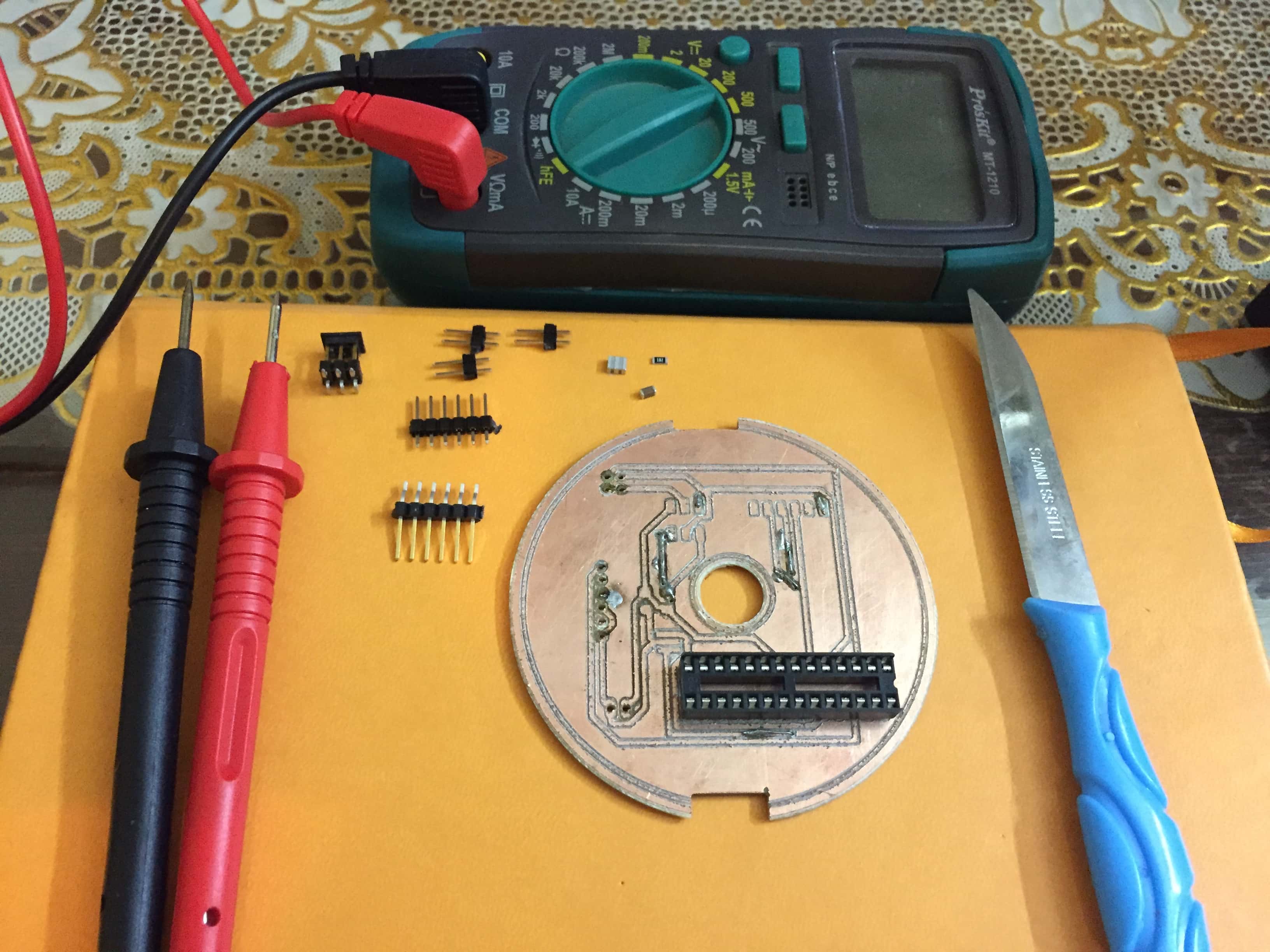
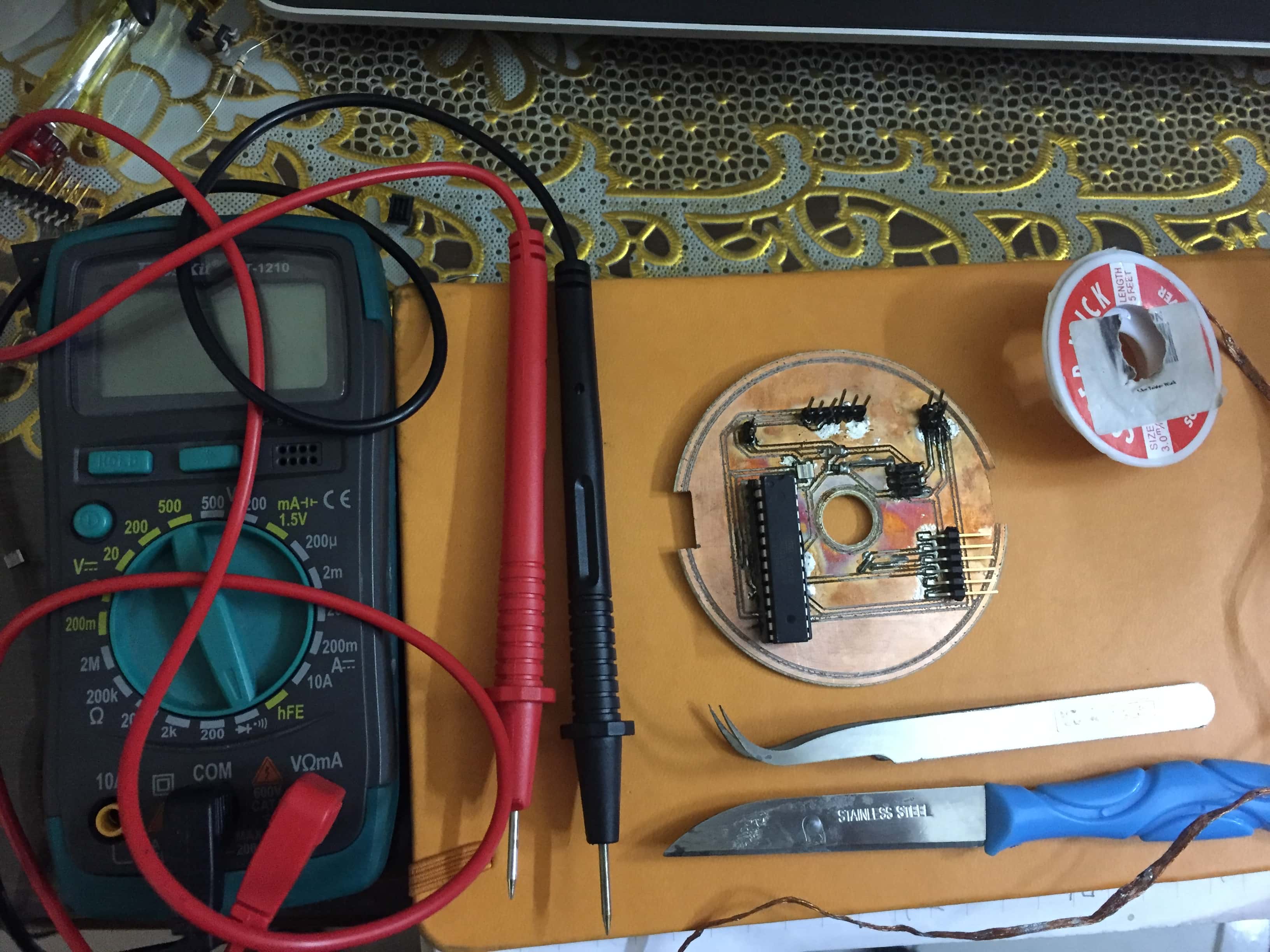
Those are some tools I used:
So the process went as the following:
1) After preparing the pcb and hold it to the millimg machine bed,I started to do the traces of the top layer with V tool 0.3mm,I had to be carefull because if the bed isn't properly levelled the tool could ruin the traces.
2) Then I changed the tool to drilling 0.6 mm ,to make the vias and the holes. Well here there is a trick which is making the tool diameter as small as possible in Fab Modules program to be able to recognize the vias in the pcb.Actually this resulted a really good outcome the holes and the Vias came out perfect.
3)I changed the tool to 1/32 to cut the outline of the PCB and I made sure that the depth is big enough to leave traces on the bed ,so that I can flip the PCB at the exact same place.
4) Before flipping the board or moving it ,I had to make the two notches on the side of the PCB to align the holes with the tracres of the bottom layer also with tool 1/32.
5)I flipped the PCB really carefully and aligned the notches,then I changed the tool to 0.3mm again to make the traces.
Finally
Soldering
So for soldering,there is a lot of tricks that I learned.
There is something which called
Soldering strategy
where I plan how to solder the PCB based on the components,which comes first,and which requires the least heat in the PCB ,Mohamed Kamel advised us in assignment4 "Electronic production" to solder from the middle out and the short components first,that was for single layer PCB.After doing a double layer , I discovred that there is a lot more to know.For example : -The PCB gets damaged with a lot of heat and it loses conductivity.
-Heating too much the oscillator and the Atmega chip ruins the components,and damage the internal clock frequency,so I should solder them at last.
-For soldering the microcontroller chip ,I noted this brillinat trick which is using a socket ,it's cheap but it saves a lot of hassel and it preseves the chip from the heat,also I can remove the chip easly and replace with another.
Soldering Process :
1)I started soldering the vias :where I used resistors' legs to connect the upper layer with the lower layer.
2)Then I did the pins and socket.
3)Finally I soldered the oscillator ,diode and resistor.
Then I tested the board connections with a multimeter.
Testing
In this section I should put the board to the test and program it.
So here is the moment of truth will the PCB work properly.
I connected the pcb to Atmel ICE and powered it with 5 V adaptor,then I openend Atmel Studio7 .
First I checked if the PCB is read to begin programming,but there was an error like the following:
So I started debuging ,I searched online ,then I checked every connection in the PCB also
I changed the Oscillator ,there was a problem with the connections of the ISP junction.So it worked:
Then I started coding the chip and I connected it to the motor driver but still it didn't work,I didn't know why so
I divided the circuit in two .
The first part is the motor and the driver and the second part is the chip and Atmel ICE. I connected
the motor to arduino and it worked just fine.For the second part the chip and Atmel ICE I connected it to a
bread board and a led ,so I programmed the chip and tested .
the sequence of operation was fine but I measured the output voltage from the pin it was 2.5 V
,and the required voltage to operate the driver is from 4 to 5 V.
So I fixed the solder and I remeasured it it gave 5 V but the first problem occured again .
So now I'm trying debuging again ,I figured the problem is with the oscillator ,I ran out of oscillators for the moment
,I should get it and proceed debuging.
I also did another output device which is LCD which will be
explained in details in the interface and the communication assignment.


 -To test the power supply use a multimeter and read the values.
-To test the Arduino, programe it to set some pins high and read the output with a multimeter.
Then I programmed with Arduino UNO here is the code:
-To test the power supply use a multimeter and read the values.
-To test the Arduino, programe it to set some pins high and read the output with a multimeter.
Then I programmed with Arduino UNO here is the code: