
Week 12 (Interface and Application Programming)
Week 12
Week 12
Node-Red is a Flow-Based programming for the internet of thing. The user can program fast just by knowing the logic and not a programing language, but by learning JavaScript the user can take full advantage of Node-Red. Node-RED was built using Node.js. I will dominate Node-Red to build my final project UI with it. I’ll do some tests to see Node-Red’s behavior and dominate it as much as I can. The installation process is really detailed in Node-Red website. The process is similar to what you would do in Linux (open task manager and us commands to install the needed programs). When you finish the installation run the command “node-red” so that your computer turns into a server and generates a local IP address so thar other devices can work in a FLOW or test the UI. I did some testing in Windows but I wouldn’t recommend relying on Windows. After a system update I had some problems executing Node-Red.
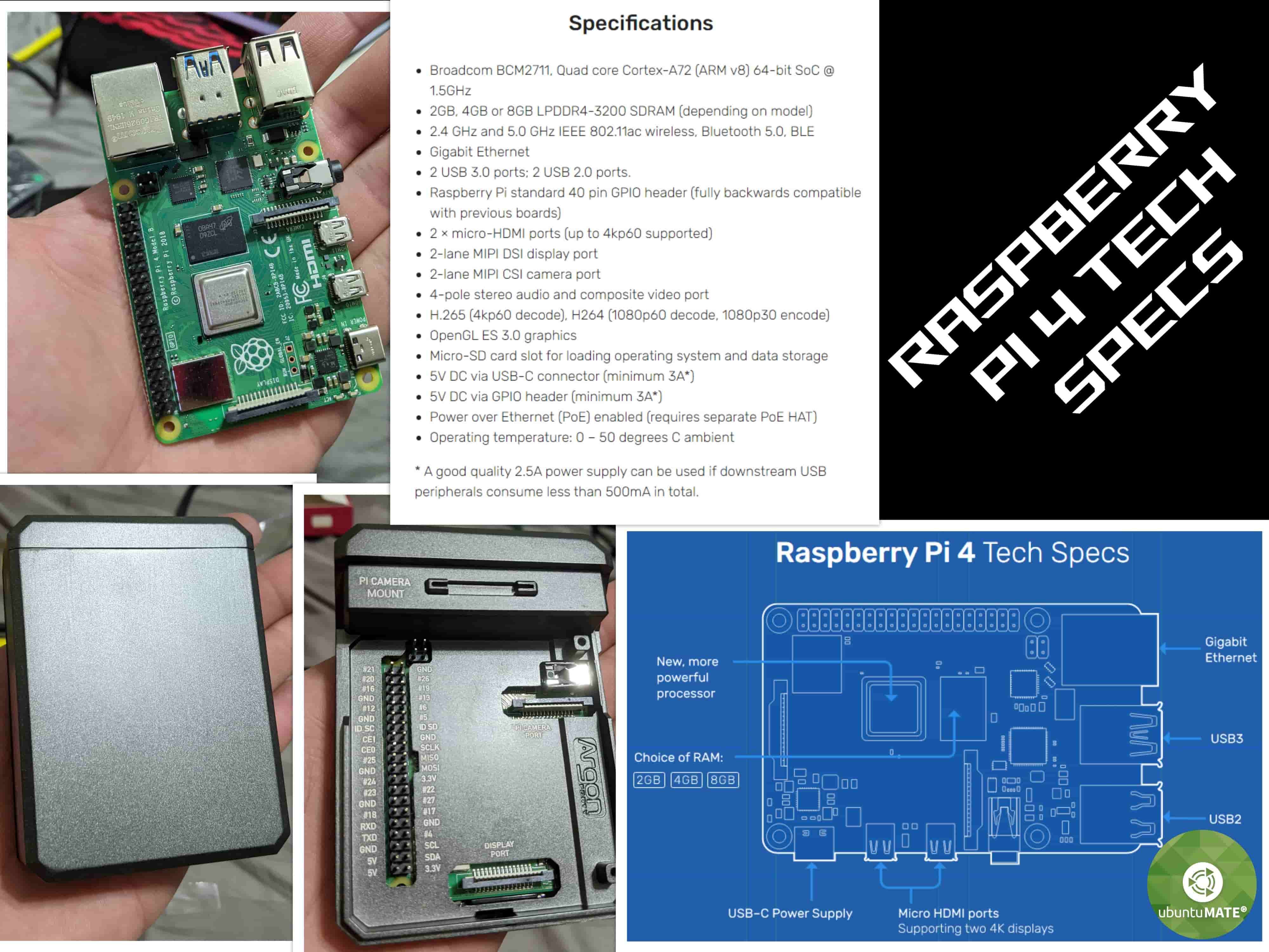
I made the decision to setup my Raspberry pi 4 with Linux (Ubuntu MATE). Then you can install every software that you want. Node-Red has a command that you can execute in the terminal. This command will do everything that’s needed to setup everything.
After getting familiar with the program I tried the “debugging” nodes and the “dashboard” nodes. Really easy to setup and play around with one input. The next step is to study how the “Function” nodes to handle more than one input (to use its maximum potential you need to have knowledge with JavaScript).
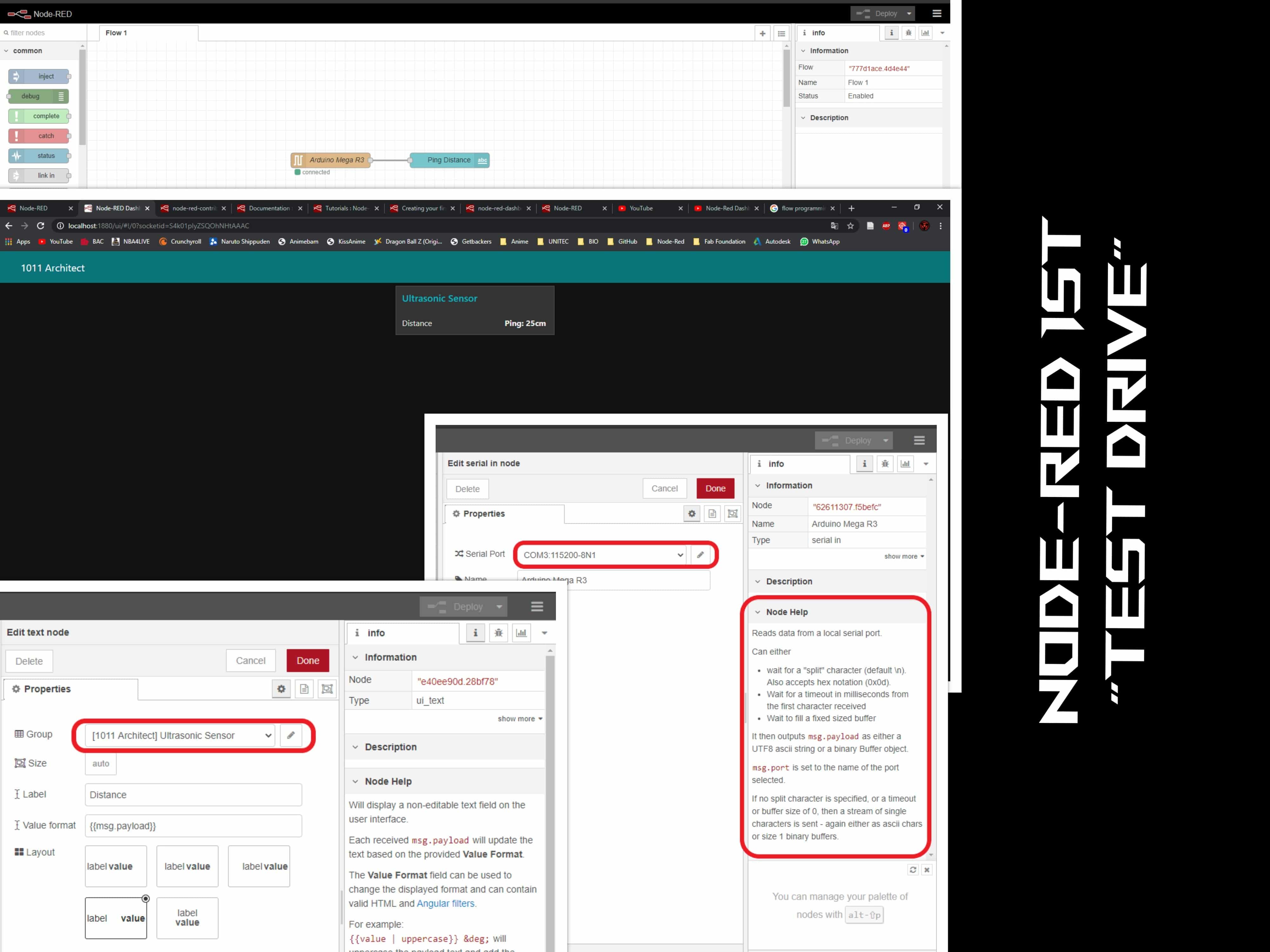
Now comes a real challenge… Enable serial communication with an MCU. To make this possible I need to sent a string that will execute an action. I needed to work simultaneously with Node-Red and the Arduino IDE to confirm if I was successfully sending the strings and receiving them but the first step was to calibrate the servos. The next code helps with this step.
            #include <Servo.h>

            Servo S_1;  // create servo object to control a servo

            void setup() {

              S_1.attach(11);  // attaches the servo on pin 9 to the servo object
            }

            void loop() {

              S_1.write(63);   // servo.write(angle)
We must include the servo.h Arduino Library. The problem that I found was that most of these libraries work with servos with an angle of rotation between 0 - 180. The once I’m using go from 0 - 270. I'm sign the DS3218MG ANNIMOS DS-Model Servo. Something happened with the official website but I have access to the data sheet.
              #include <Servo.h>

              Servo S_1;  // create servo object to control a servo
              Servo S_2;
              Servo S_3;


              char Accessories =0;


              void setup() {
                Serial.begin(9600);

                S_1.attach(11);
                  S_1.write(0);
              //      delay(1000);


                S_2.attach(10);
                  S_2.write(0);
              //      delay(1000);


                S_3.attach(9);
                  S_3.write(0);
              //      delay(1000);


              }

              void loop() {

                if (Serial.available() > 0) {
                  Accessories = Serial.read();
              switch (Accessories) {
                  case '1':
                    S_1.write(63);
                     break;

                  case '2':
                    S_2.write(59);
                     break;

                  case 'C':
                    S_3.write(65);
                     break;

                  case '8':
                    S_1.write(0);
                    S_2.write(0);
                    S_3.write(0);
                     break;             }


                }
              }
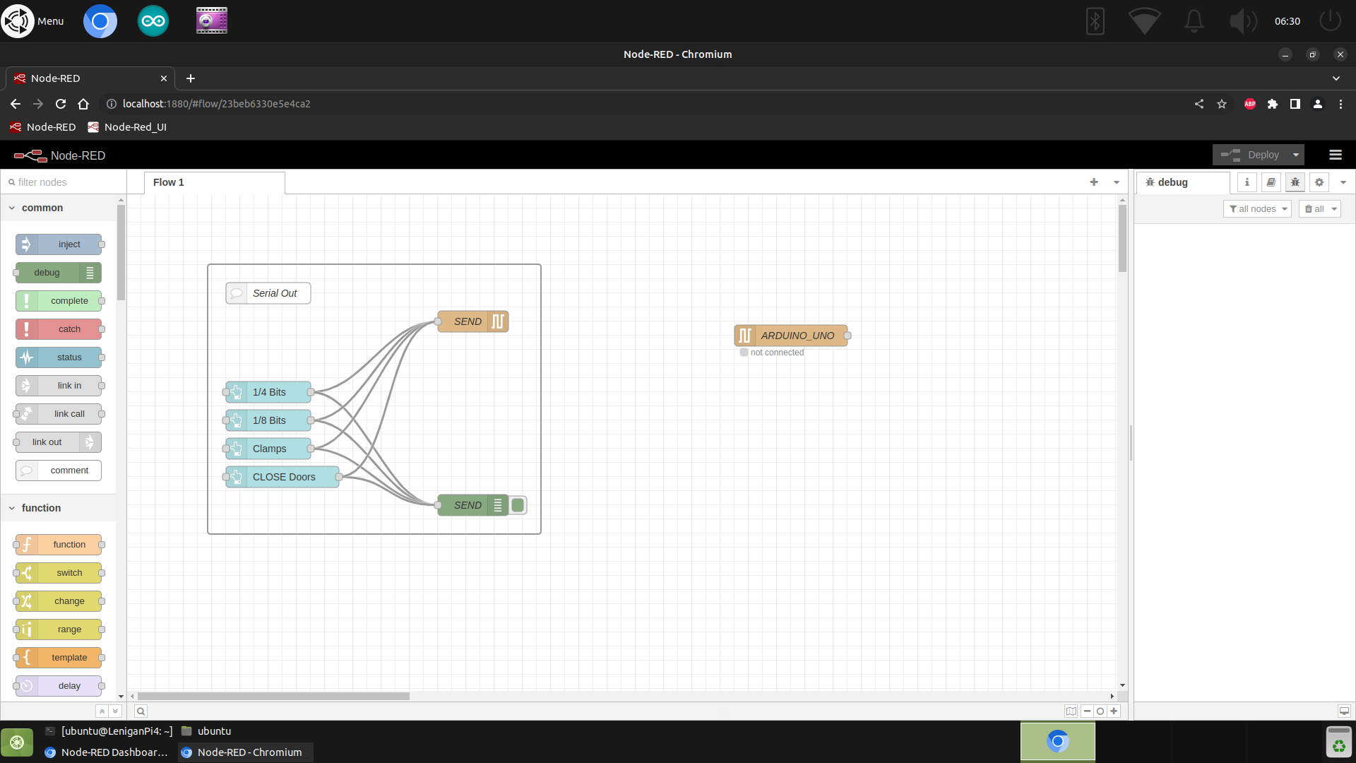
While Node-RED was an excellent tool for the initial "Discovery Phase" to prototype the logic and visualize the User Interface (UI), it was not suitable for the final standalone product for two main reasons:
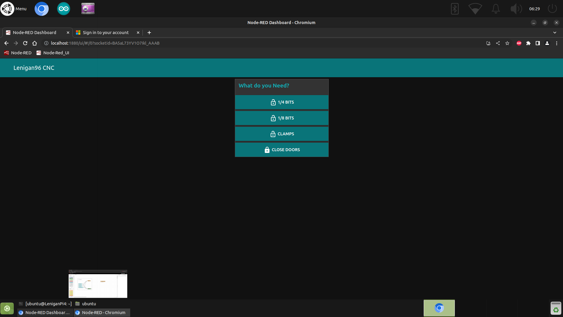
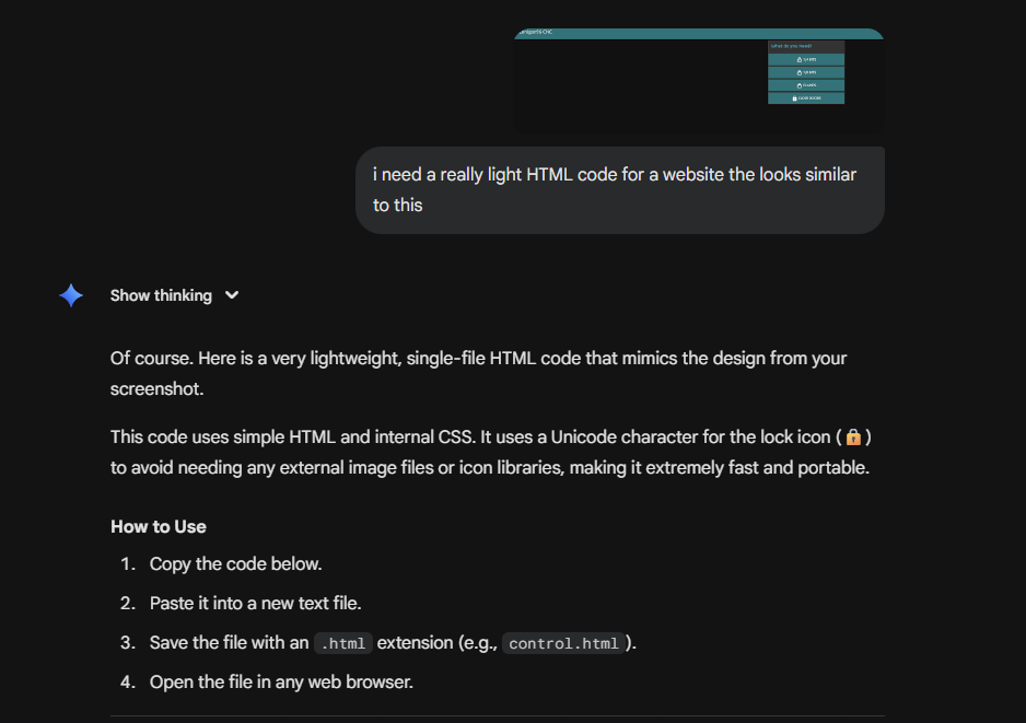
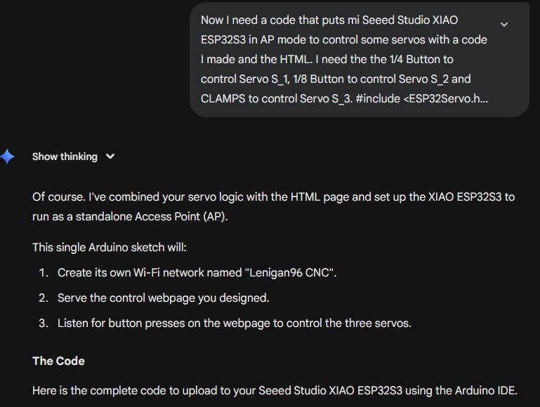
The Solution: To achieve a truly wireless and standalone device, I moved the logic from the external Node-RED server directly onto the microcontroller. I used Gemini 2.5 Pro to help generate C++ code that embedded the HTML and CSS web interface directly into the ESP32's firmware. This allows the box to host its own website and control the servos without needing Node-RED or an internet router. I took a screen shot of the HTML5 I created with NODE RED and generated a code that looked similar with the help of Gemini.
The code I made is in WEEK 4.
#include
#include
#include
// --- Wi-Fi Access Point Settings ---
const char *ssid = "Lenigan96 CNC"; // The name of the Wi-Fi network to create
const char *password = "cnccontrol"; // The password for the Wi-Fi network. Use NULL for an open network.
// --- Web Server Initialization ---
WebServer server(80); // Create a web server on port 80
// --- Servo Initialization ---
Servo S_1; // Servo for "1/4 BITS"
Servo S_2; // Servo for "1/8 BITS"
Servo S_3; // Servo for "CLAMPS"
// Define the GPIO pins for the servos
const int SERVO_1_PIN = 1;
const int SERVO_2_PIN = 2;
const int SERVO_3_PIN = 3;
// --- Physical Button Initialization ---
const int BUTTON_S1_PIN = 8; // Physical button for Servo 1
const int BUTTON_S3_PIN = 7; // Physical button for Servo 3
const int BUTTON_RESET_PIN = 44; // Physical button to reset all servos
// --- HTML Webpage with CSS and JavaScript ---
const char webpage[] PROGMEM = R"rawliteral(
CNC Control
Lenigan96 CNC
What do you Need?
)rawliteral";
// --- Web Server Page Handlers ---
void handleRoot() {
server.send(200, "text/html", webpage);
}
void handleServo1() {
S_1.write(63);
Serial.println("Servo 1 (1/4 BITS) activated via Web.");
server.send(204); // Send "204 No Content" to stay on the same page
}
void handleServo2() {
S_2.write(59);
Serial.println("Servo 2 (1/8 BITS) activated via Web.");
server.send(204);
}
void handleServo3() {
S_3.write(65);
Serial.println("Servo 3 (CLAMPS) activated via Web.");
server.send(204);
}
void handleClose() {
S_1.write(0);
delay(200);
S_2.write(0);
delay(200);
S_3.write(0);
Serial.println("All servos closed/reset via Web.");
server.send(204);
}
void handleNotFound() {
server.send(404, "text/plain", "404: Not found");
}
// --- Physical Button Logic ---
void checkPhysicalButtons() {
if (digitalRead(BUTTON_S1_PIN) == HIGH) {
S_1.write(63);
Serial.println("Servo 1 activated via physical button.");
delay(250); // Debounce delay
}
if (digitalRead(BUTTON_S3_PIN) == HIGH) {
S_3.write(65);
Serial.println("Servo 3 activated via physical button.");
delay(250); // Debounce delay
}
if (digitalRead(BUTTON_RESET_PIN) == HIGH) {
S_1.write(0);
delay(500);
S_2.write(0);
delay(500);
S_3.write(0);
Serial.println("All servos reset via physical button.");
delay(250); // Debounce delay
}
}
// --- Main Setup ---
void setup() {
Serial.begin(115200);
delay(1000);
// --- Setup Servos ---
S_1.attach(SERVO_1_PIN);
S_2.attach(SERVO_2_PIN);
S_3.attach(SERVO_3_PIN);
S_1.write(0);
S_2.write(0);
S_3.write(0);
Serial.println("Servos initialized.");
// --- Setup Physical Buttons ---
pinMode(BUTTON_S1_PIN, INPUT);
pinMode(BUTTON_S3_PIN, INPUT);
pinMode(BUTTON_RESET_PIN, INPUT);
Serial.println("Physical buttons initialized.");
// --- Setup Wi-Fi Access Point ---
Serial.print("Setting up AP: ");
Serial.println(ssid);
WiFi.softAP(ssid, password);
Serial.print("AP IP address: ");
Serial.println(WiFi.softAPIP());
// --- Define Server Routes ---
server.on("/", HTTP_GET, handleRoot);
server.on("/s1", HTTP_GET, handleServo1);
server.on("/s2", HTTP_GET, handleServo2);
server.on("/s3", HTTP_GET, handleServo3);
server.on("/close", HTTP_GET, handleClose);
server.onNotFound(handleNotFound);
// Start the server
server.begin();
Serial.println("HTTP server started");
}
// --- Main Loop ---
void loop() {
server.handleClient(); // Handle incoming web requests
checkPhysicalButtons(); // Check for physical button presses
}