Week 09
Input Devices
01
Assignments
- Group assignment.
- Probe an input device(s)'s analog and digital signals.
- Document your work (in a group or individually).
- Individual assignments
- Measure something: add a sensor to a microcontroller board that you have designed and read it.
Software
Download File
02
Assignments
Group Assignments (1)
-
Probe an input device(s)'s analog and digital signals.
Document your work (in a group or individually).
We received the theoretical explanation of this week via video conference using TinkerCAD simulating an alternative of group work, however, we have not progressed in this task.
We have not yet been able to access the FabLab, nor the corresponding equipment to carry out the physical practices, which in my case are very necessary since it is not the same as simulating situations with characteristics given by default.
We have not yet been able to access the FabLab, nor the corresponding equipment to carry out the physical practices, which in my case are very necessary since it is not the same as simulating situations with characteristics given by default.
Individual Assignments (2)
Measure something: add a sensor to a microcontroller board that you have designed and read it.
To familiarize yourself with the development of this week's assignments, please refer to Week 4 (Electronics Production) and Week 6 (Electronics Design).
Possibly this is one of the more complicated weeks, since the whole electronics part definitely hadn't been my thing until this couple of weeks. Despite working with 2 pcb and its architecture, I am still in the way of discovering how things work.
I have seen many pcbs with the ATtiny 44 format and for the components that were in our FabLab, I went for the ATtiny 45, which is also very similar to the ATtiny 85.
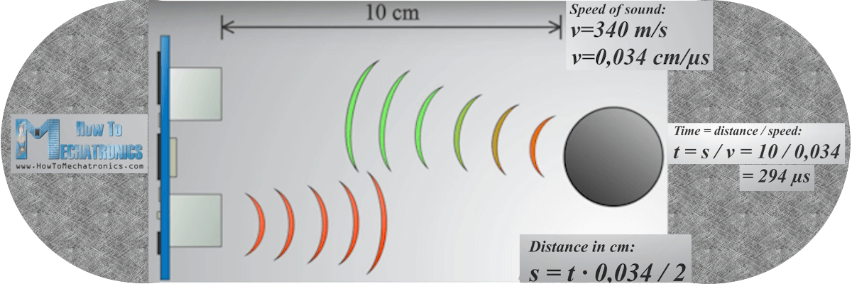
For this week, add a last ultrasonic sensor to the pcb made in week 6 (Electronic Design) and collect the information to interact with this component.
This should allow me to add an extra component that I have not tried yet and start to understand how this device works through programming and reading its information.

- Operating Voltage: 5V DC
- Quiescent current: <2mA
- Working current: 15mA
- Measurement range: 2cm to 450cm
- Accuracy: + - 3mm
- Opening angle: 15 °
- Ultrasound frequency: 40KHz
- Minimum TRIG trigger pulse duration (TTL level): 10 μS
- Output ECO pulse duration (TTL level): 100-25000 μS
- Dimensions: 45mm x 20mm x 15mm
- Minimum waiting time between one measurement and the start of another 20ms (recommended 50ms)
Connection:
- VCC (+ 5V DC)
- TRIG (Ultrasound Shot, can be)
- ECHO (Ultrasound reception)
- GND (0V)

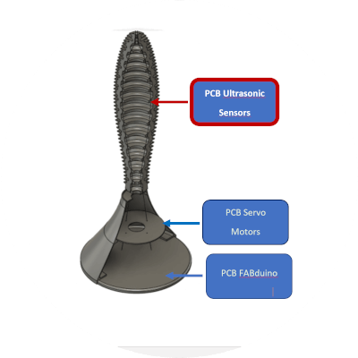
In truth, this is becoming more and more interesting and complex, in order to make the final project more practical and safe, the decision was made to create a shield to serve as a floating base, separate from the Fabduino, due to the fact of the prototype and for reasons of maintenance, repair, assembly and observation of operation; the arrangement of this is much easier.
Based on the above and describing this section of the final project, it will have a PCB at a high level and will contain the 4 ultrasonic sensors with their respective female and male adaptation jumpers.
For this assignment we use some things that are in an Arduino kit to simulate what in theory I should develop and present this week, I used this material that was provided by the instructor a few days ago, trying to advance and understand how it should work in reality, since access to the Fab is restricted by the national quarantine.
I will do it using Arduino Uno as a platform to simulate the connections of the component with the own pcb due to the lack of access to the FabLab and to be able to manufacture the pcb that I have designed in previous weeks.
For the video, change the code a little, referring to some references.
When trying to follow the steps explained virtually, in principle I spent a good couple of hours, because even modifying the steps, the schematic seemed complete, but the board was incomplete and undefined; until at last the light bulb (brain) came on and I started looking for how to read several ultrasonic sensors at the same time and it turns out that I found an interesting video that was not exactly what I originally wanted, but half a video I understood that the TRIG signal is common to all sensors, so it would save me 3 pins from the FABduino.

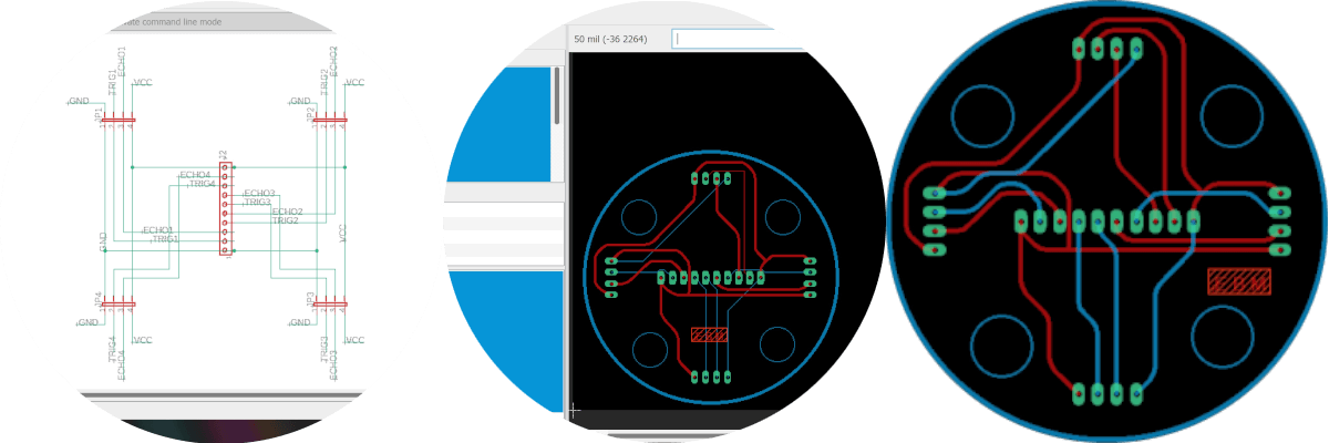
This discovery was fantastic, since it not only made me use a connector from 10 outputs to only 5, however, it was explained to me that this method is to place them in parallel, which could cause me problems when programming the final project code; but I could make the connections without problems and to make sure of that, I was designing in the schematic and seeing the result on the board. At the end of this exercise, I loved the product.

As soon as it is reliable and safe, depending on what the authorities of the Ministry of Health say; It is in the capacity to manufacture these elements and physically fulfill the assignments.

Inconveniences - Delays
- We continue with the quarantine by COVID-19