This page presents the assignments for week 9 of Fab Academy 2020: “Input Devices”.
To do list:
Group
- probe an input device's analog levels and digital signals
- measure something: add a sensor to a microcontroller board that you have designed and read it
Week 9 CAD files:
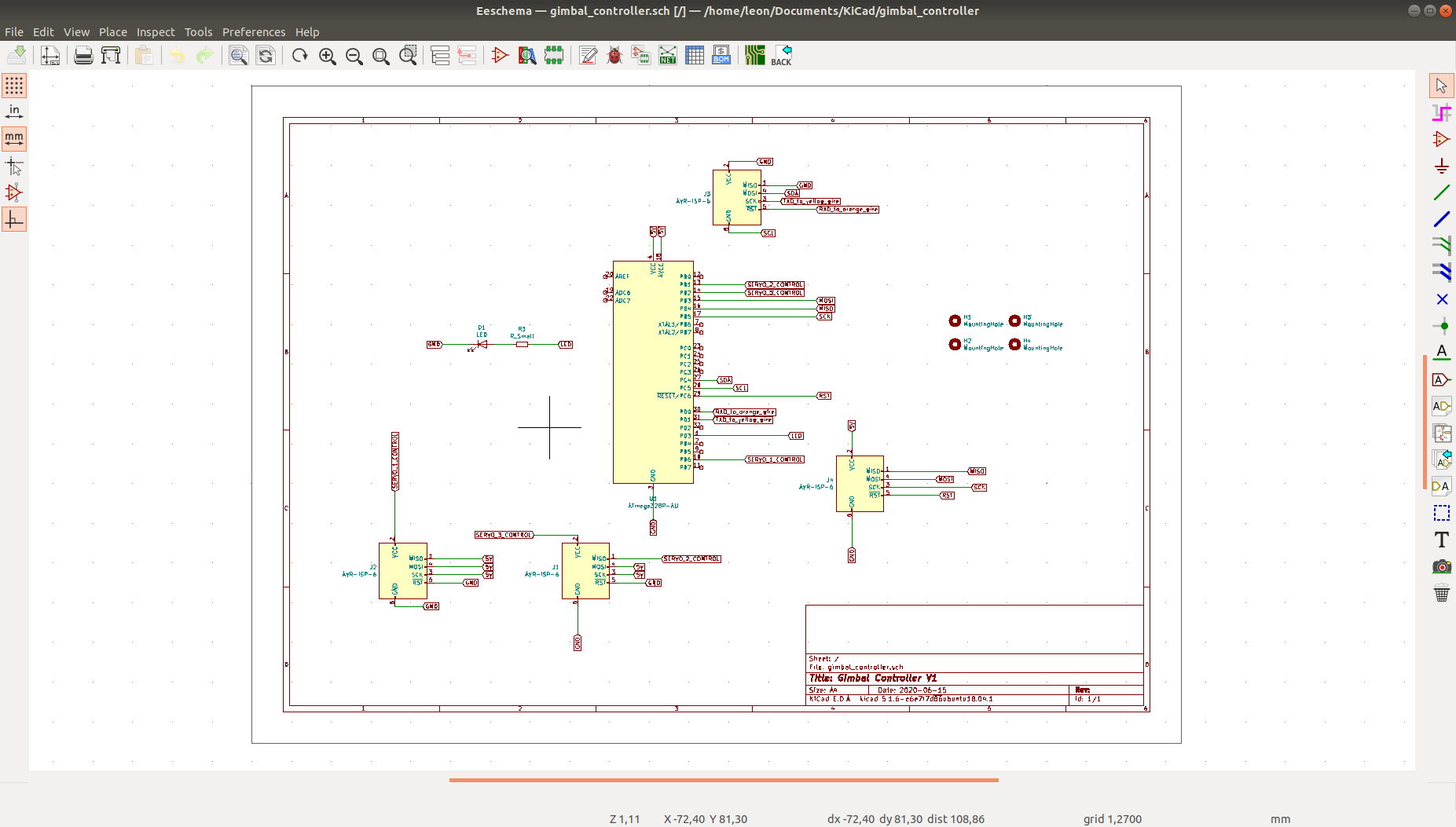
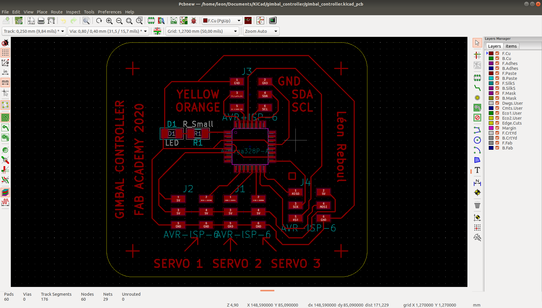
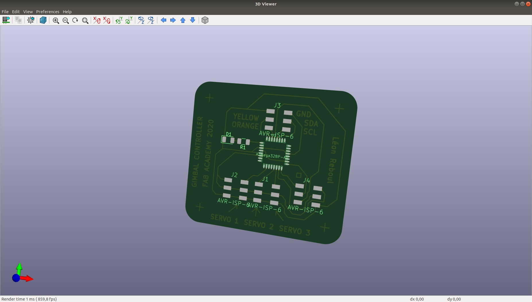
gimbal_controller.kicad_pcb (own work)
gimbal_controller.pro (own work)
gimbal_controller.sch (own work)
test_LSM303D_pololu.ino (Polulu LSM303 documentation)
Week 9 "hero shot":
Figure 0: Read IMU and print IMU data
Table of Contents
Individual assignment
Add an input device to a microcontroller board that I have designed
Already done during week 8! :)Arduino programming
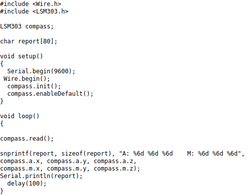
I have use an exeample code from Polulu documentation on sensor LMS303D. Interfacing the input device to the microcontroller is easy when they are available libraries that do the hard work for us...I simply use the demo code from Polulu as a programming process:
Define the object LSMS03 compass (available in the LSMS303 library).
Define a char table of 80 cases.
In the setup function start a serial communication with a baud rate of 9600.
The boad rate must be adequate to communicate.
Start a Wire object (to connect the sensor with the PC)
Initialize the compass
Allow default
The loop function, the code that is done again and again on the ship after uploading the code.
Read the compass.
Print in the char "report" containing the AccelGyroMag data with only the part of the Accel and Mag data from the Compass.
Print the char table in the serial monitor.
Wait for 100 milliseconds.
Read sensor data with my board
Overview of the sensor and the board
Printing the value of the with UART on Arduino serial
Read sensor data with a commercial board
Work done during Covid lockdown
In this section, we will use a raspberry pi 3 with a NAVIO2 hat from EMLID to read IMU data.
Navio2 comes with drivers and exeample, which can be downloaded here.
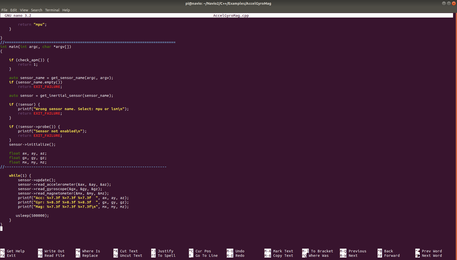
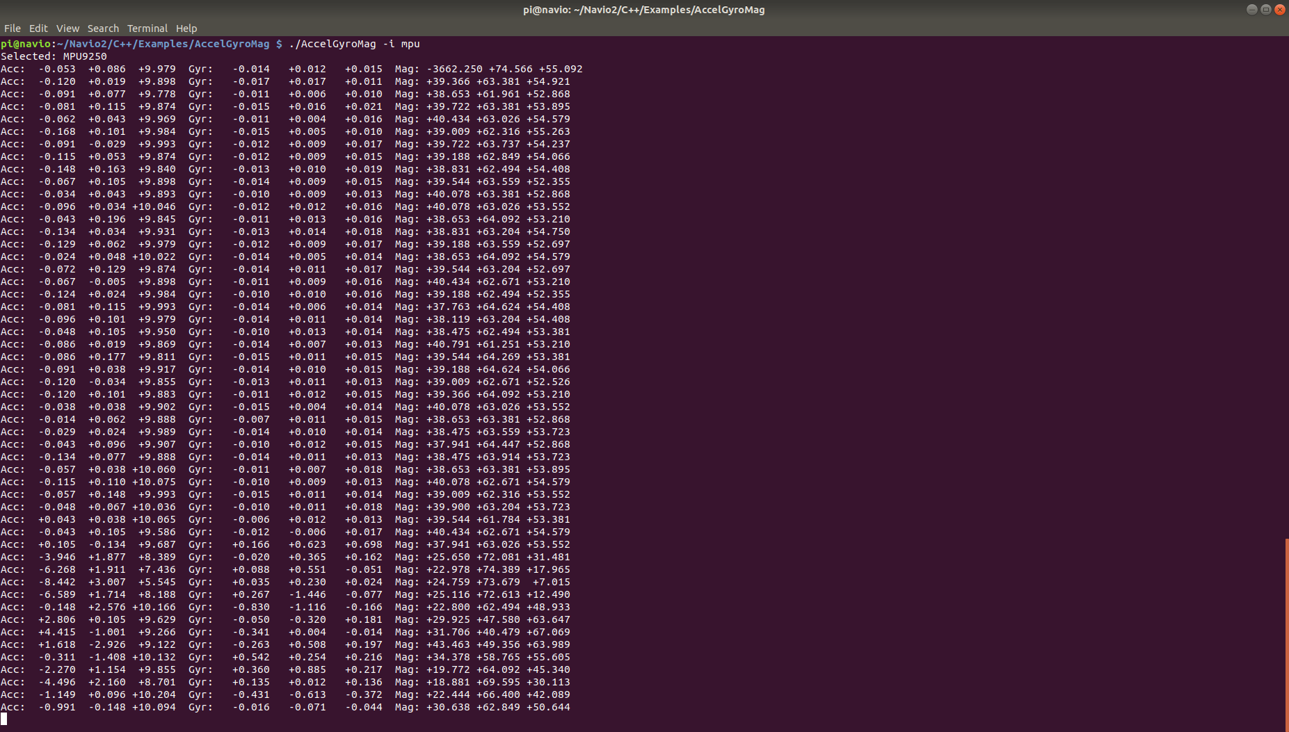
The function "AccelGyroMag.cpp" allows to read IMU data from Navio2 and print the result in the terminal.
Figure 6 shows a snapshot of the code
Figure 7 shows the terminal after running "AccelGyroMag.cpp"
Video 1 shows IMU reading from Navio2 placed inside a fixed wing drone.
