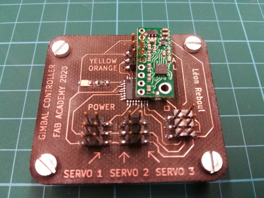
This page presents the assignments for week 8 of Fab Academy 2020: “Embedded Programming”.
To do list:
Group
- compare the performance and development workflows for other architectures
- read a microcontroller data sheet
- program your board to do something, with as many different programming languages and programming environments as possible
Week 8 files:
gimbal_controller.kicad_pcb (own work)
gimbal_controller.pro (own work)
gimbal_controller.sch (own work)
Sweep_test.ino (BARRAGAN and Scott Fitzgerald details inside)
servo_3_test.ino (Modified from BARRAGAN and Scott Fitzgerald details inside)
test_blink_led_2.ino (Michalis Vasilakis details inside)
test_serial.ino (own work)
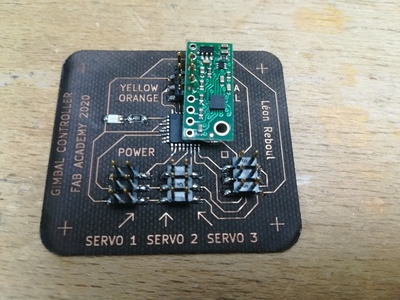
Week 8 "hero shot":
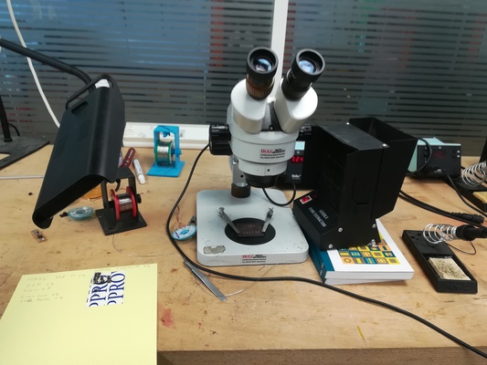
Figure 0: Programming my "Fab Lab made" board to do something!
Table of Contents
Group assignment
To do when the Fab Lab is open again.
Individual assignment
Reading ATtiny45 data sheet
I choose to read the ATtiny45 Data sheet, available online here.Table of contents
Data sheet can be quite large depending on the model, so first it is important to use the table of content to jump to the part that intersest us.
Depending on your browser and/or PDF reader you can use inbuilt navigation as shown left on figure 1 or click on links directly inside the PDF.
Pin configurations
As shown in figure 2, the datasheet provides the pin configurations of the ATtiny45. The pin configuration is usefull for electronic design and production to wire components to the correct pin.
Block diagram
As shown in figure 3, the datasheet provides an overview of the ATtiny45 with this block diagram. The block diagram is usefull to understand the interaction inside the microcontroller.
Architectural Overview
As shown in figure 4, the datasheet provides an overview of the ATtiny45 architecture. The architecture block diagram is usefull to understand the interaction inside the microcontroller.
Diagram for 328p pinout
I used the figure bellow to help me design my boards. I also used it to adapt my arduino code. For exeample I used the pins 6, 9 and 10 in the file "servo_3_test.ino" as they are of type PWM.Design and make my board
I used this week to design a gimbal controller for my final project.Specification
I want the board to be able to- control 3 servos
- read input data from an IMU sensor using I2C protocol
- talk with a PC using UART protocol
- be programmable using the ISP I made in week 4
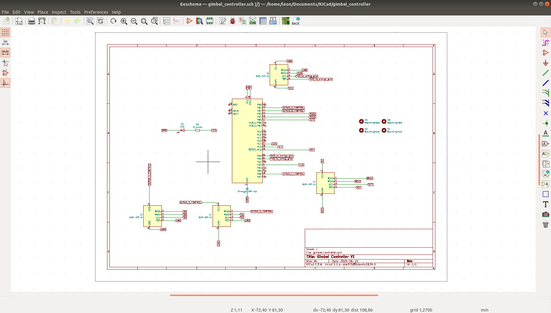
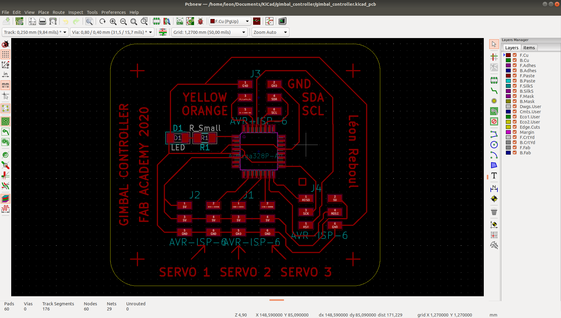
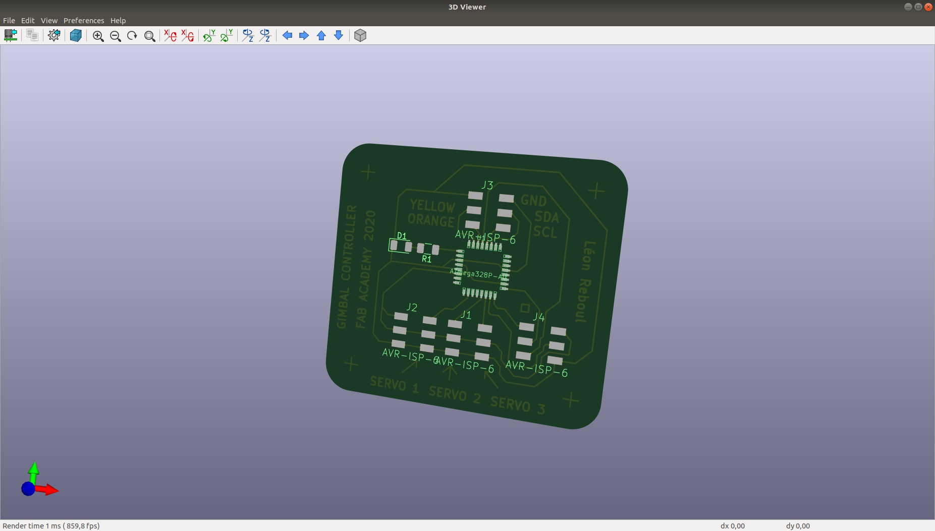
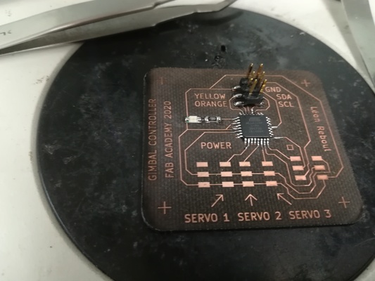
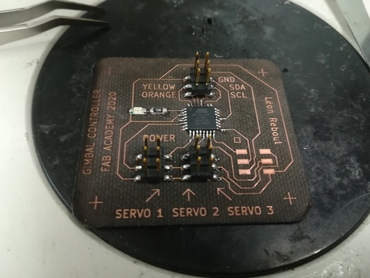
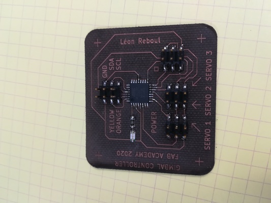
Design of the board with Kicad
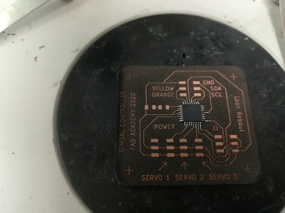
First design
Second design
Third design
Making the board
Laser cutter
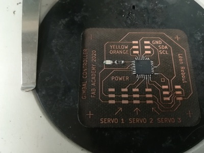
Soldering
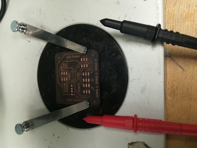
First designSecond design
Program my board to do something
Rotate a continous servo using arduino code with arduino IDE, avrdude and week 4 programmer
Servo rotation
Print a message with serial
Video 1: Print "Notice me" on screen using USART communication
Blink the led using C++ code with ATMEL STUDIO and ATMEL ICE
Blink a LED
Program a commercial board to do something
Work done during Covid lockdown
In this section a raspberry pi 3 with a NAVIO2 hat from EMLID is programed to read sensor inputs.
Documentation
The "NAVIO2" is an autopilot hat for raspberry pi, powered by ardupilot and ROSFigure 5 shows how to attach the Navio2 hat to a raspberry pi.
The Navio2 can provide power to the Raspberry Pi using a power module as shown in figure 6.
Programming
Navio2 IMU example
Navio2 comes with drivers and exeample, which can be downloaded here.The function "AccelGyroMag.cpp" allows to read IMU data from Navio2 and print the result in the terminal.
Figure 6 shows a snapshot of the code
Figure 7 shows the terminal after running "AccelGyroMag.cpp"


