This page presents the assignments for week 4 of Fab Academy 2020: “Electronics production”.
To do list:
Group
- characterize the design rules for your PCB production process
- make an in-circuit programmer by milling and stuffing the PCB,
- test it,
- then optionally try other PCB processes
Week 4 "hero shot":
Table of Contents
1 Group assignment
I worked with
Serena, Benoit and Jonah (Fab Manager) to characterize the design rules
for the PCB production process with the laser cutter of the Lab.
1.1 Overview
1.2 Step by step PCB design process
Step 1
Import the .png file describing the PCB in corelDRAW as shown in figure 1.
Step 2
to open the print menu as shown in figure 2.
Step 3
Select the
appropriate parameters, reading the data sheet of the laser cutter, to
raster with the fiber laser, as shown in figure 3.
Step 4
At this step the PCB should look like as in figure 4.
Step 5
Be careful to put it inside the zone where copper have been removed, as laser isn't powerful enough to go through the copper.
Step 6
Step 7
Select the appropriate parameters, reading the data sheet of the laser cutter, to vector cut with laser.
Step 8
If everything worked fine remove the plate from the laser cutter as shown in figure 5
Step 9
If you have been to
impatient and didn't make enough pass of the laser, use a utility knife
to painfully cut the fiberglass as shown in figure 6.
Check PCB design
Use a microscope to check for hair as shown in figure 7.
Individual assignment
I have follow the tutorial of Brian on how to make a FabTinyISP.
Introduction
As stated in
Brian's tutorial: “The FabTinyStar is yet another version of an AVR ISP
programmer/board that can be produced in a fab lab using a milled PCB
and readily available components. The project is based on the efforts of
many people. For more history of the FabTinyStar and the people who
have contributed to it, please refer to Zaerc's FabTinyStar page”.
PCB Fabrication
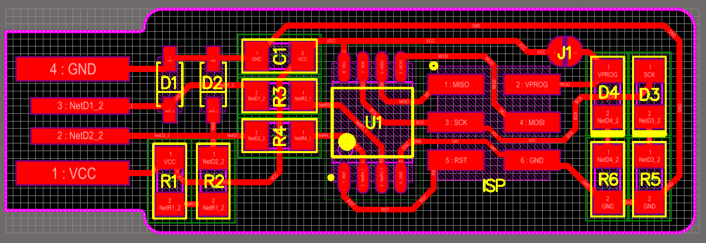
Download the trace and the outline and use the step described in the group assignment section to obtain this PCB.
Figure 8 shows the PCB after the laser cutting steps
Assembling the PCB
Step 1
Wrote down all the name of the parts on a paper in one column and put a double sided tape right to it.Step 2
Pick up each piece on the inventory of your Lab.Step 3
Glue the piece near it corresponding name as shown in figure 9.Step 4
Step 5
Step 6
Figure 12 shows my PCB with all the soldered parts.
2.4 Improve USB connector
2.5 First checks for the PCB
As shown in figure 13, the red led is on when the PCB is connected to a computer.
2.6 Software installation
Step 1
sudo apt install avrdude gcc-avr avr-libc make
2.7 Get and build the Firmware
Step 1
Step 2
cd
Step 3
make
Step 4
ls
Figure 14 shows the terminal output after running the command:
make
2.8 Program the ATtiny45
Step 1
nano Makefile
PROGRAMMER ?= usbtiny
to the programmer name you are using as shown on figure 15.
Step 2
Connect the programmer to the ISP header on your board. Figure 16 shows a “atmelice_isp” programmer connected to the board.
Step 3
make flash
Terminal output should like the one in figure 17
Step 4
make fuses
Terminal output should like the one in figure 18
2.9 Test the USB functionality
Step 1
Step 2
Step 3
Step 4
lsusb
If you see a "Multiple Vendors USBtiny" device on the list as in figure19, then it worked!
2.10 Blow the reset fuse
Step 1
make rstdisbl
Step 2
2.11 Test your programmer
But programming was successful as shown in figure 20.


