This page presents the electronics parts for my final project.
Electronics design
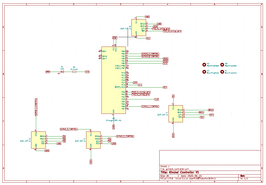
KiCAD schematics
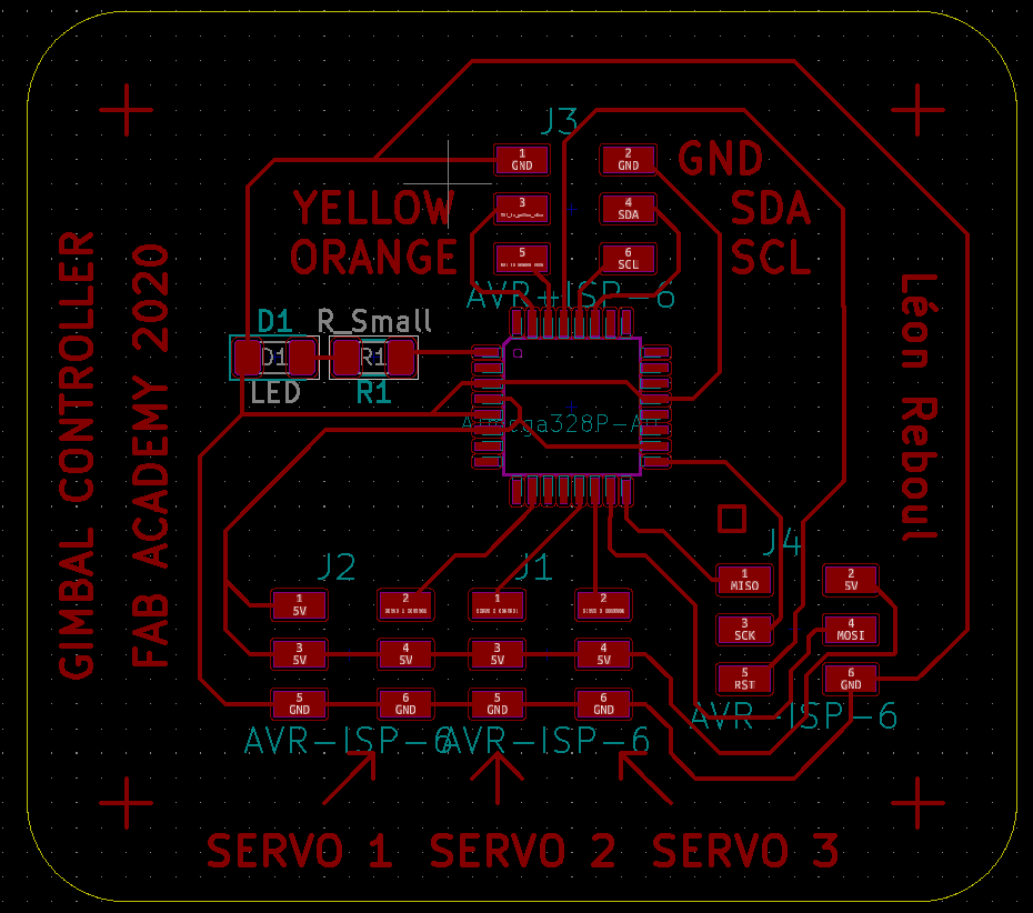
KiCAD PCB
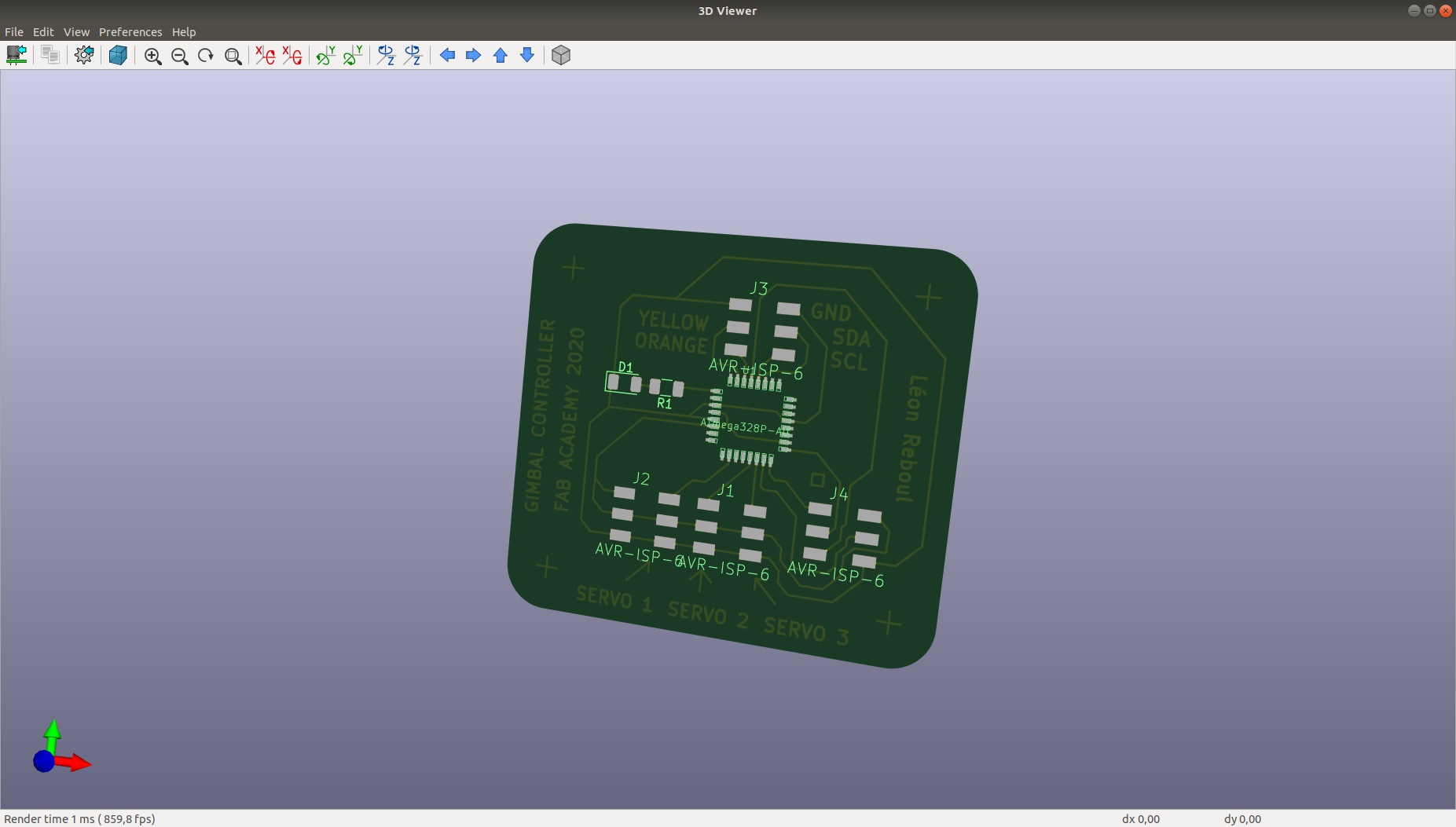
PCB 3D view

SVG for the laser cutter
Electronics production
Steps of production of gimbal controler V2
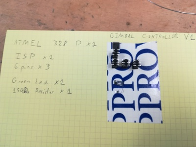
Prep sheet before soldering for V2
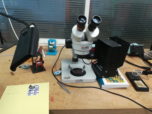
Set up to soldering V2
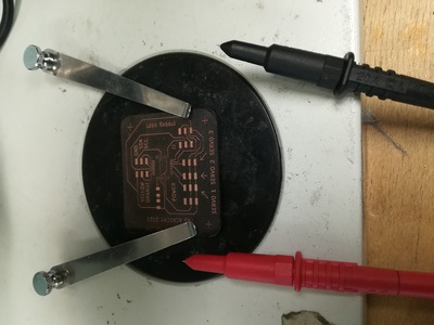
Check the board with beeping oscilloscope
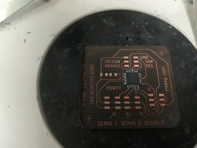
Soldering V2 board microship
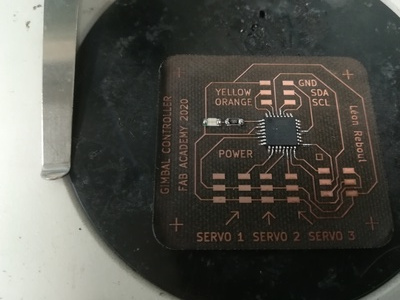
Soldering V2 board led and resistor
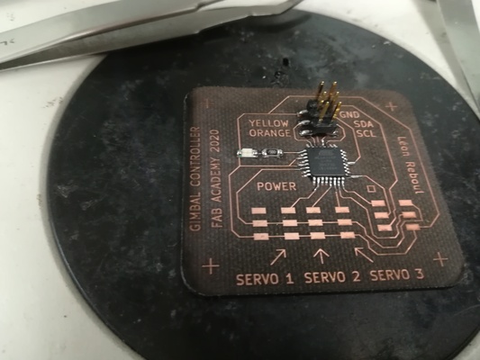
Soldering 6 pins header for
UART and Sensor wires
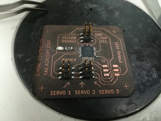
Soldering 6 pins headers for
power, servo 1, 2 and 3
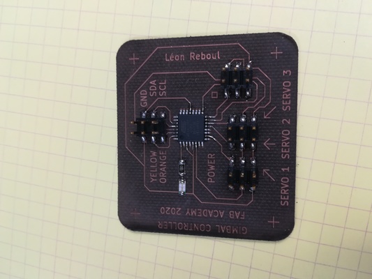
Soldering 6 pins headers for
ISP
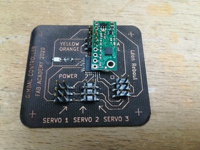
Soldering LMS303D sensor
directly on the board
Mistake! :(
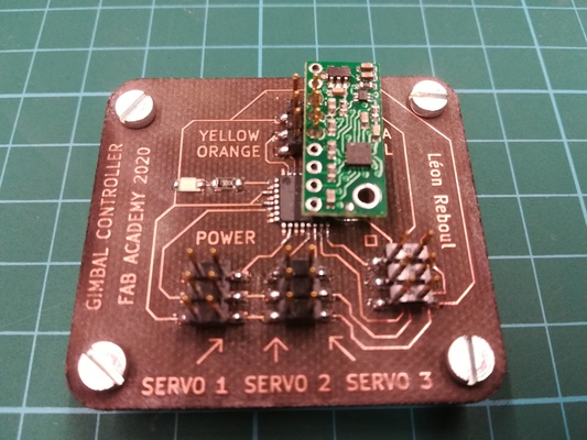
Board with screws after
drilling fibberglass (under fume hood)
Electronics integration
In this section I present the integration of the electronics in the drone.
Integration of the electronics components on a modular board
I wanted the drone to be as modular as possible.
That is why I designed the integration electronics on a modular board.
This modular laser cutted wood board hold all the vital electronics of the drone:
- battery,
- electronic speed controllers (ESC) for the motors,
- receiver,
Depending of the mission, one can the following to the board:
- an autopilot
- a raspberry pi to process data from embeded sensor
The figures bellow show the modular board V1, the battery and the two ESCs strapped and the back of the gimbal controler with adhesive velcro glued on it.
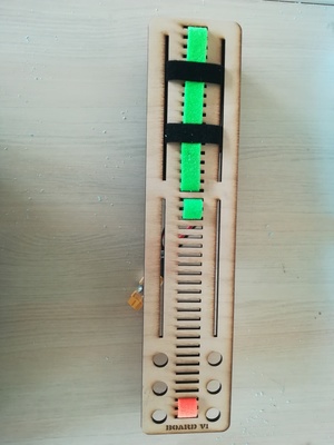
Modular board V1 top view
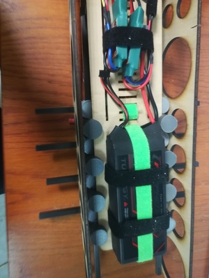
Modular board V1 bottom view, battery and ESCs strapped on
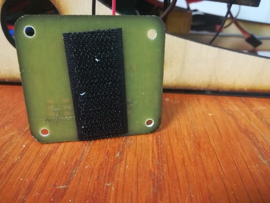
Gimbal controler with adhesive velcro glued on it
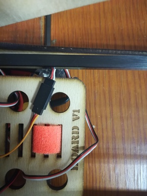
Velcro scotch for the PCB on the modular board
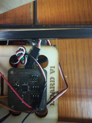
Gimbal controler strapped on the modular board
This system (multiples holes, velcro scotch and adhesive) allows great modularity and allows to move easily the parts on board.
The goal was to allow the user to easily balance the drone before the flight.
The design of the board is done with OpenSCAD. One can easily modify the OpenSCAD code to adapt the board to is need before the laser cut job.
Integration of the modular board inside the drone
I designed the integration of the board inside the drone by looking at racks inside a server.
The idea was to allow the user to easily and quickly put the board inside and out of the drone.
I designed 3D printed connector to allow to connect the carbon tube and to slide the board in and out.
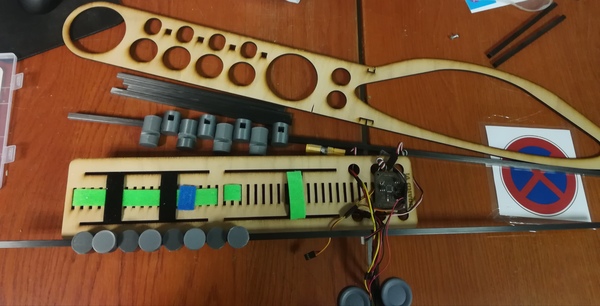
Modular board and carbon tubes with 3D printed connectors
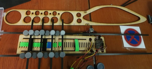
Board slided in and one laser cut fuselage side

Both side of fuselage and the gimbal system on the carbon tube.
Note that the short carbon tubes are only used for illustration purpose.
During the drone build the full carbon tube are used (1 meter), as show in the picture bellow.
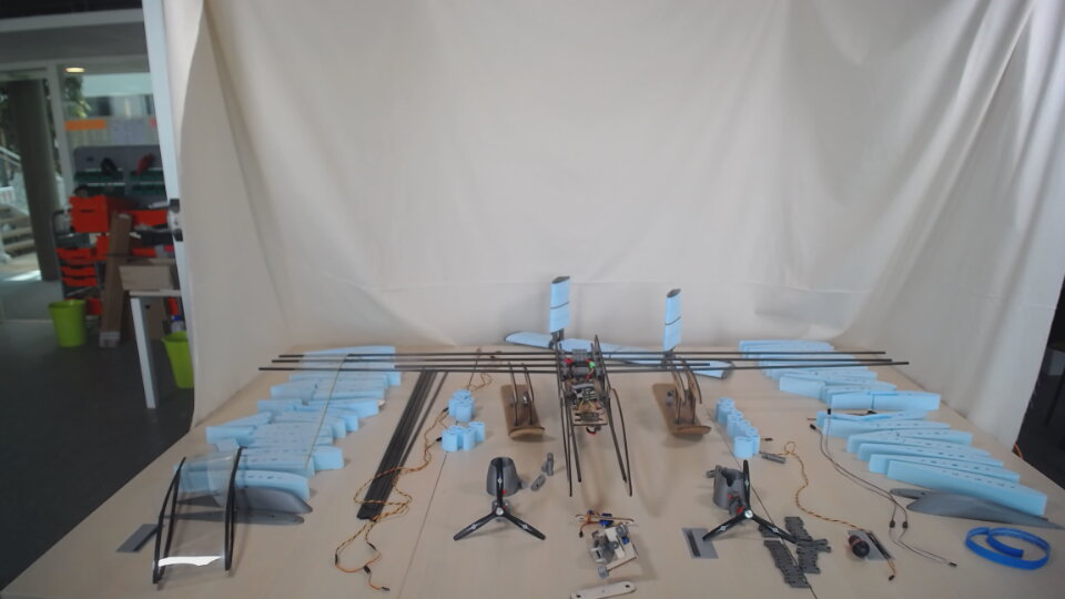
Carbon tubes and the modular board
Integration of the sensor into the drone
The idea was to be able to slide the modular board in the 3D connectors then to slide the gimbal holding the sensor on the carbon tubes.
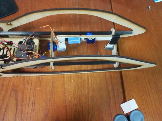
Gimbal slided on the carbon tubes.
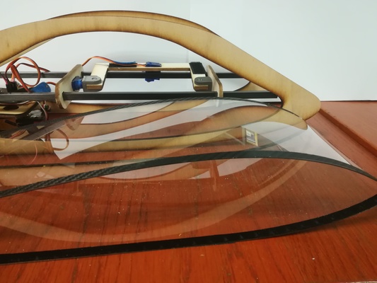
Clear acrylic off the fuselage
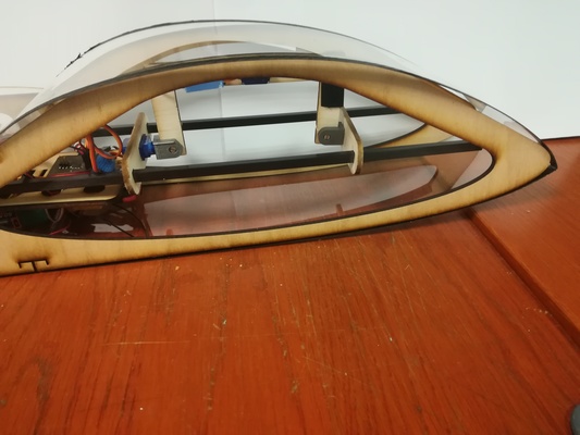
Clear acrylic on the fuselage
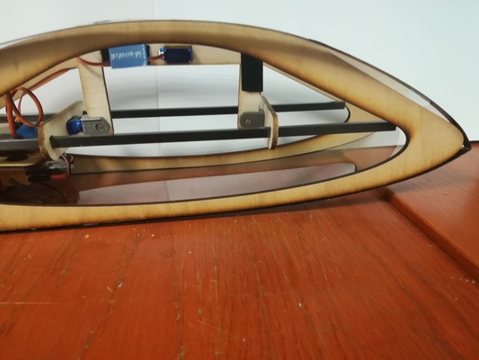
Fuselage design to allow the gimbal to move freely inside
The gimbal is composed of laser cut wood and 3D printed connectors.
Let the "end connector" be the 3D printed connector, that link the sensor to the servo used for pitch compensation.
One can modifiy this connector and the length of the laser cut wood to fit a large variety of sensor.

Gimbal with "end connector" linked to a camera.
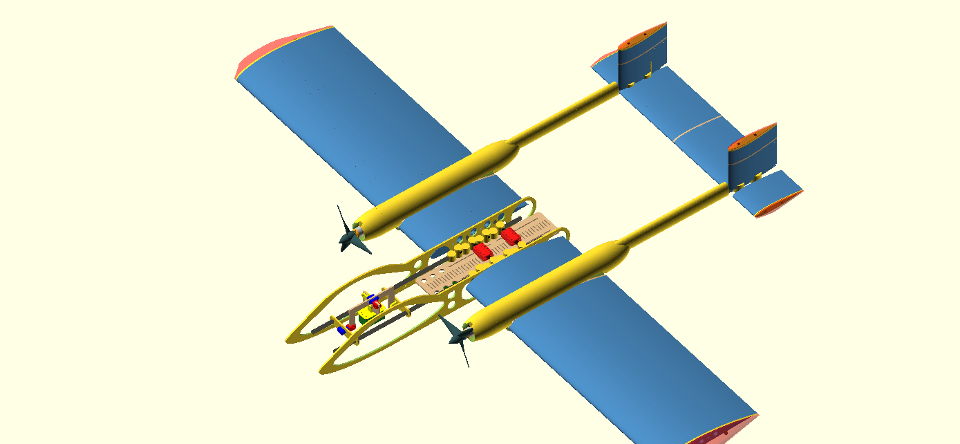
CAD of the gimbal and sensor
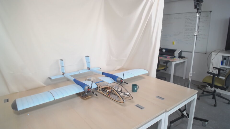
Full drone with the sensor inside


