Notes + Scribblings
This week... was kinda crazy. I went to Charlotte, NC and ended up videoing in for the lecture Greg did on CNC milling.
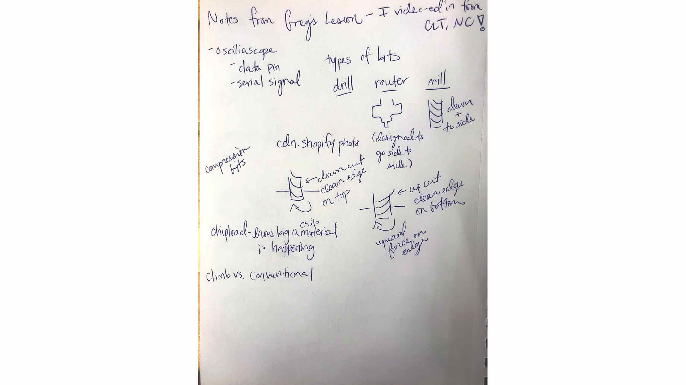
The notes I took.
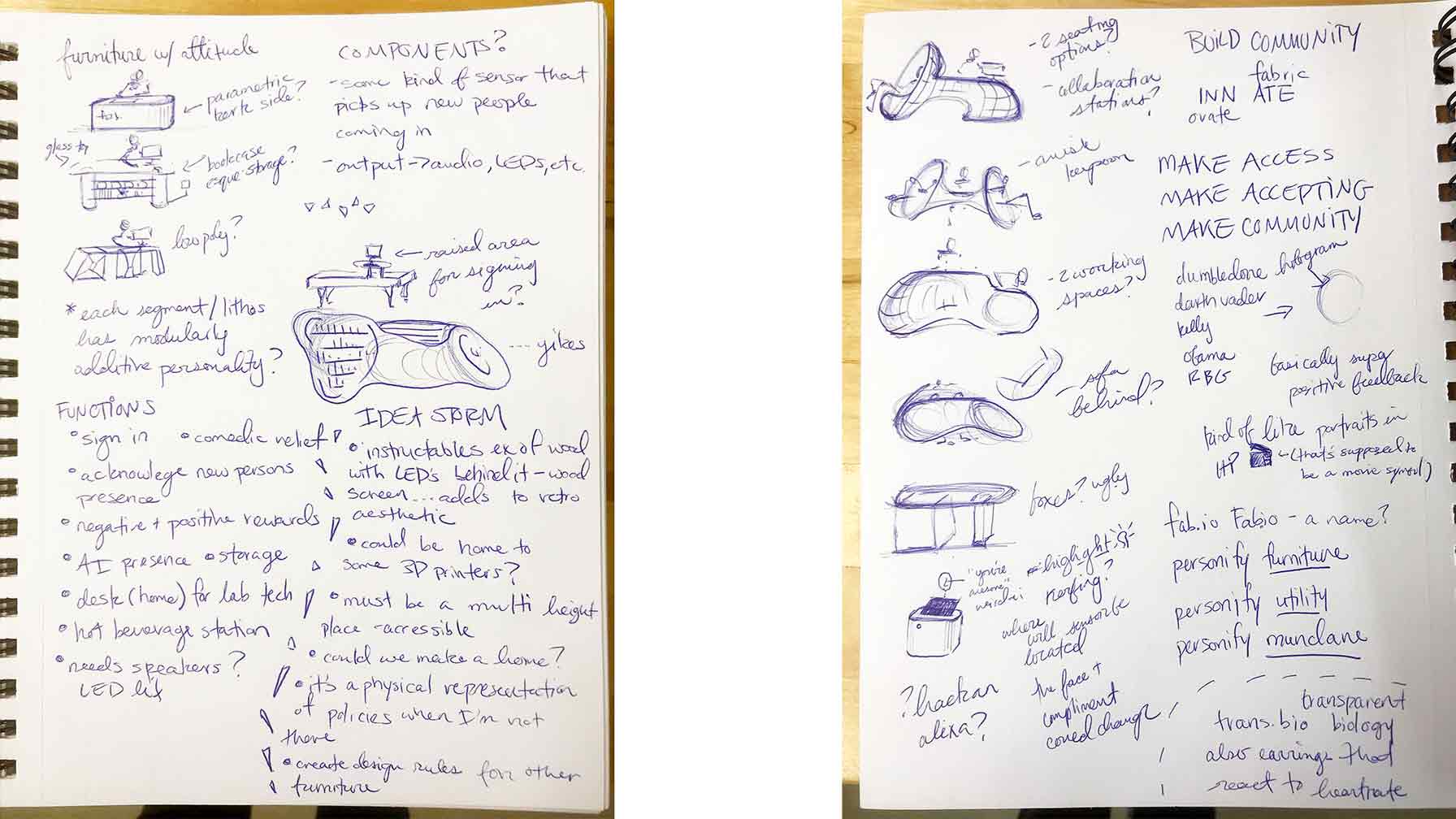
The scribblings began...
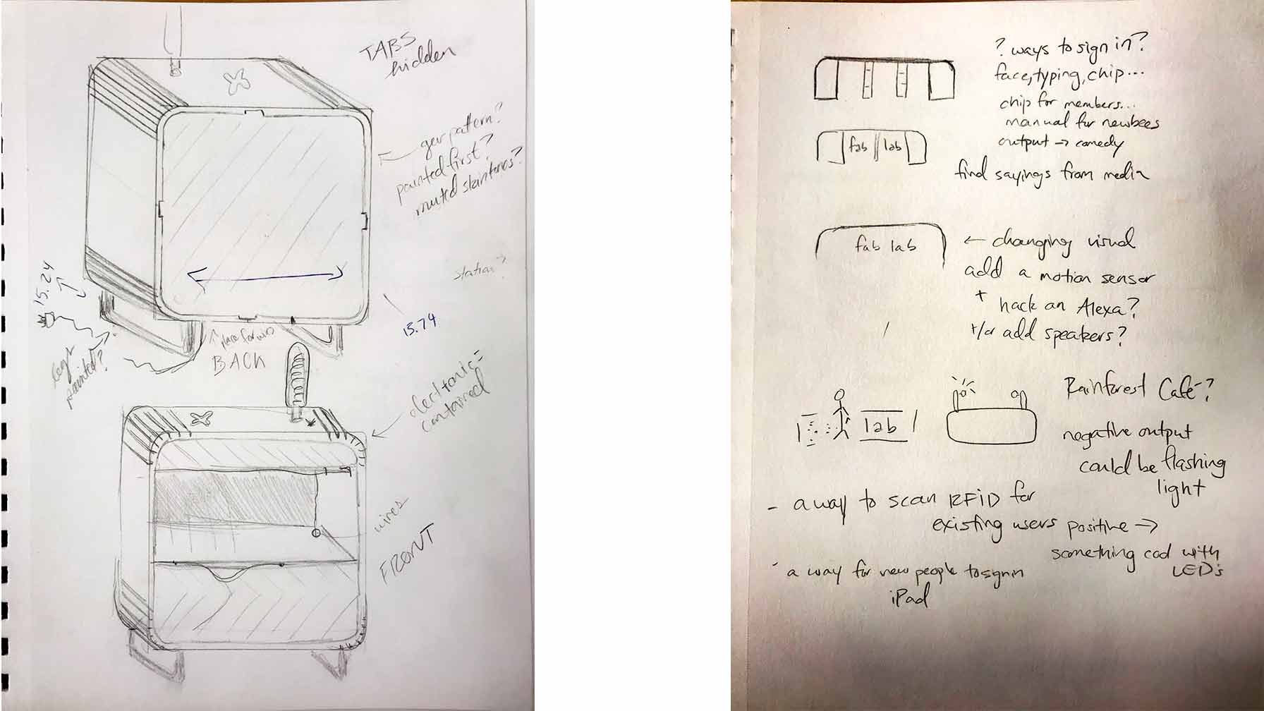
A minitaure version of what I'd like to make for my final project.
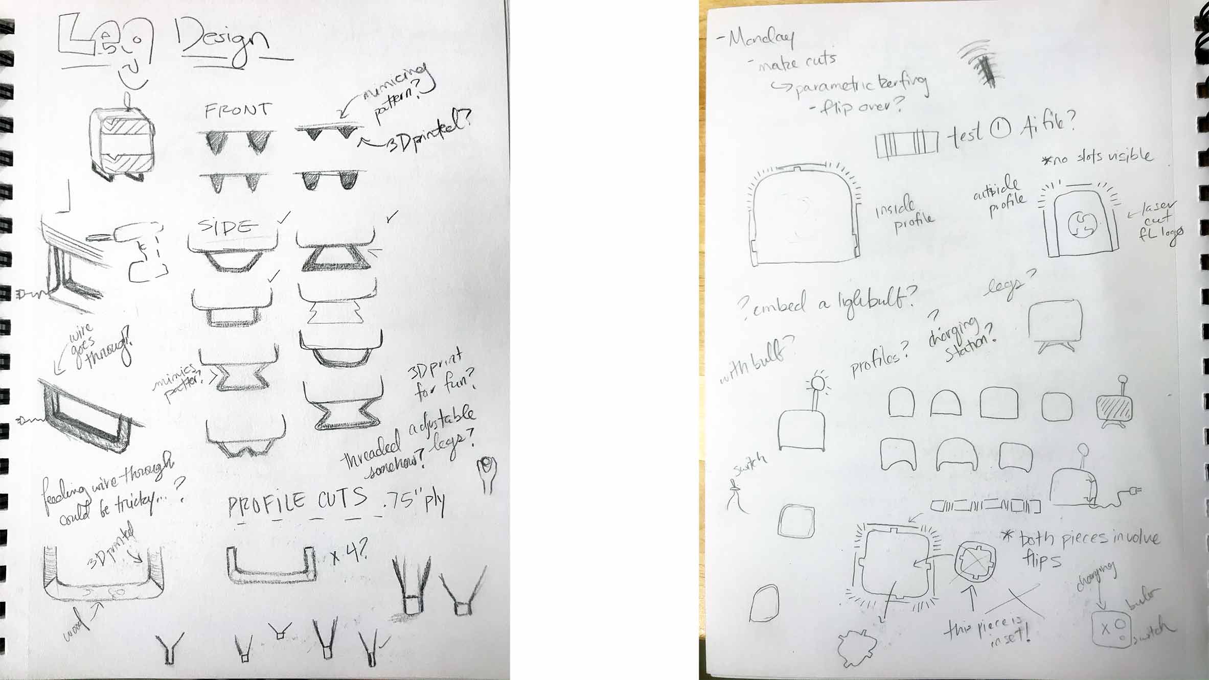
Ideas for profiles and legs.
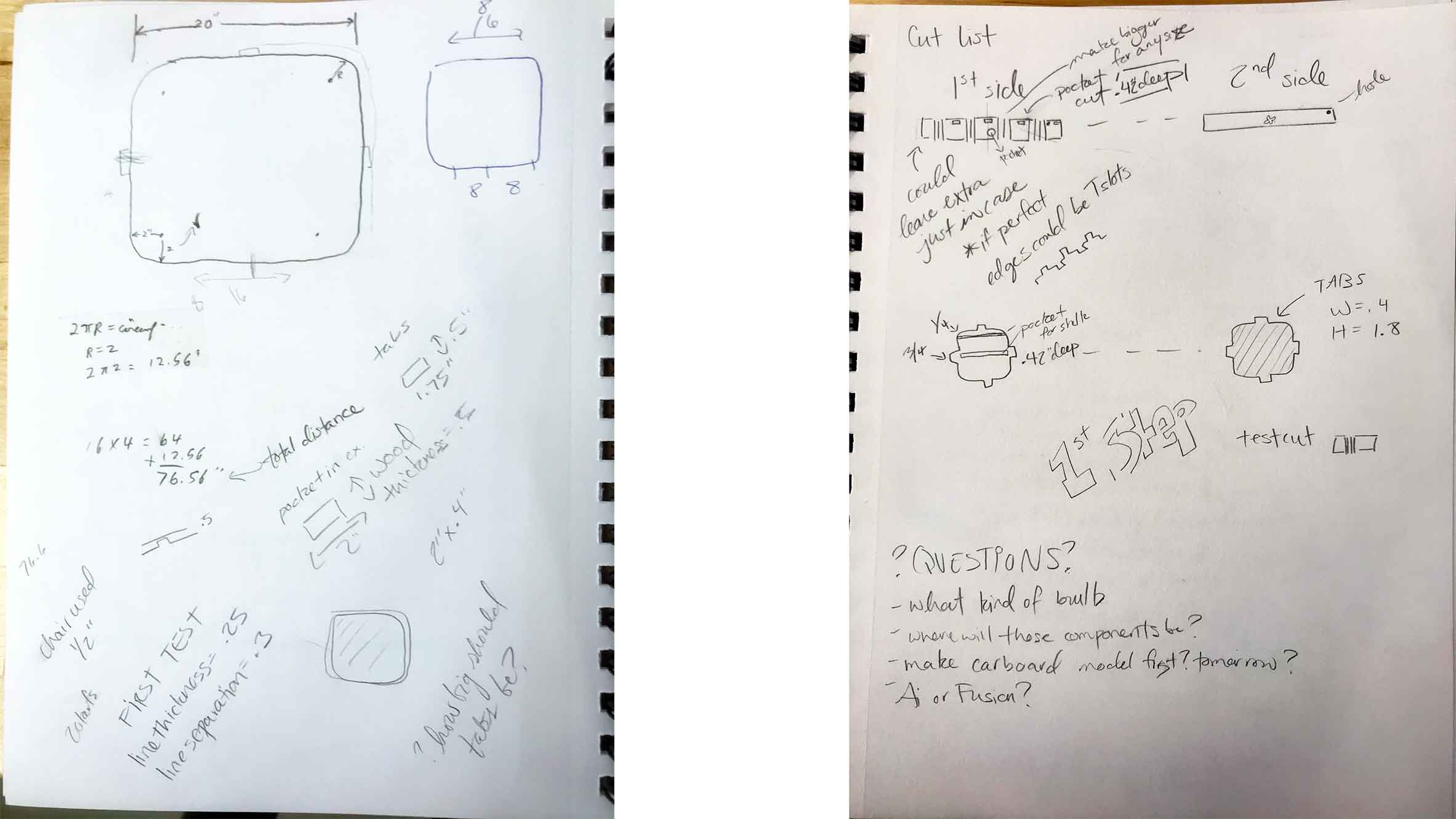
Time to do some math... and think about how to make the files...
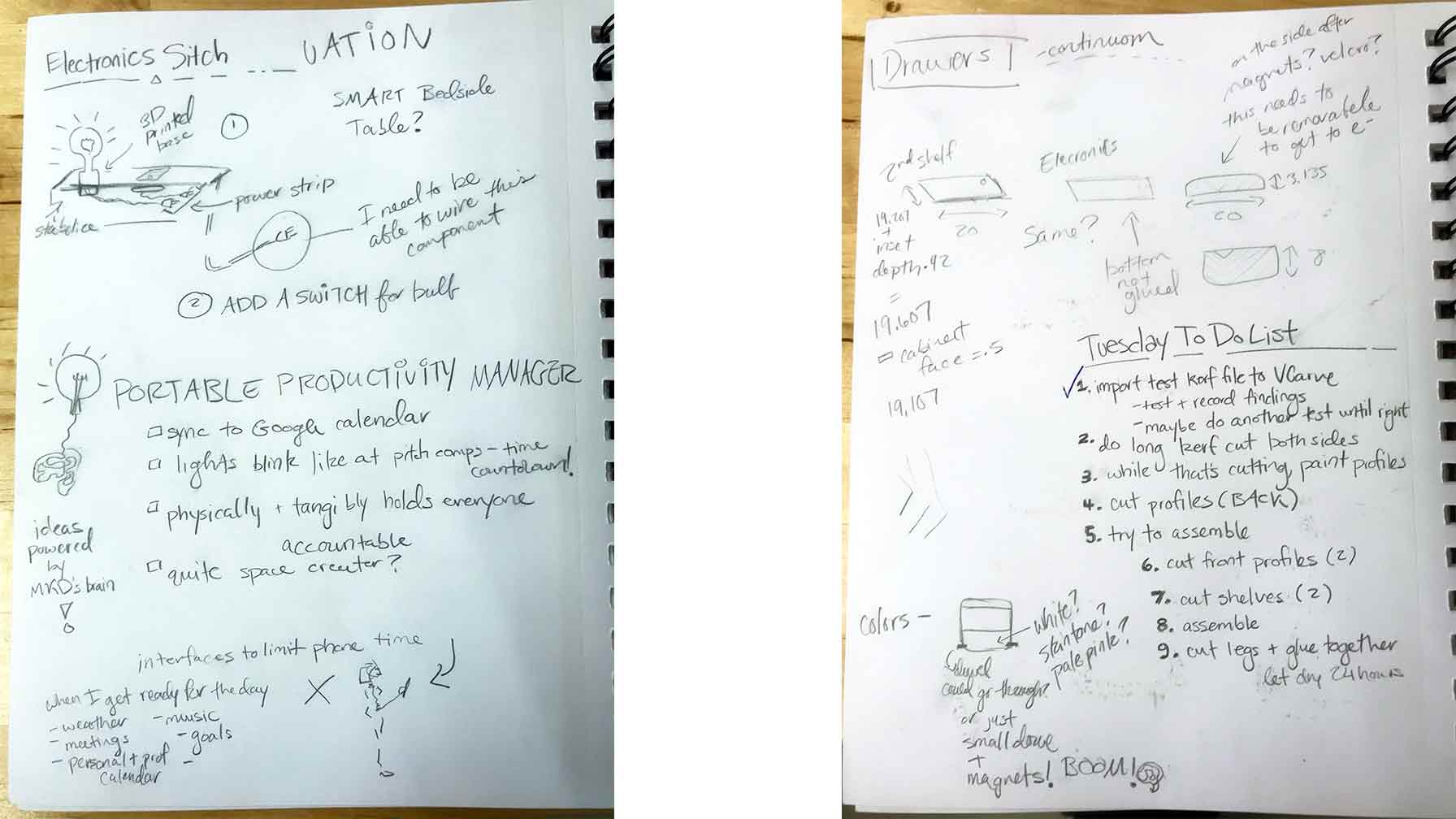
Time to come up with a plan... not sure why I put Tuesday... I started this Monday.
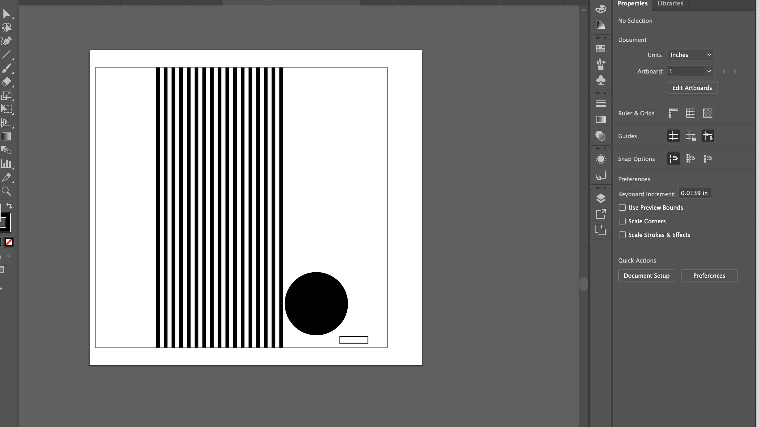
I decided to use Illustrator to make my files... this was a hard decision... other option in my mind was Fusion or Blender. The reason I chose Ai is becuase in my mind this was really more like a piece of fabric I was sewing together... and in that since it starts off 2.5 D and ended up 3D. Essentially it didn't really become 3D until I assembeled it.
CAD + CAM
So I do realize it is unconventional to use Illustrator as my design software. I kind of wanted to prove it was possible to make a well made 3D object using a vector based software. Additionally, I wanted to discuss my decision to use VCarve and not the another option of creating toolpaths using Fusion 360. While I VCarve gets a bad rep sometimes, it was relatively easy to figure out and when I'm dealing with the cnc, safety is one of my highest priorities. I like that it's quick and not connected to the cloud and that because it's used by others, there's a decent tool library already saved.
I used V Carve to create the toolpaths. While this software is very limited and you can only really alter 2.5 D drwings, it's easy to use and Dassault has it. It is not free.
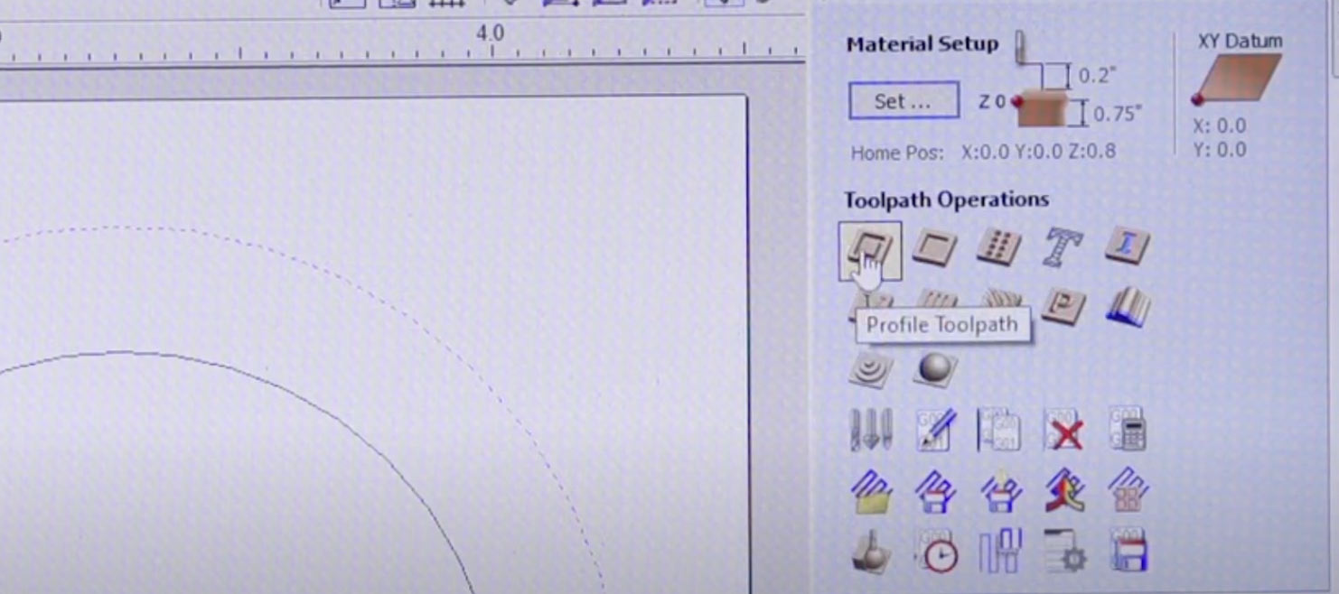
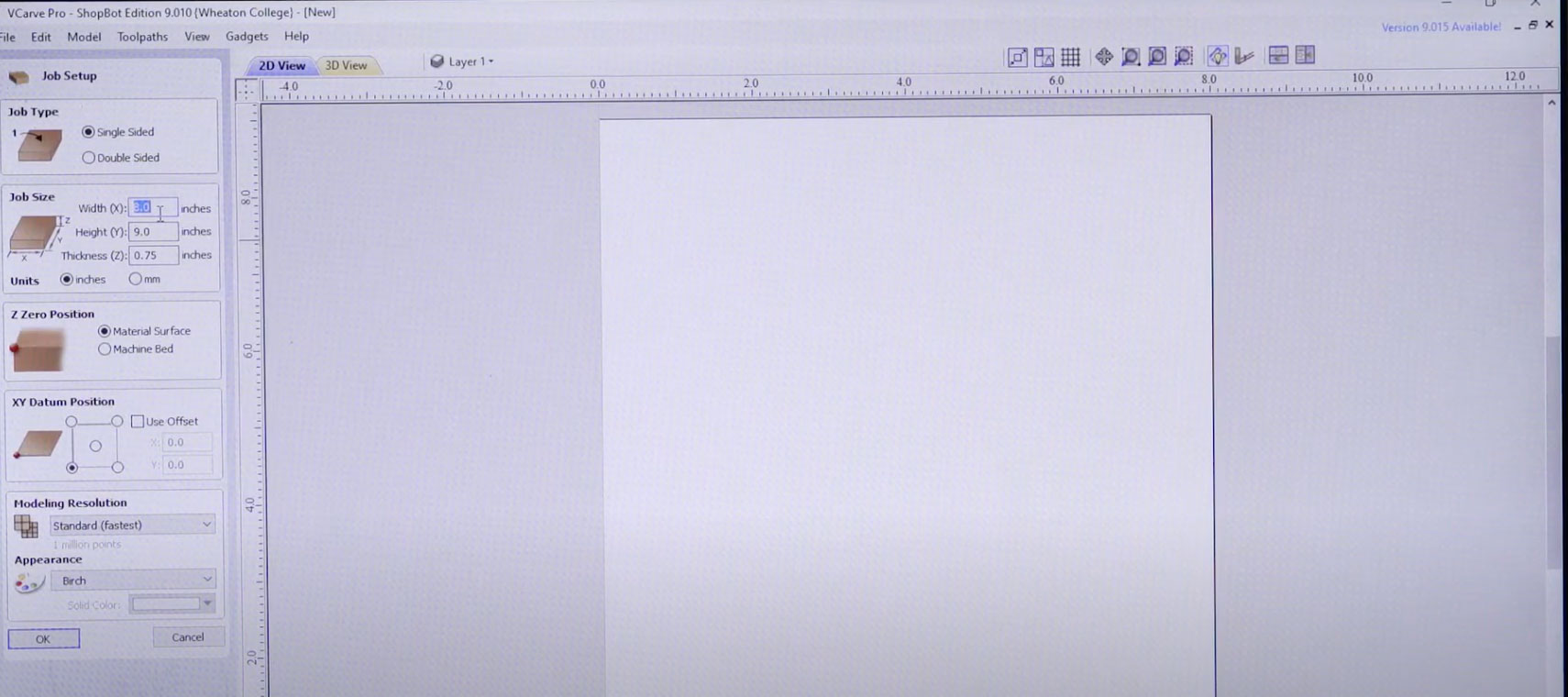
There are serveal important steps when it comes to creating a toolpath and I will point out a few. Selecting a toolpath is among the first things you have to do once you have set your material parameters. Almost all of my cuts for this project were profile. The few pocket toolpaths I did, ultimately were not used.
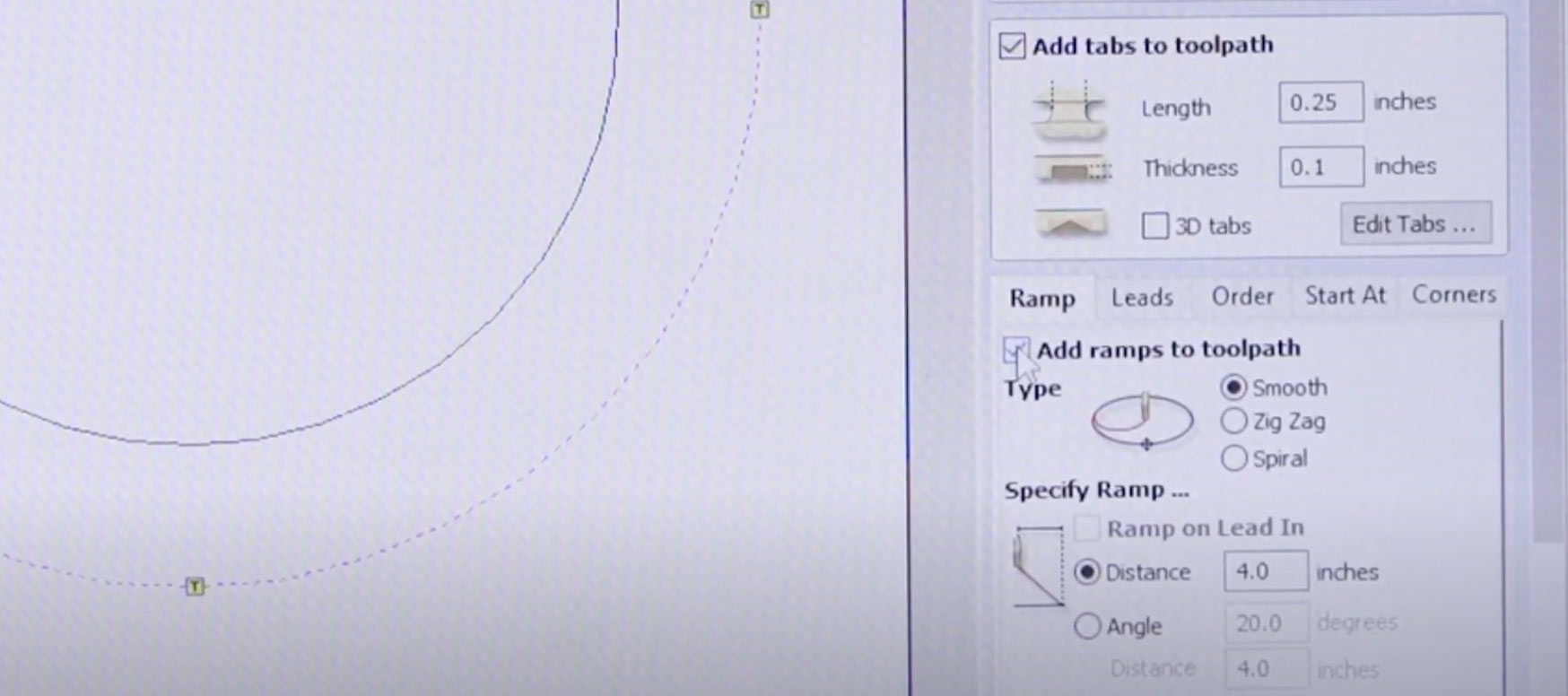
This is how you add tabs and ramps. Tabs are crucial if you are doing profile tooldpaths and are even slightly concerned with the material staying on the buildplate. Some CNC's have suction that hols the material down and in some cases with those, you wouldn't need tabs. Ramps help to maintain your drill bits... using a ramp is a slower more gradual plunge into the material and in my opinion is better than diving right in.
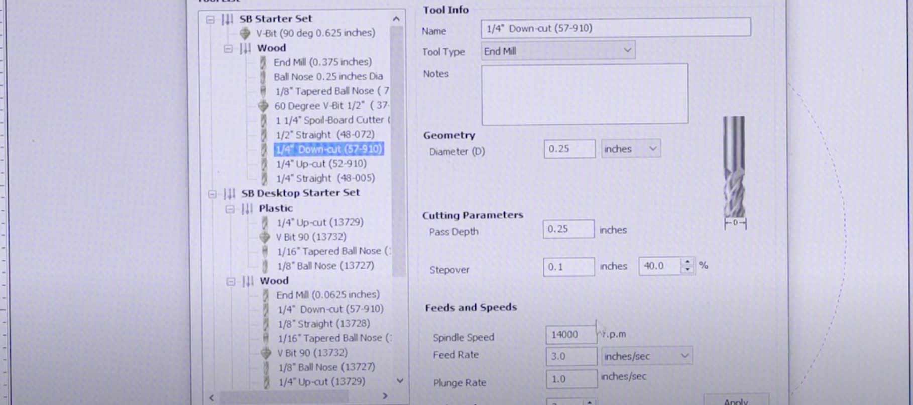
Like I said before, choosing the right bit is SUPER important! This is how you choose the bit in VCarve. Different bits are intended for different feeds and speeds as well as materials. If you choose the wrong bit you could have less than ideal results for your project but you could also break the bit which is never fun... because it could hurl across the room and hit you or something else.
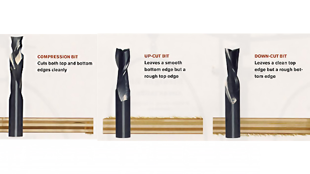
Really like this diagram of how bits work. I ended up using a quarter inch down cut bit. This makes your material on the bottom look somewhat rough but the top its usually okay. They also have compressions bits which bring the material to the middle and don't sacrifice either side of the board.
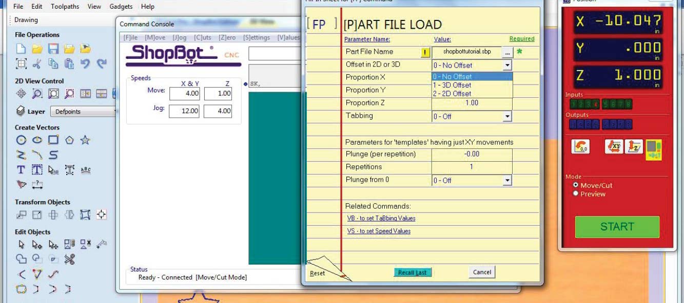
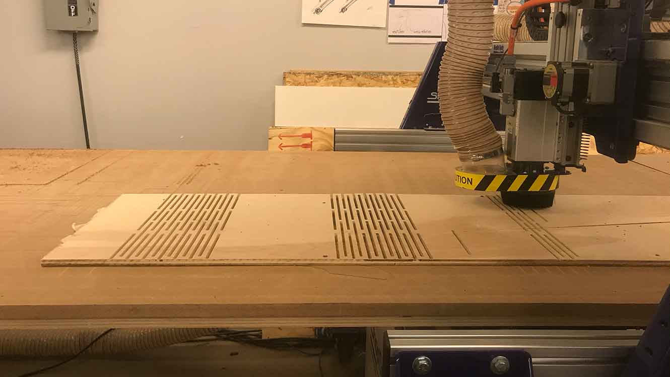
This is an image if what the ShopBot software side of things looks like. I think thw most important part of this is the red panel on the right. This is how you access the other aspects of the ShopBot software and it's also how you start a job.
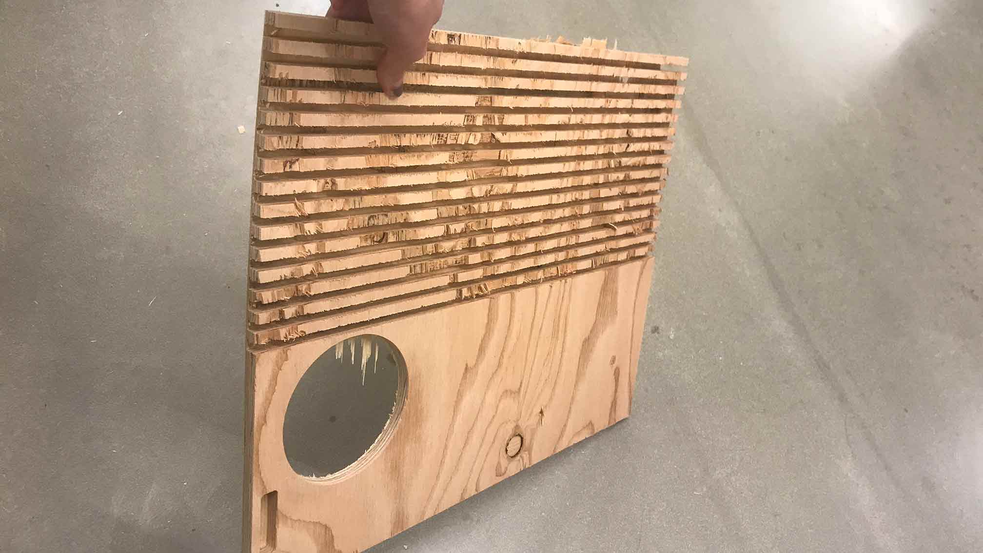
So this didn't work. It had no flex and it was super rough... the cuts very very jagged and there was too much splintering. My instrucotr Luciano suggested that this also could have been changed if I modifyed the feeds and speed which I agree with.
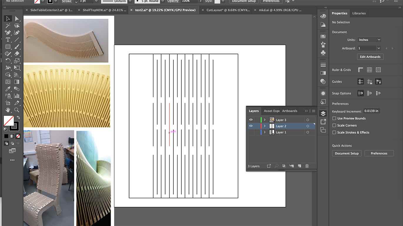
This is the photo Neil linked. I used this to freehand this vector. I also used this video to inform the design.
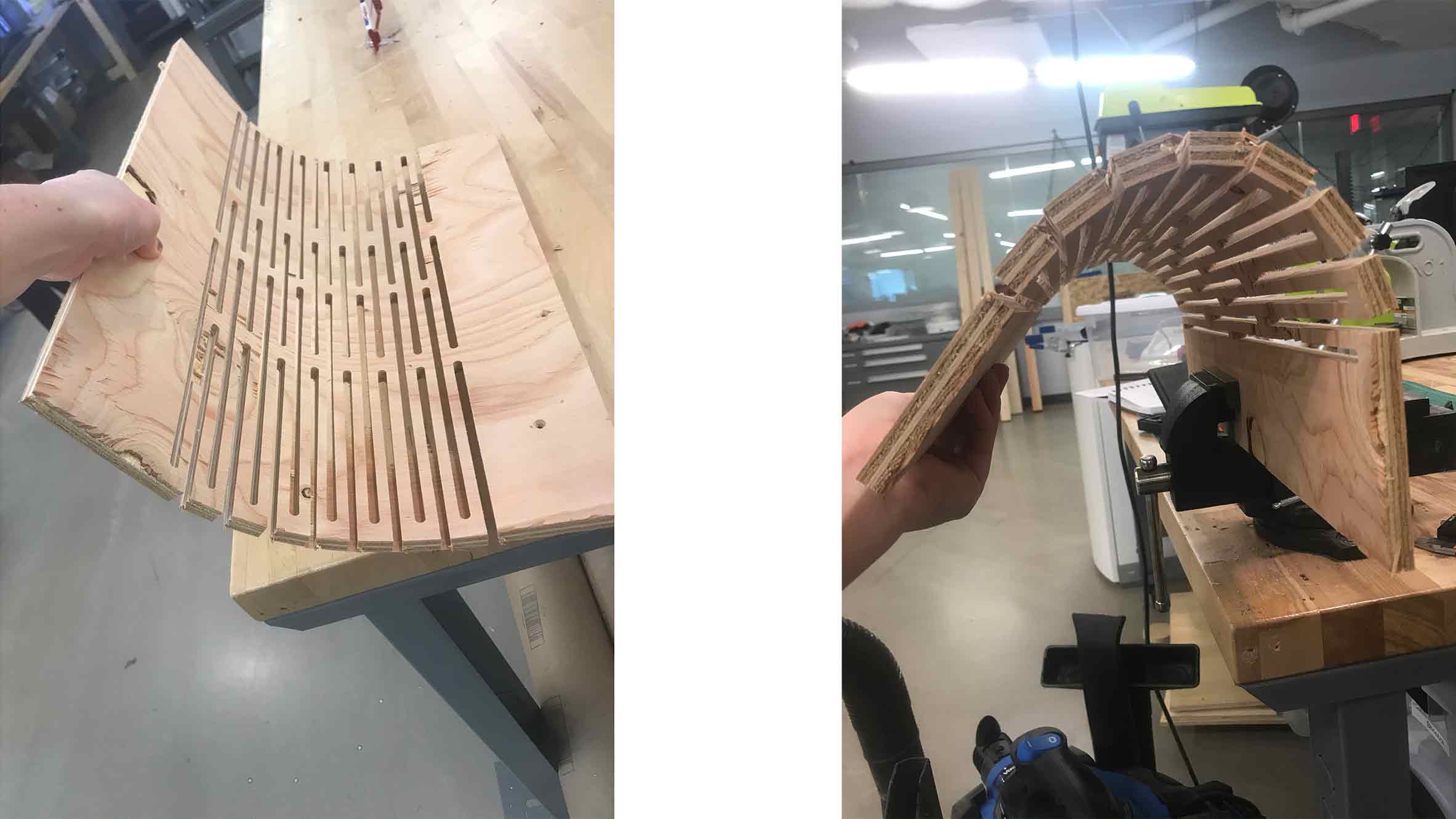
This had much more flexion and seemed like it could get the job done.
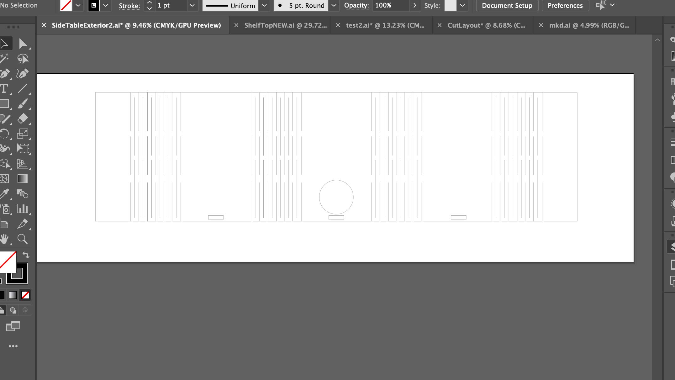
Here is what the vector looked like.
I had to stop this cut so many times. The cuts were too close together and there was nothing to hold them down. That's the Zina! She is taking FabAcedmy with me.

A few things went wrong. You can see here how little I could actually cut through as well as how much was chipping off.
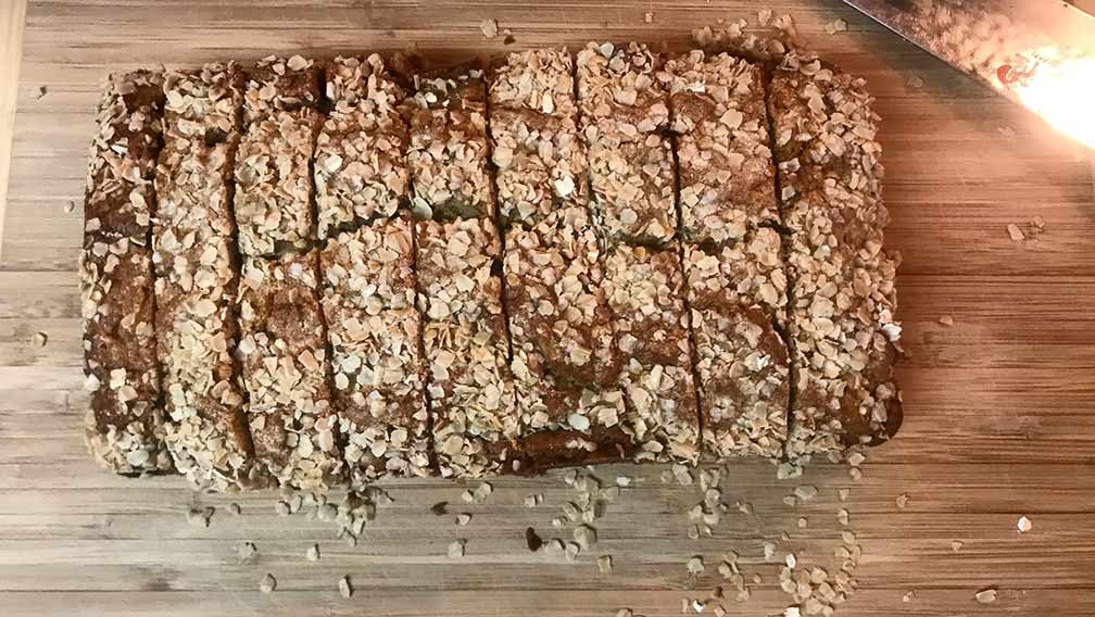
I was feeling kind of down after today with everything going on... the lab I have been going to shut down and so did my work lab... I love to make. I often cope with baking.
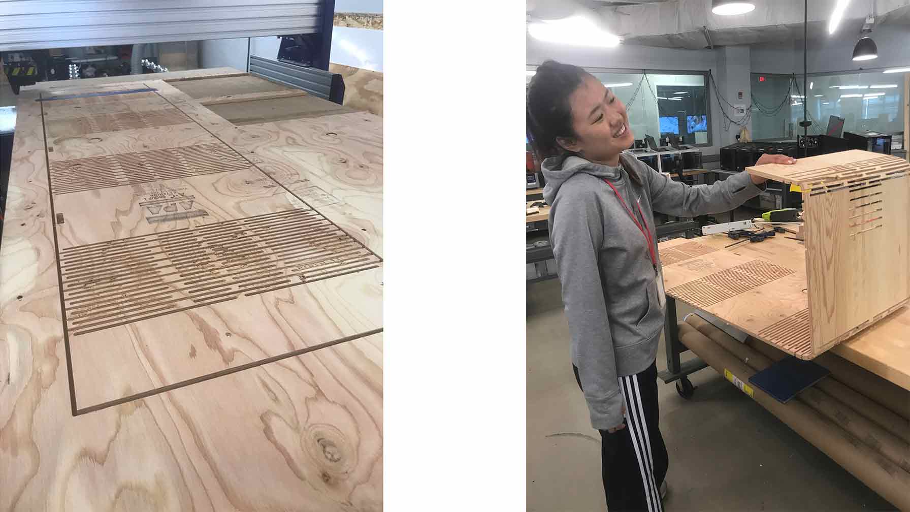
I ended up making the cuts futher apart and using a scrap piece of ply that was higher quality. I had to change every single file in my design.
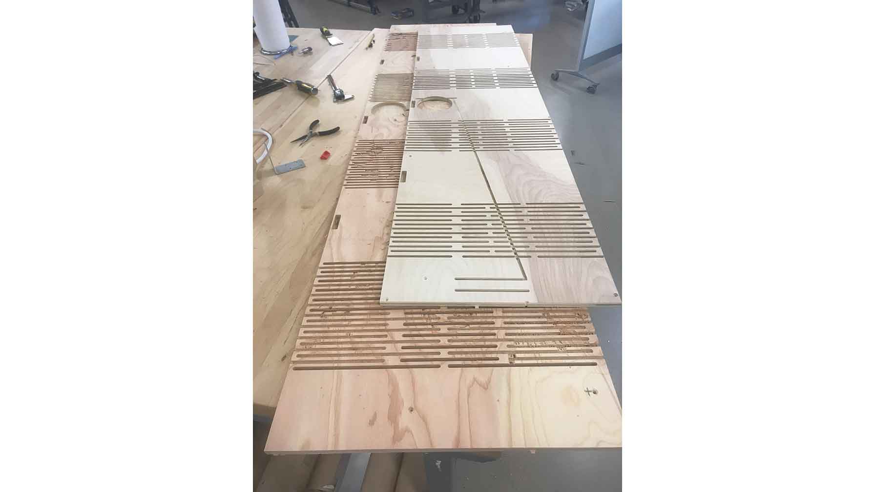
You can make out some of the differences here.
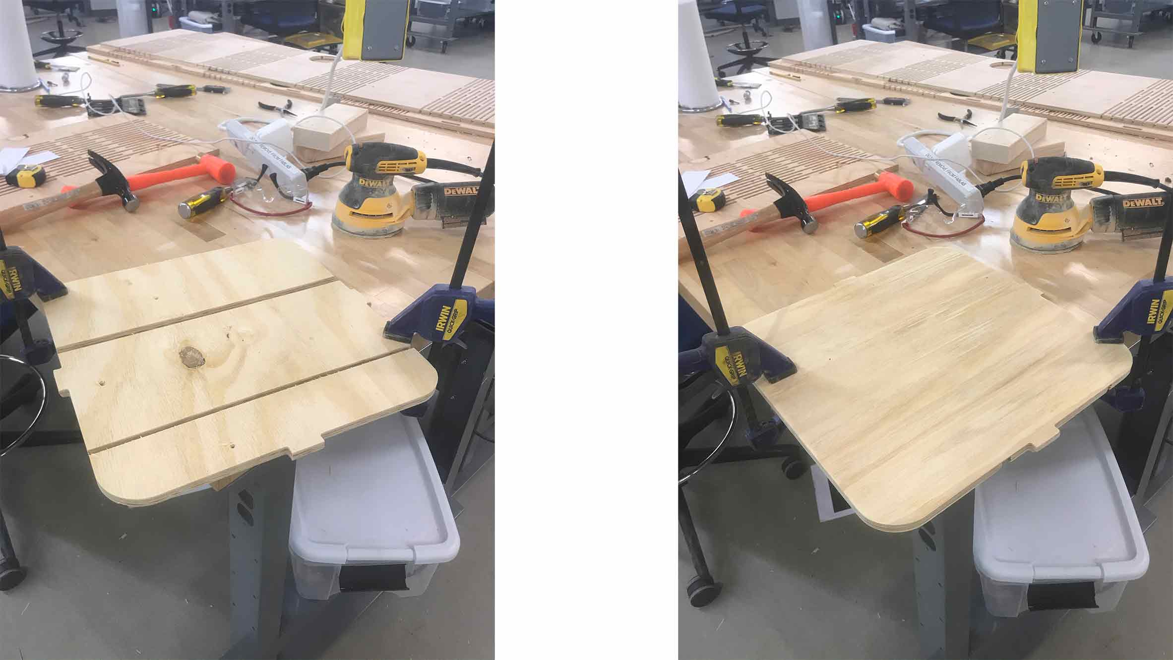
This is supposed to be the back profile with insets for shelves and tabs to fit into the long perimeter piece.
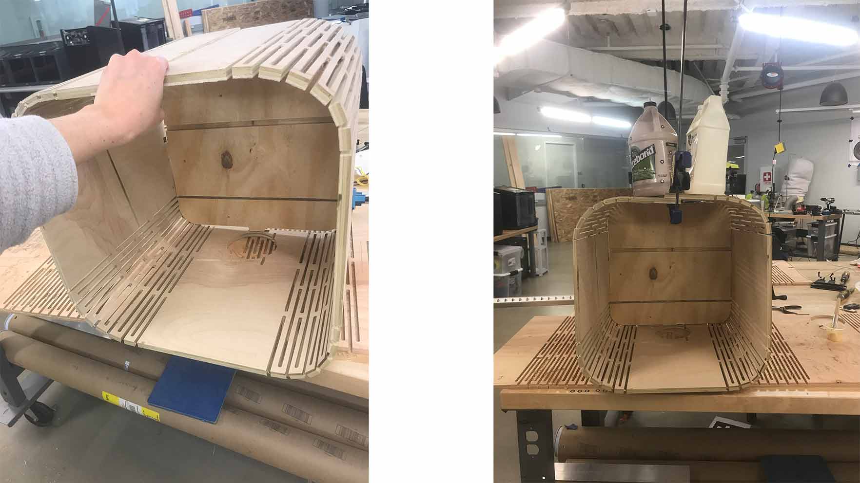
When I started to wrap it around the rear profile piece there was alot of cracking which worried me but nothing fully snapped. I intentionally left some extra at the end becasue I didn't have confidence in my math abilities...? And I used heavy containers of glue to hold it down while I ran to find clamps.
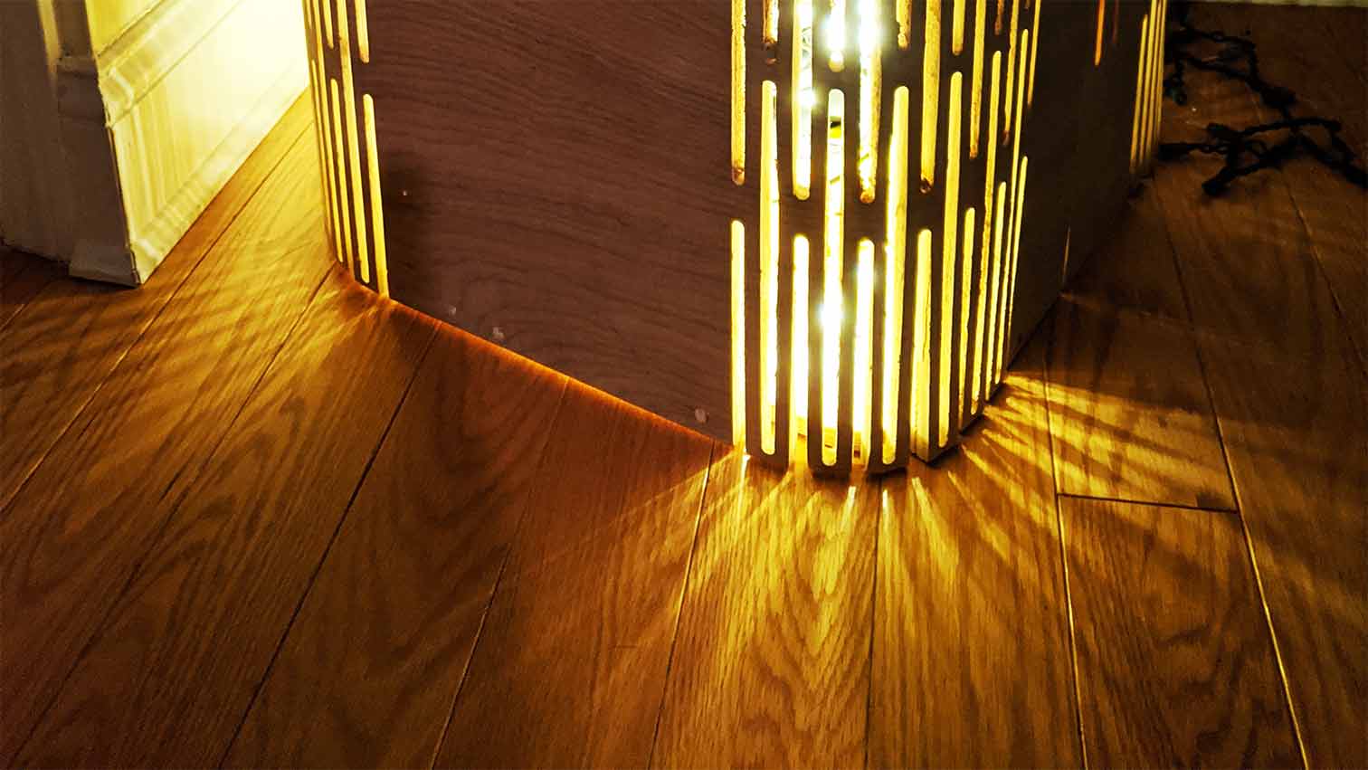
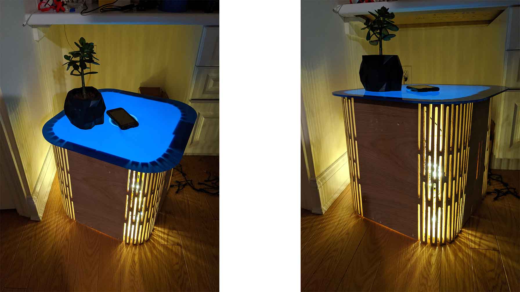
At this point, many things were not going well. It needed pressure from so many different angles and it was very hard to make all the angles 90 degrees. Also, I didn't really account for how long the kers would be and mounting hardware for the drawers seemed unlikely. So I pivoted and kind of played with the idea of making it so that it at least achieved some of the original functionality I had hoped for. This ended up being, a hidden chi charging station, a piece of functional furniture you could put stuff on top of, and a light. While these utilties did not manifest in the original was I had intended, I made it work.
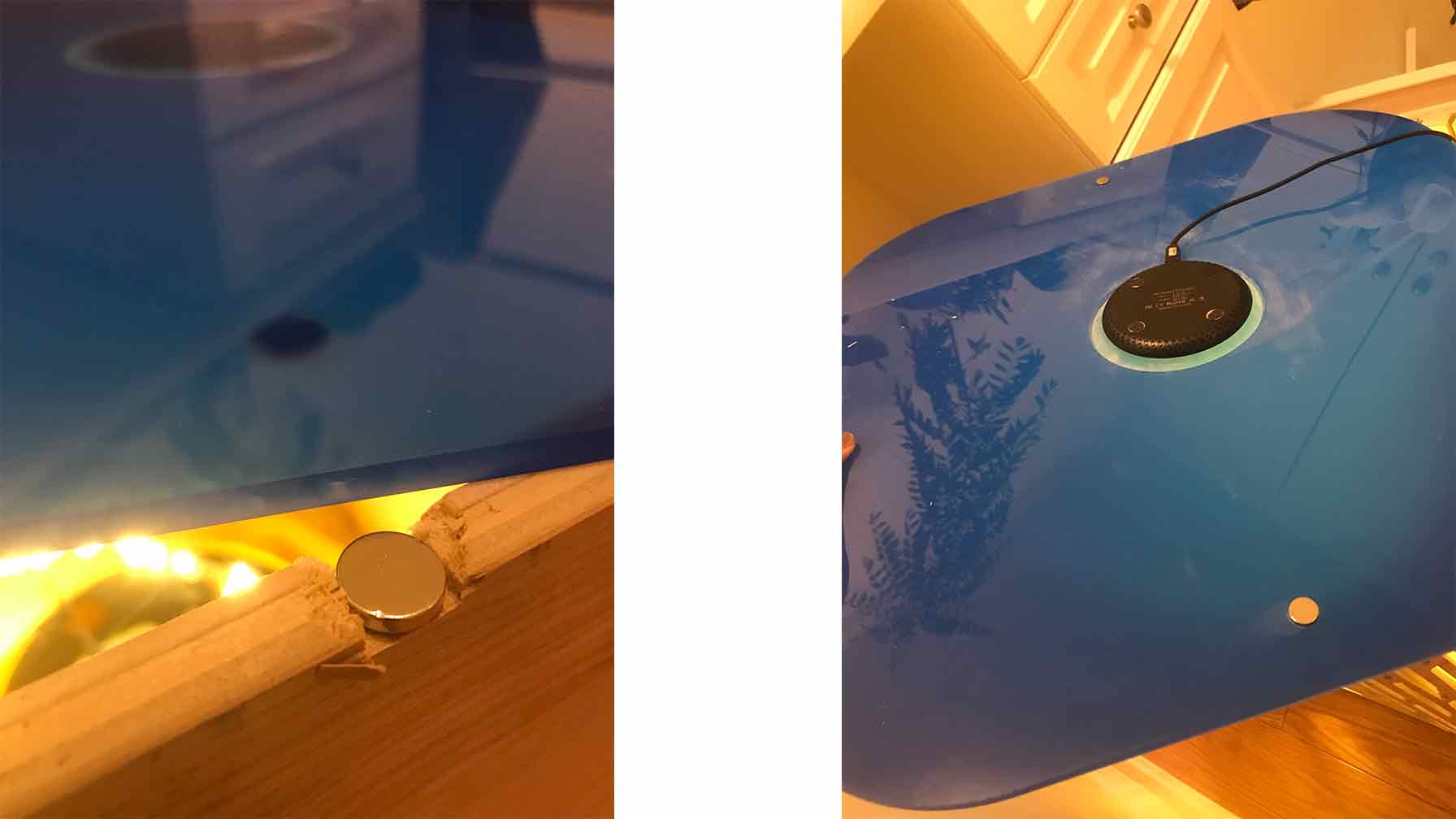
I laser cut a piece of blue acrylic for the new top and rastered the spots where I needed magnets and the charger. The charger can't go through material past a certain thickness. So this was very trial and error.
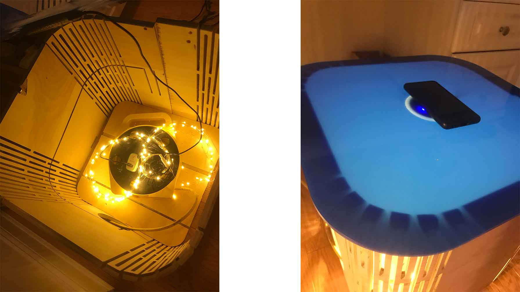
Then I found a bunch of random stringed lights and stuck them in there.
WHEW!!!! I'm going to bed.