Notes from Greg's Lesson
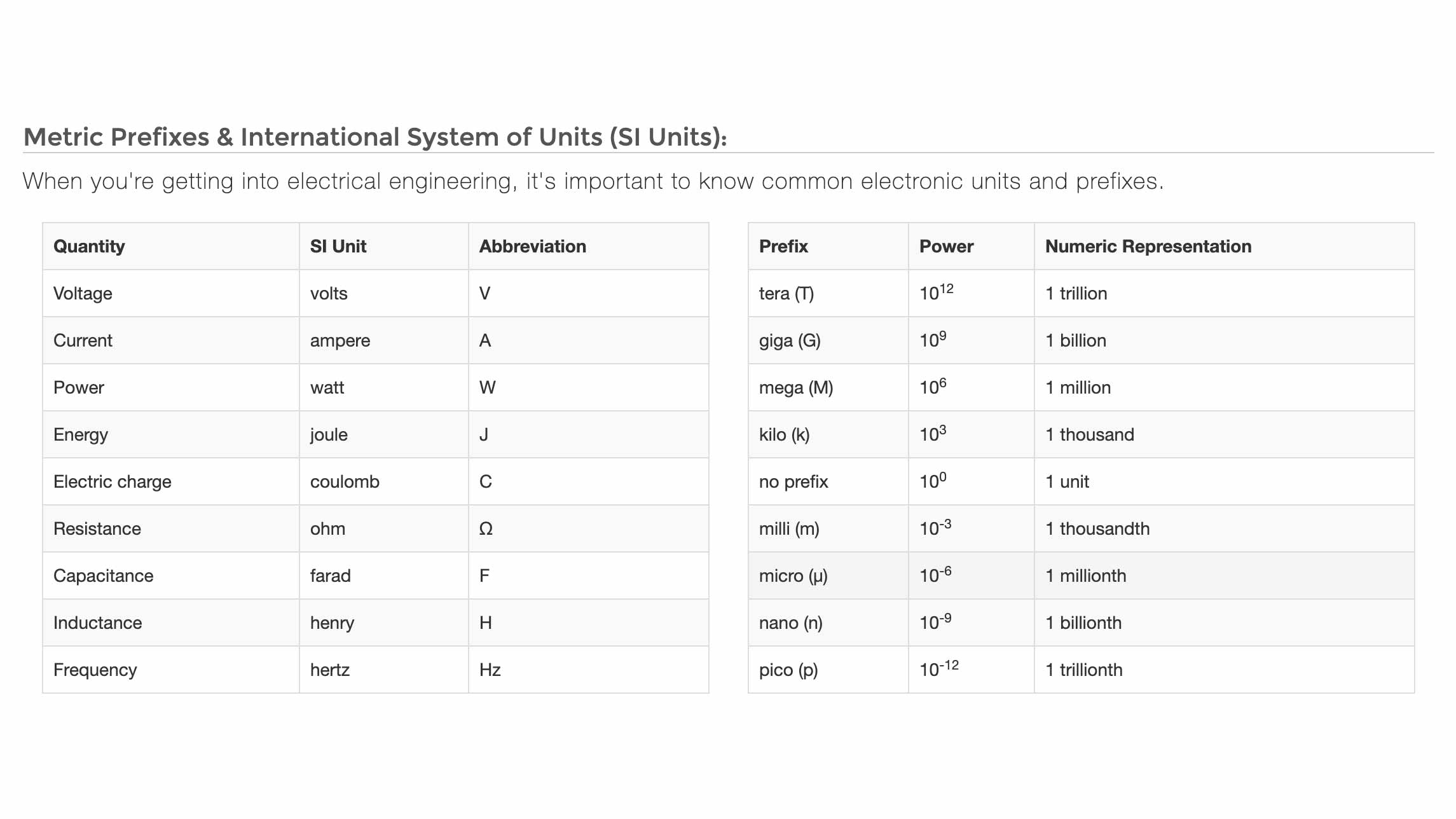
To start, I have never taken a physics class and I think I made below a C on most of my high school math classes. I definetly feel behind compared to my other classmates. So to begin this week, I think it's important for me to go over some basics. Greg helped with this using water as a way to explain many terms and processes; Water = Charge, Pressure = Voltage, and Flow = Current, Hose Width = Resistance. Following others advice, I checked out Spark Fun which also uses the water analogy. Also, they break everything down into easier modules that make learning this easier. So for my sake, I'm going to go over some basic vocab that's been used alot and I assume I'll need to understand. Most of these photos are from the Spark Fun tutorials that I sited above.
Electronics 101

What is voltage?
Electricity is the movement of electrons and voltage is an expression of that... voltage is the difference between two points in a circuit
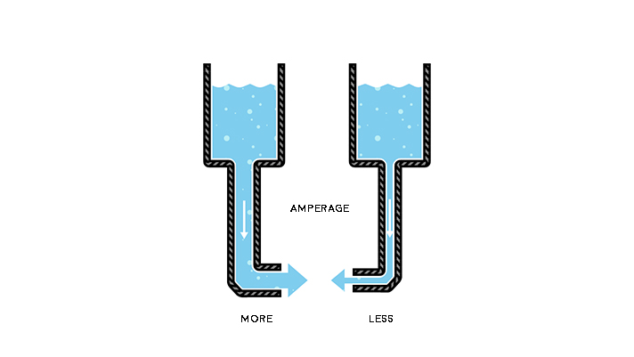
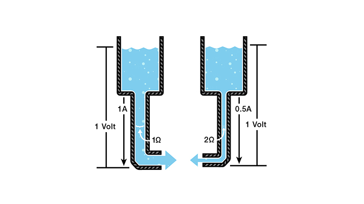
What is current?
Current is measured in Amperes (usually just referred to as "Amps") and is represented as an I in equations. On the left, the tube is bigger and on the right it is smaller. More water is running through the one on the right; higher current.
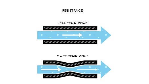
What is resistance?
Resistance is kind of like how much water can get through the tube... or how much charge can go through something at once. This brings us to Georg Ohm's Law called Ohm's Law. In equations, Ohms looks like the Lululemon logo, Ω. Voltage = Current x Resistance
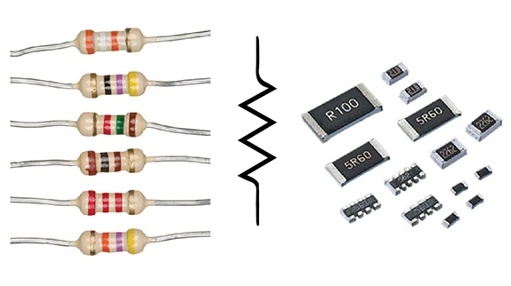
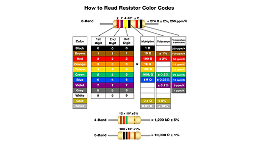
Resistors...
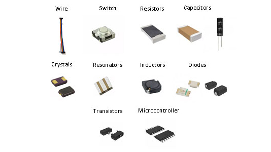
This is what some resistors look like. There are lots of different kinds of resistors. We use SMD (surface mounted devices) resistors. Different kinds of resistors have different ways of knowing what they are. This guide helped me better understand the ones we have been using in FabAcademy. Also the zig zag line is how they look in some diagrams.
Ohm's at Work
V = Voltage in volts, I = Current in amps, R = Resistance in ohms
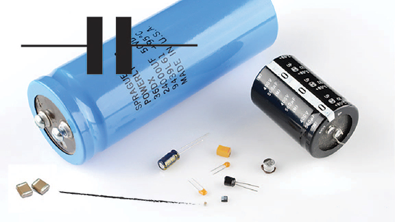
Capacitors?
The basic function of a capacitor is to store electrical energy. Essentially, potential difference is created and that translates into energy until it is balanced out. When you add electrical energy to a capacitor is is called charging and when you release it it's called discharging. We measure capacitance using farads.
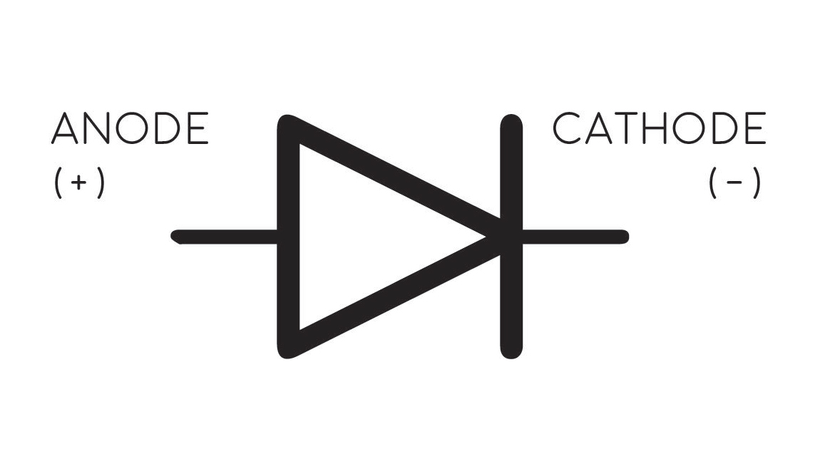
What are diodes?
Diodes have two terminals and they are distinctly polarized. Diodes kind of help current go the way we want it to I think...? LEDs are light emitting diodes.
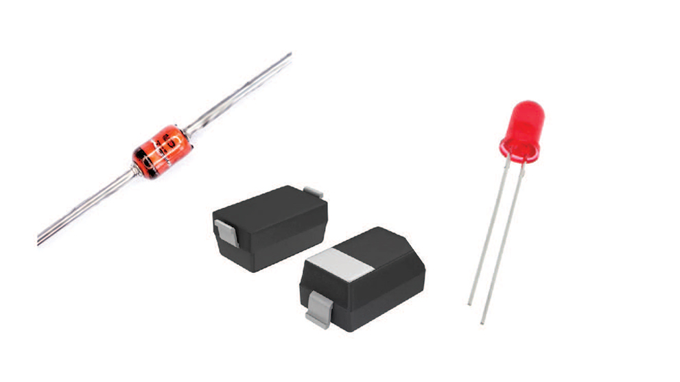
Zener diodes and LEDs
For the ATtiny we did last week, we used two zener diodes and two LEDs.
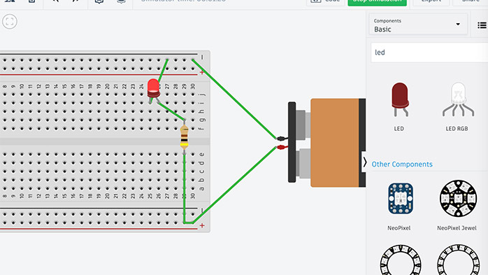
Using Tinkercad to simulate how these components functionwas SO helpful. This seems really elementary but was a very helpful learning tool for me. This is part of the reason I understand why resisotrs aren't polarized.
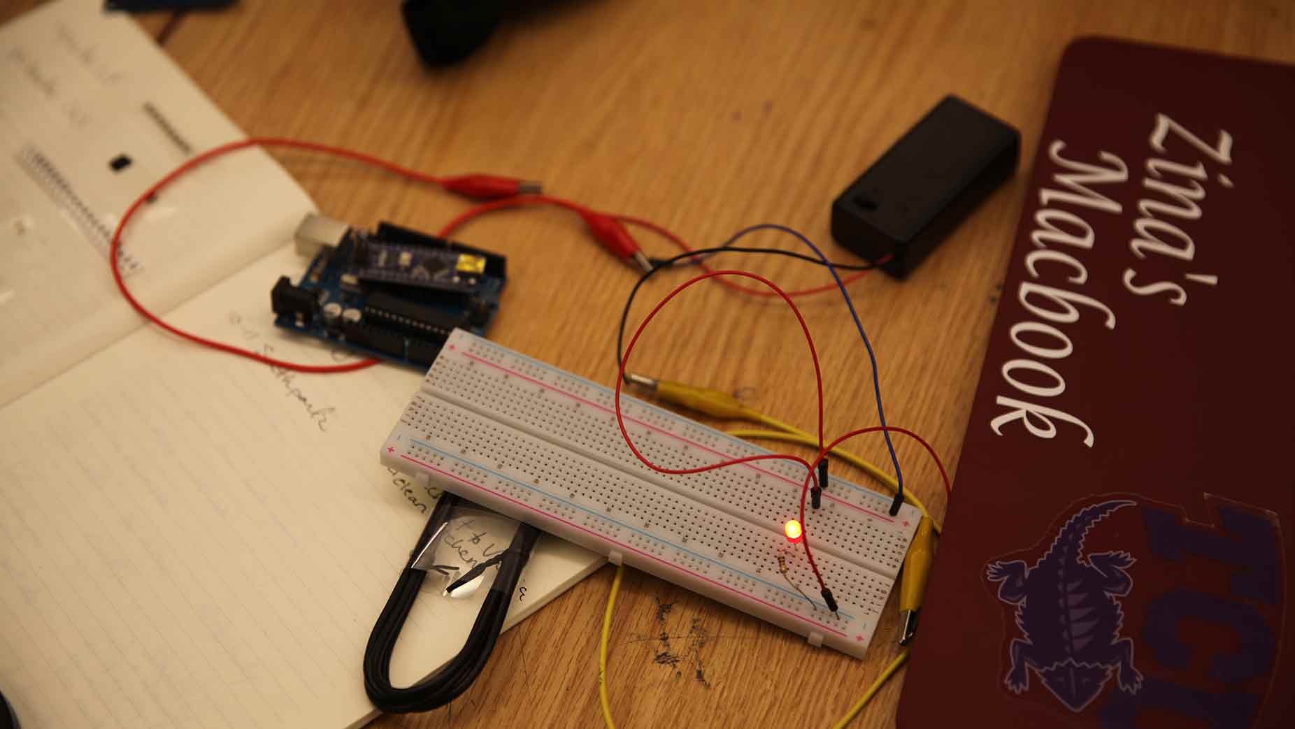
At this point, I just wanted to try out what I had done in Tinkercad... pretty cool. Also... I got hungry thinking of bread...
Designing the Board
So the board I am trying to make will have a button and a light that is turned on and off by the button. Sounds super easy, right. Lies. To get started, because I was already using SparkFun, I continued with their tutorials and started cross referencing them with the FabAcademy one. I downloaded Eagle and then saved this schematic to my Eagle projects.
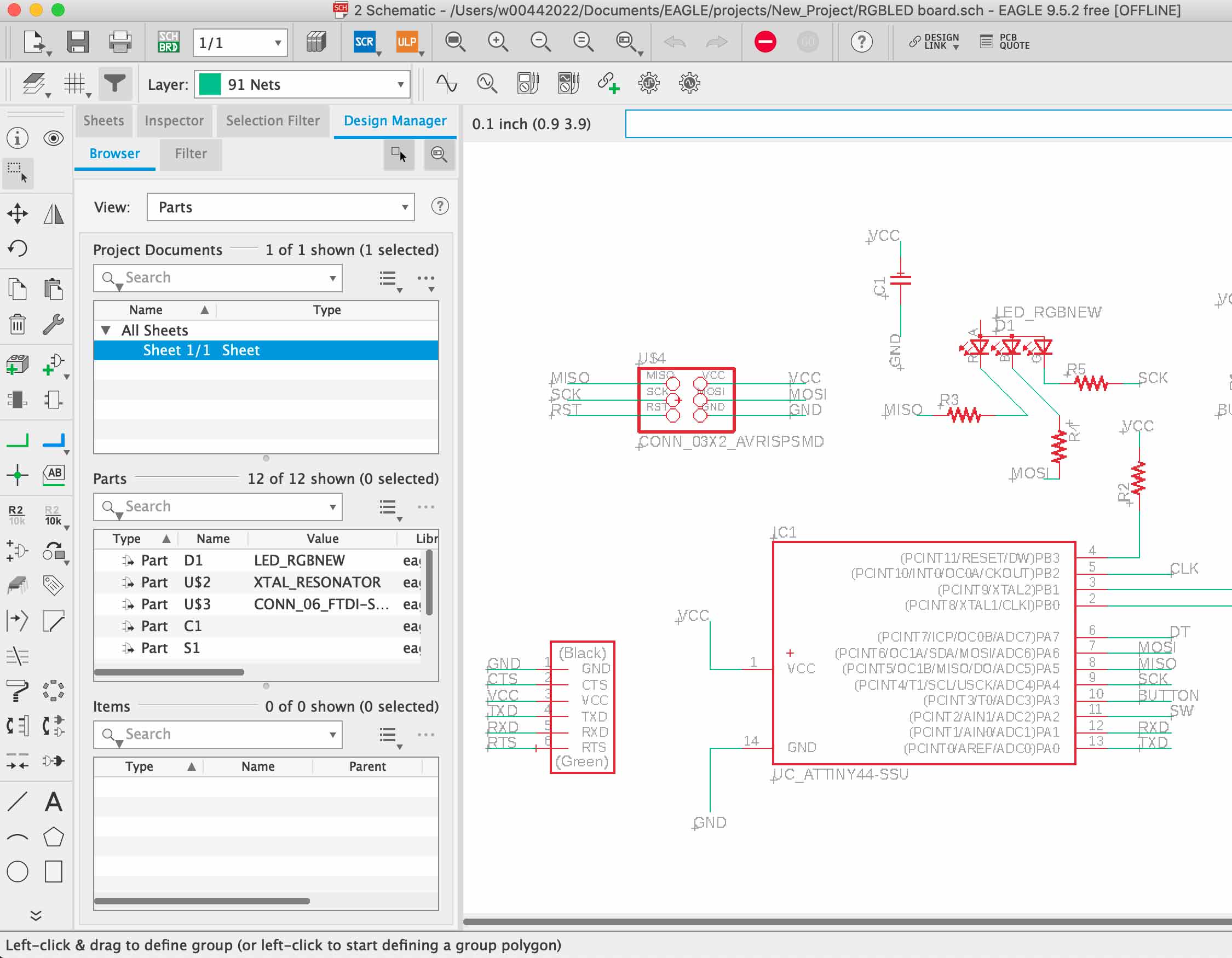
Diving into Eagle! This is generally what Eagle looks like and I will go into more detail in the future weeks.
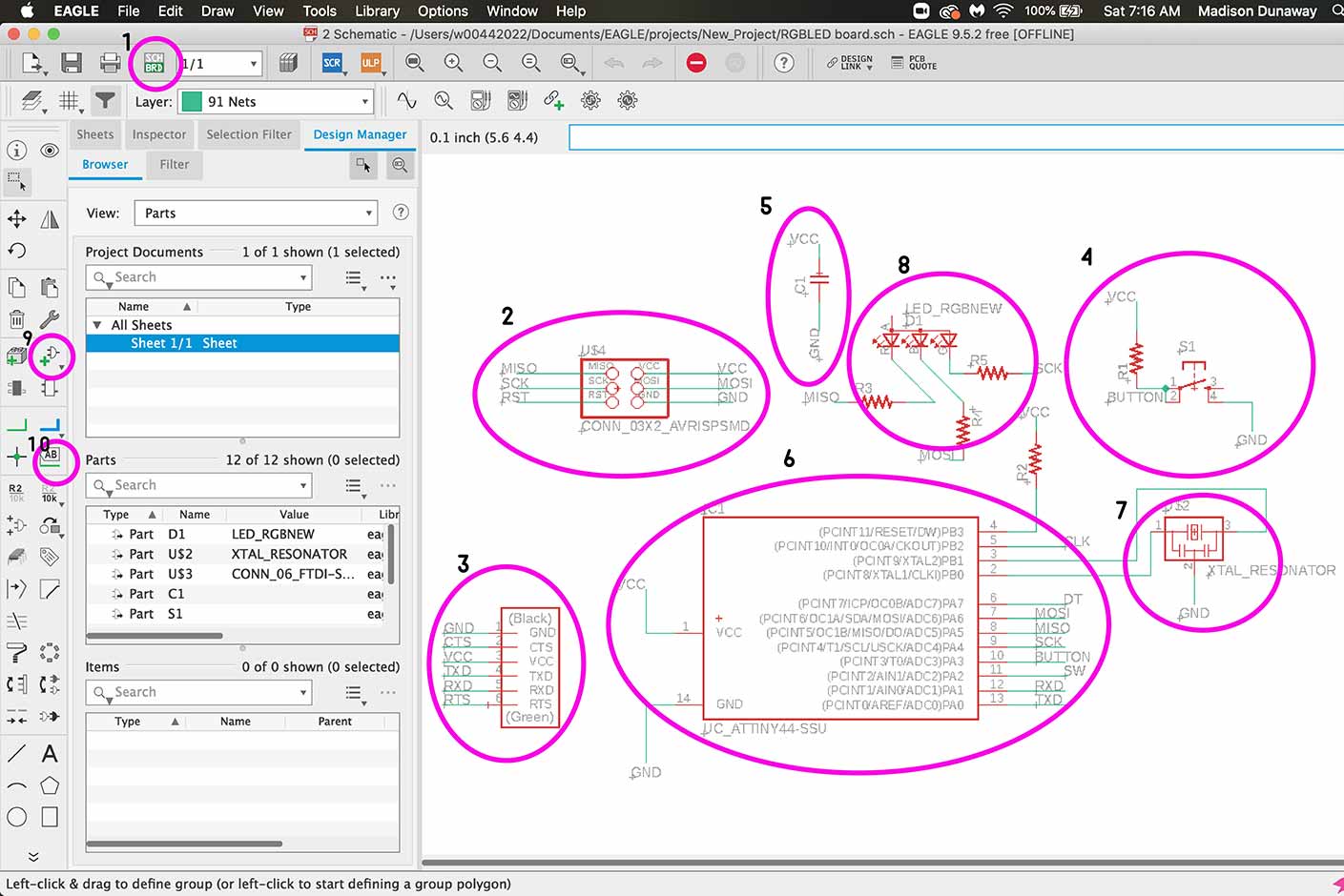
Let's go over some Eagle stuff from a future week here.
- This is how you switch back and forth between the board and the schematic.
- This is the ISP connector which is how you will initially program your board.
- This is the 6 pin header.
- This is the button.
- This is a capacitor.
- ATTiny44
- Crystal Resonator
- RGB LED
- How to add a part
- How to label and therefore connect a part.
Closed and open circuits - Electricy is the flow of electrons... and there are lots of tricky traits to understand. How much water is going through a thing... is kind of like volts. Current is the flowrate of electrons... how much current is being forced thorugh a pipe... Current is meseaured in Amperes or Amps. Thes size of our pipe... can be kind of thought of as resistance which is measured in Ohms (r). More resistance means smaller pipe.
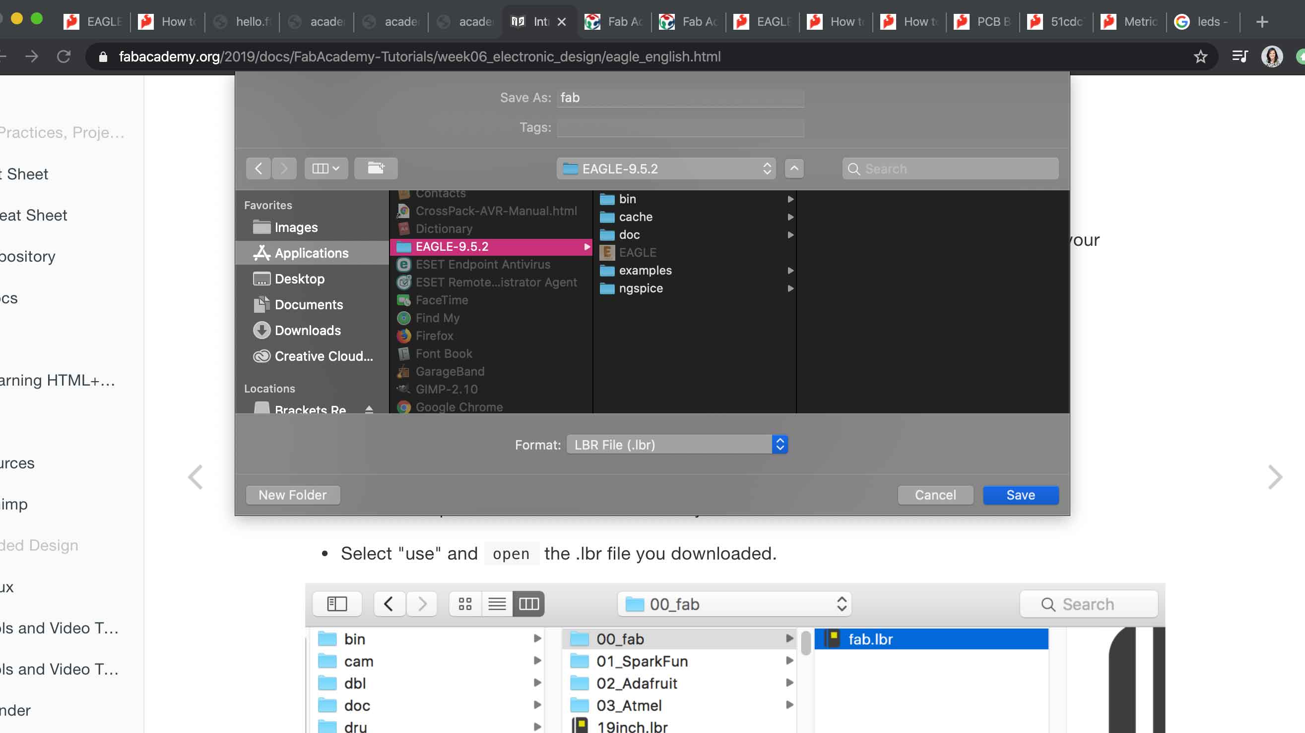
Installing the library.
Already installed the schematic and this is me installing the library.
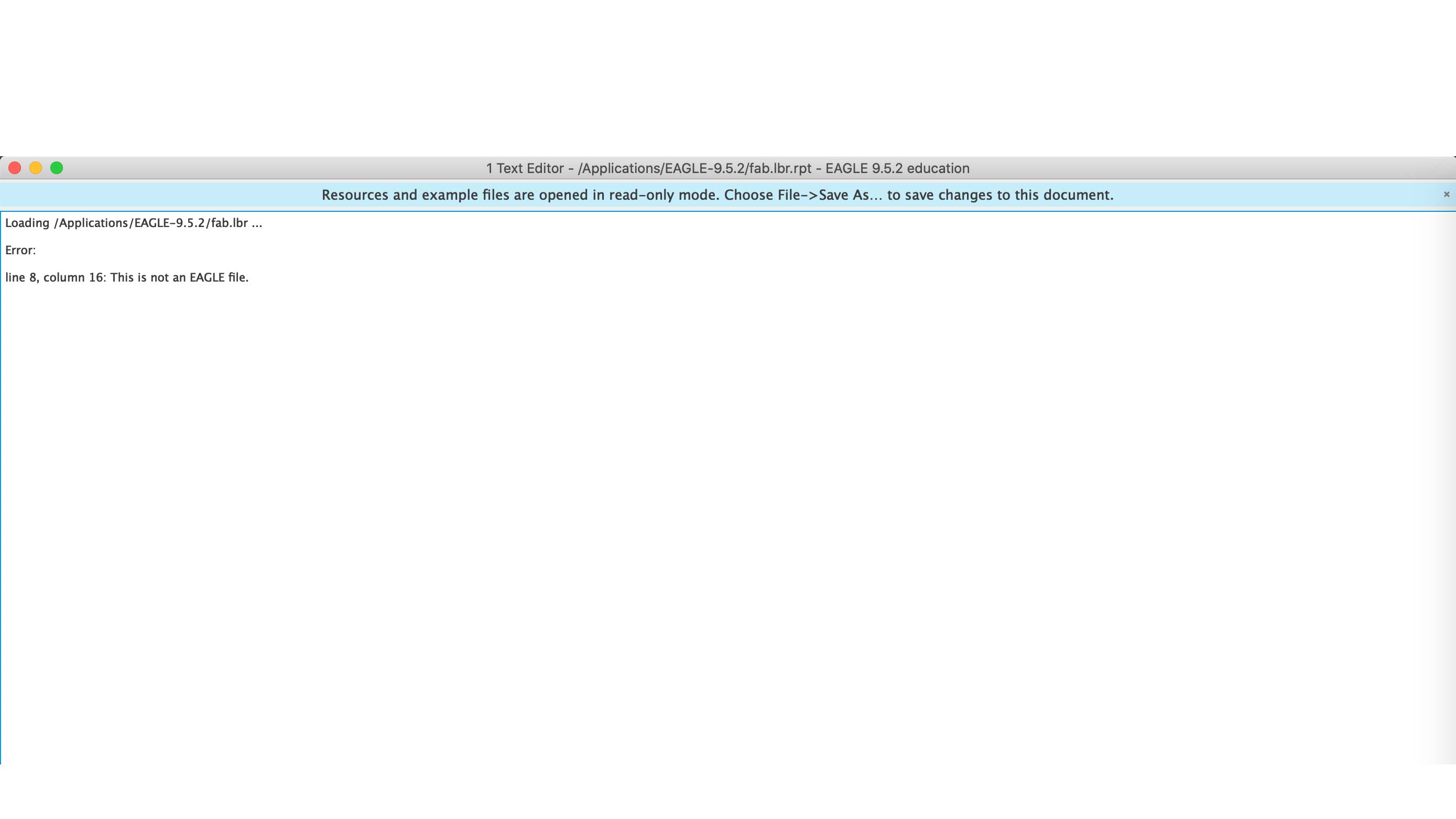
Error message
When I tried to open it, this is the error message I got.
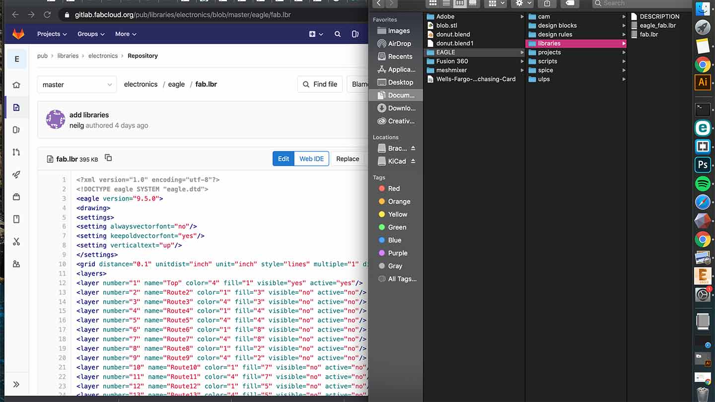
Copied from GitLab
I ended up downloading it from GitLab and that worked. I think I originally had it in the wrong place.
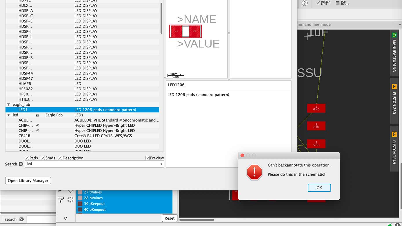
Trying to add the LED
I used the command line to add the LED and kept getting this error message.
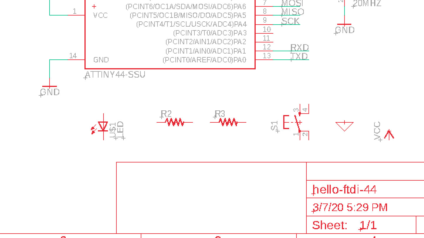
Added the components
I just put them in a line...
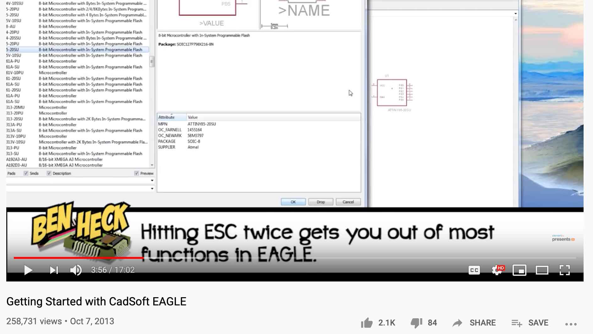
Video
While watching this video I found in the depths of Youtube, I tried hitting esc twice t get out of adding and it worked... which was great since I was just going back to the lib and cancelling.
Info Button
I found the info button which tells you about the component you are clicking. This helped with nameing in my schematic.
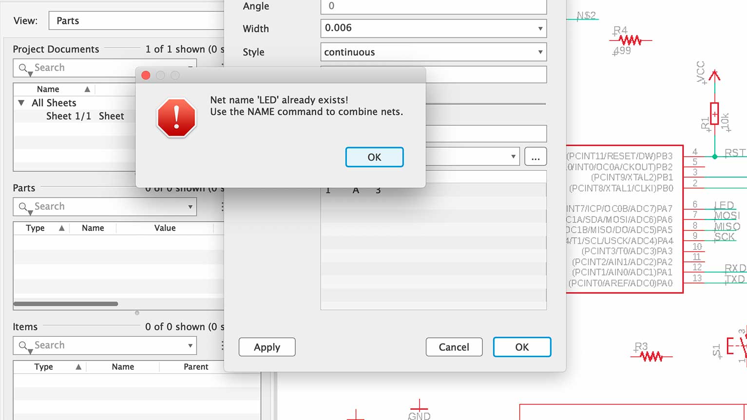
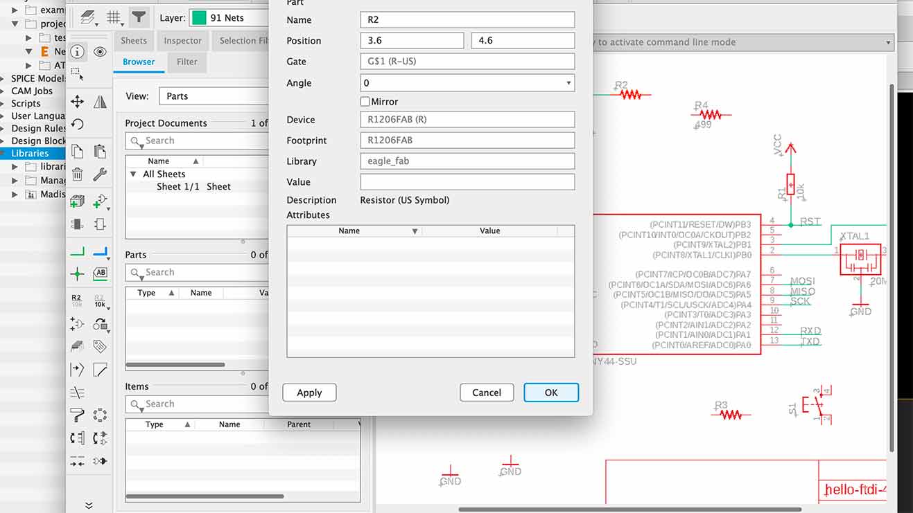
Nameing
I needed to use the command NAME.
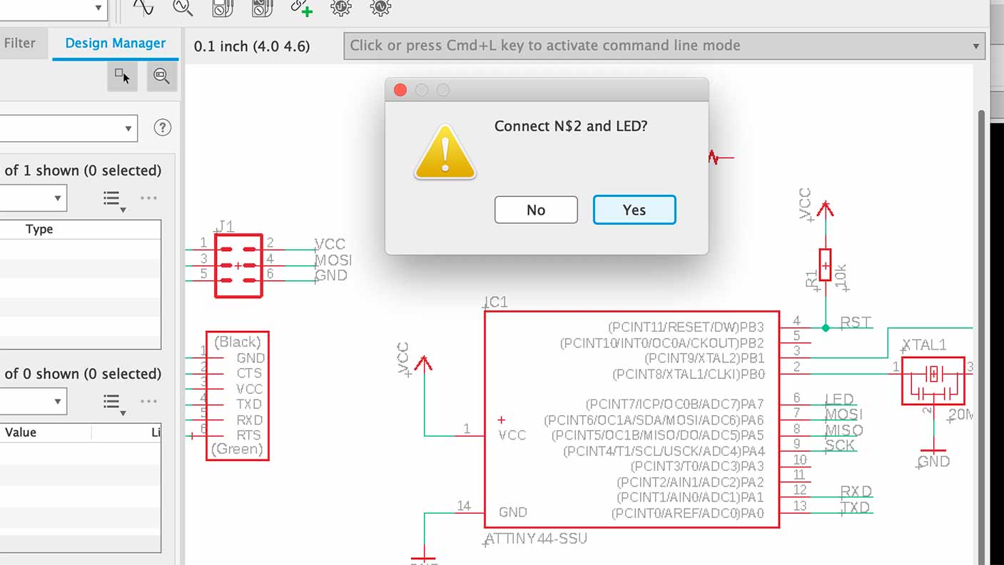
Connect
I got them to connect and be in the same net.
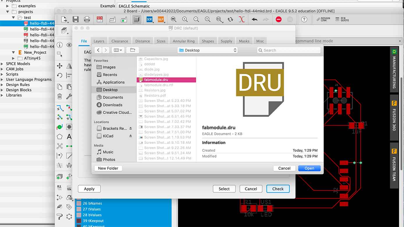
Importing the Design Rules Check
I found that script here.
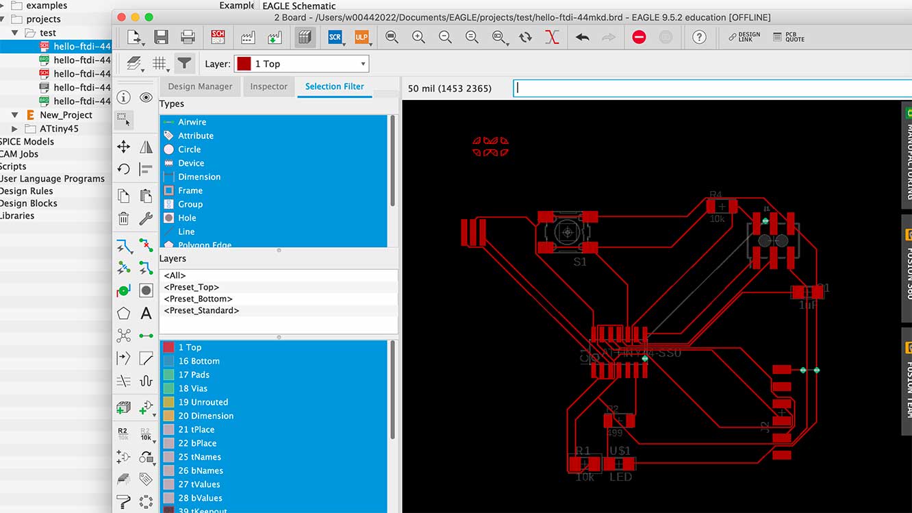
Using the Autorouter
This is one of the first times I used the autorouter. It assumed I had a souble sided board which is what I think those green circles are.
Messed up Traces
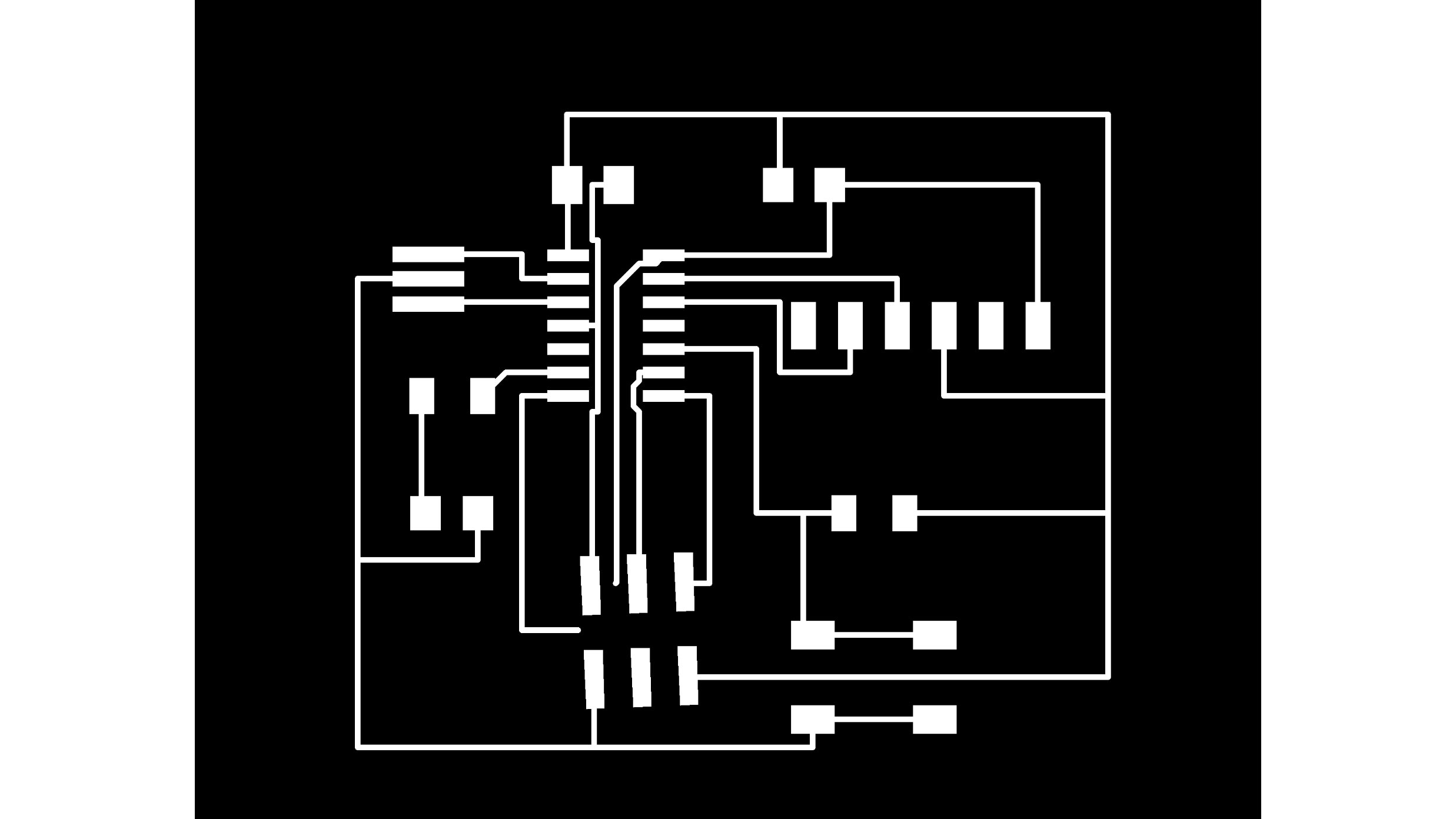
Becuase I was not using the correct 2x3 pin header, my lines wouldn't connect. I was kinda fed up so I brought them into Ai to edit.
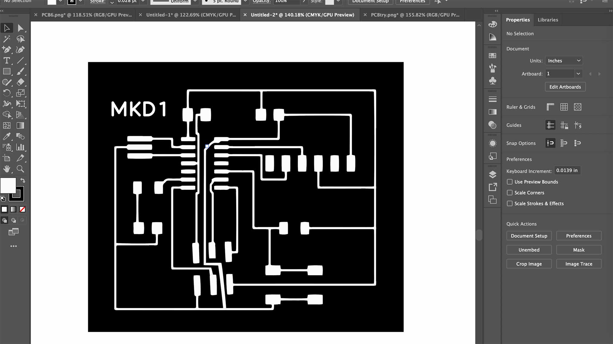
Ai Post Editing
This seemed ok so I went to mill it.
What is a resistor? We need resistors but how do we choose the right one? Ohms Law Components V Power Source R=(power source 9v - forward v - how much it needs) / fast current moves which is amps.
Helpful diagram even though this isn't what we use.
Yikes
Eagle is insane and I hate it with a vigor... except for the part where I got to connect everything by hand and that was slighlty therapeutic. If you would like a migraine to ensue, feel free to look through these photos which represents my day starting at 7AM and ended at... oh wait it still hasn't ended. Also, shout out to Greg for helping me every 30 min... I don't think I've developed the grit to fully work through all of this myself.
So this one was way too big and I didn't realize it until it got started. It's hard to see here but it was basically 2" x 2" which I didn't realize was not right. I later found out from Greg that whats was happening was an issue with my Mac. Apparently exporting form Macs wasn't working and I needed to export from a Windows or Linux... which was a yikes since I didn't have that kind of computer. I ended up borrowing one and re did the whole thing.
As you can see, it took up quite a bit of space so I stopped it.
The router lines I made in Eagle were too small and they needed to be 12.
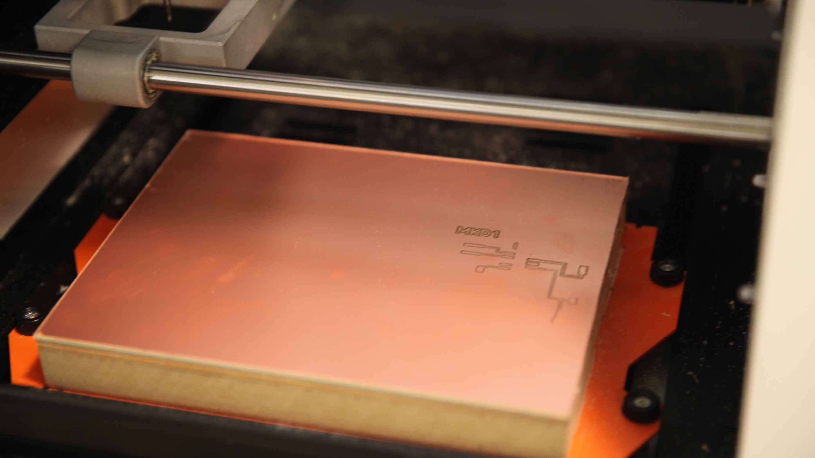
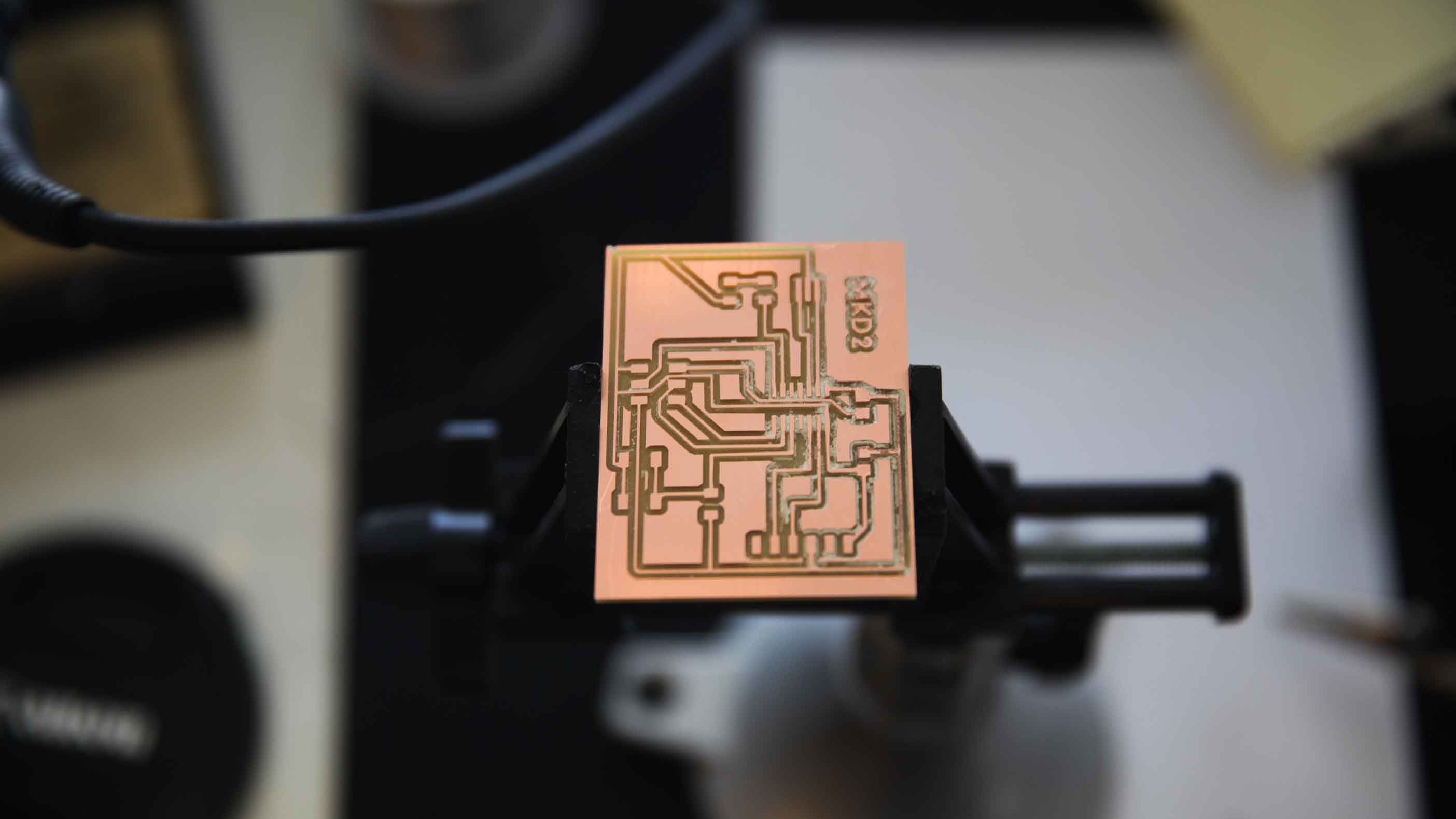
After the entire redesign on a Windows, I tried milling it again and it worked.
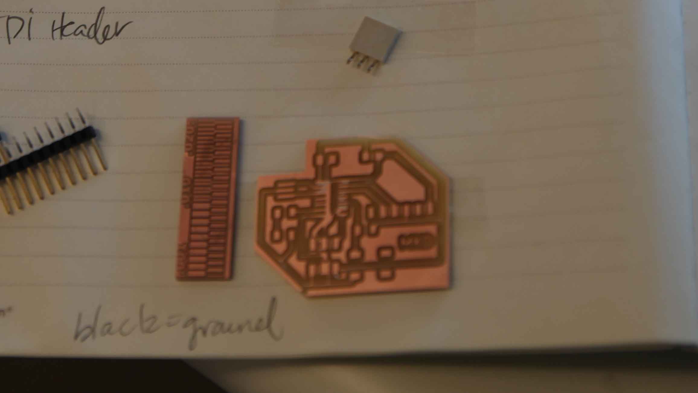
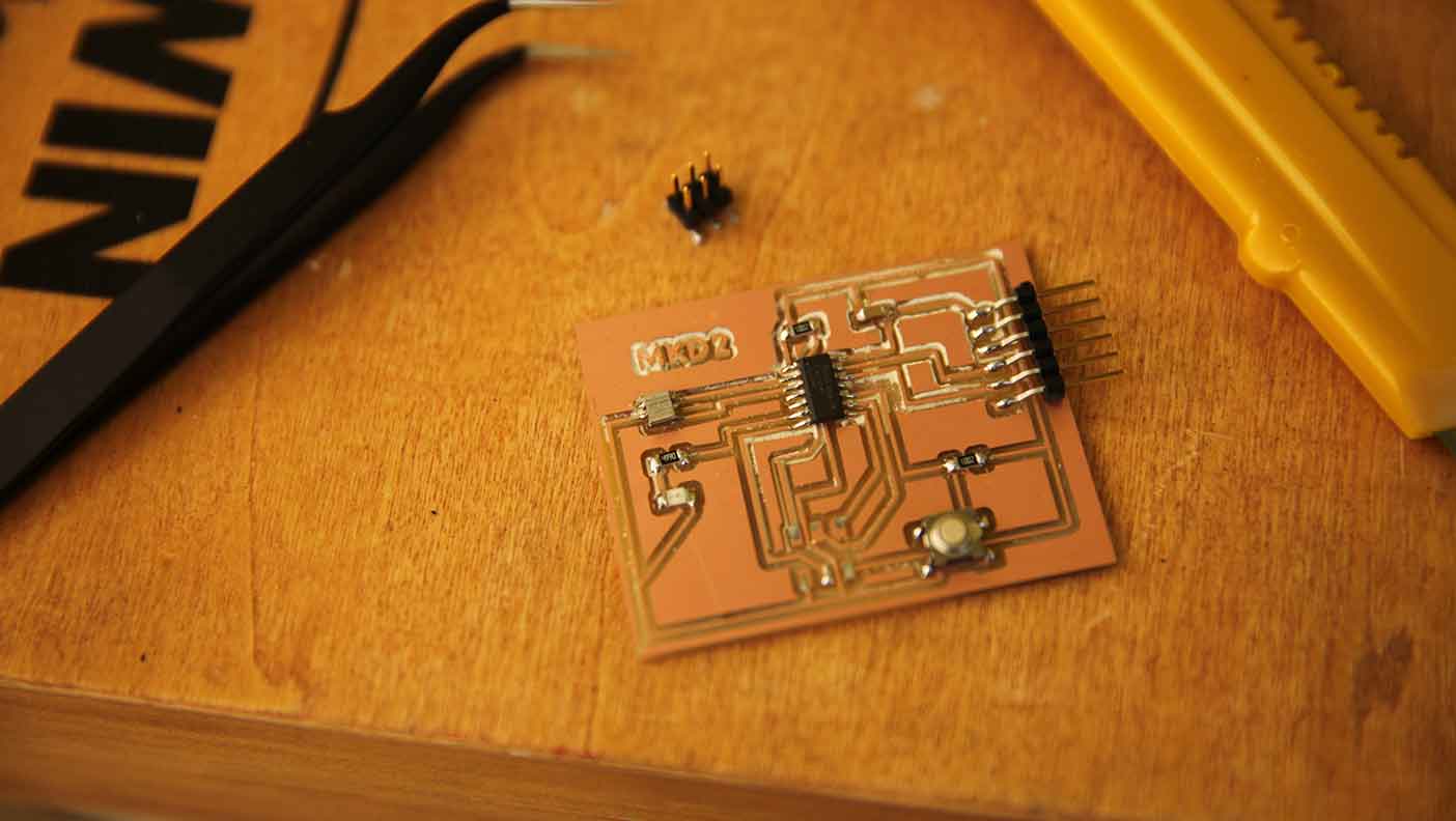
I wondered why we wern't using a reuglar CNC and Greg explained it's because PCB mills have micron level precision. We then cut the board out and Greg began to show us how to solder and collect our parts.
I was stoked. The trace cut too deep... but I went with it.
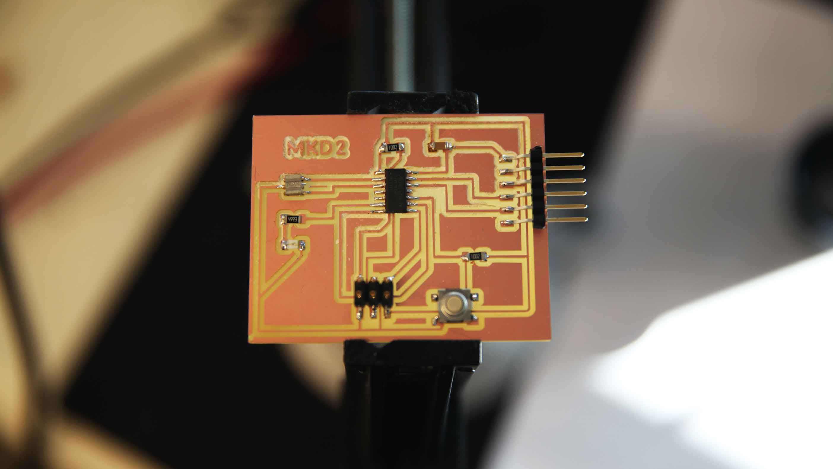
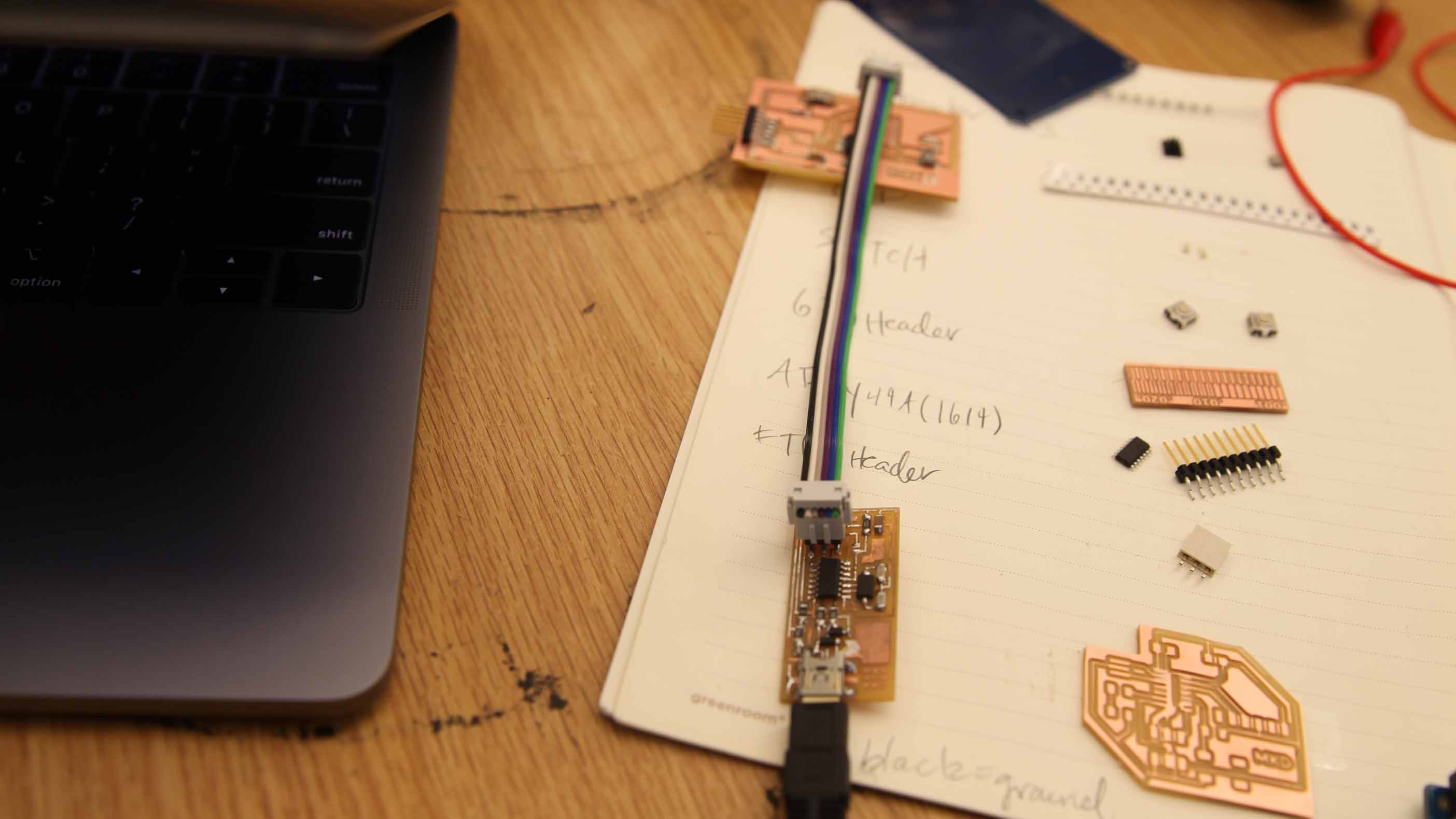
Then I found the right components and soldered them... trying to make those catenary solders like we are supposed to.
Programming Begins...
This is where I started getting even more lost. I ended up going to Lena Park where our FabAcademy teacher works to get help. Starting now, the journey I took may get a bit convuluted, poorly documented, and confusing so I'm going to do my best to list the sites I am learning from. This tutorial is the first one. From there, I jumped to Saba Ghole's site who was a 2018 student and has in depth documentation. Thanks Saba! I impulsively downloaded Arduino and then dove into High Low Tech's tutorial. I soon realized I needed to add a new board... right?
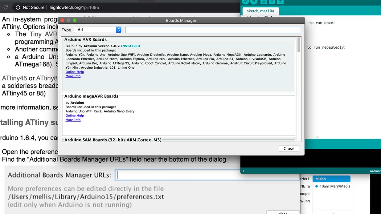
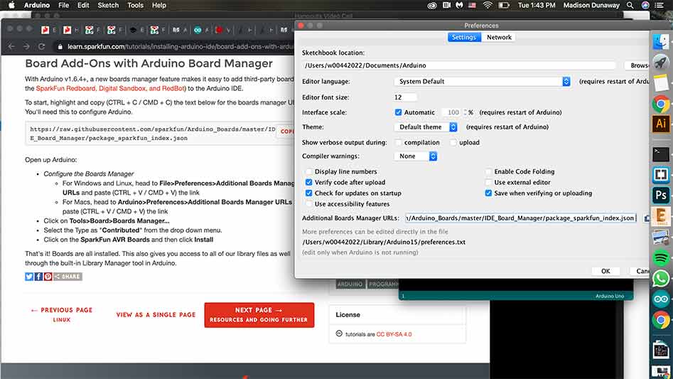
That link was really helpful. I needed to go to preferences first.
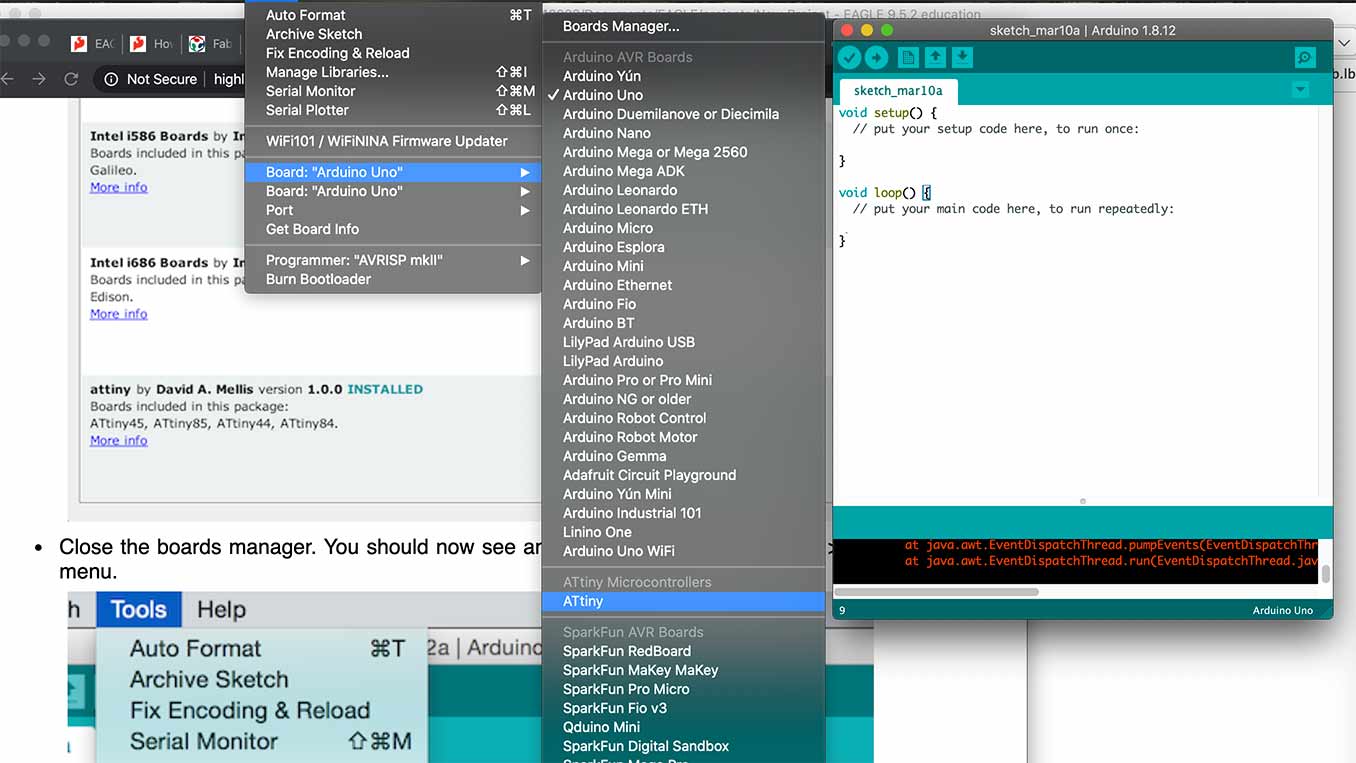
Now ATtiny shows up in the dropdown menu which I think (emphasize the I think) was the goal.
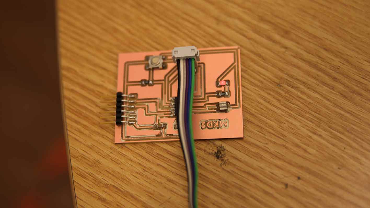
This was all going great until i realized I didn't have a USB port on my mac and no dongle to use to hook it up.
This it what I needed a USB port for.
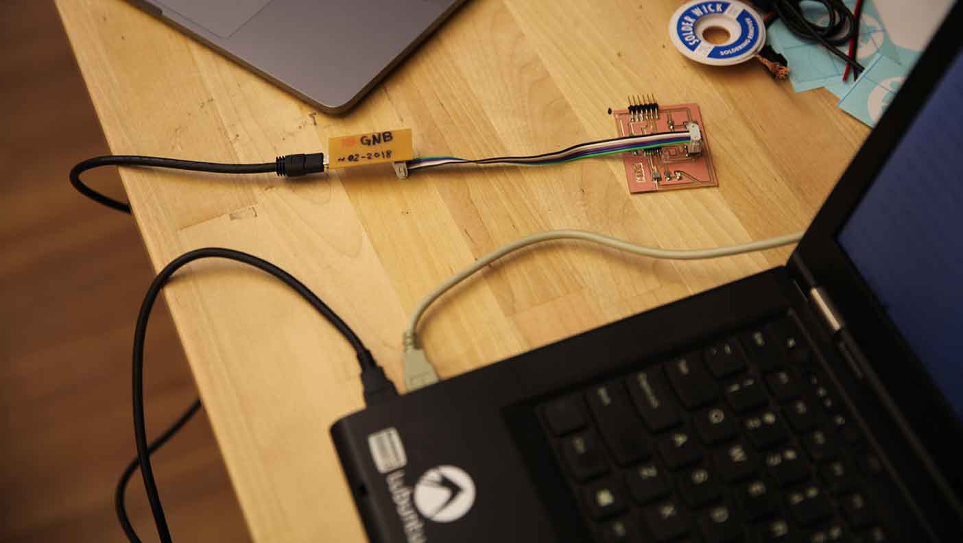
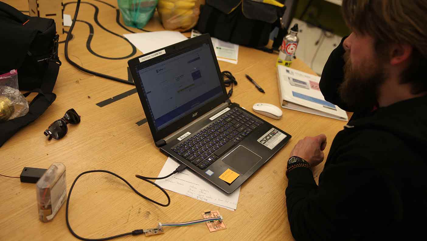
This is Greg's linux computer that uses Ubuntu. This interface was totally new to me and a bit confusing at first.
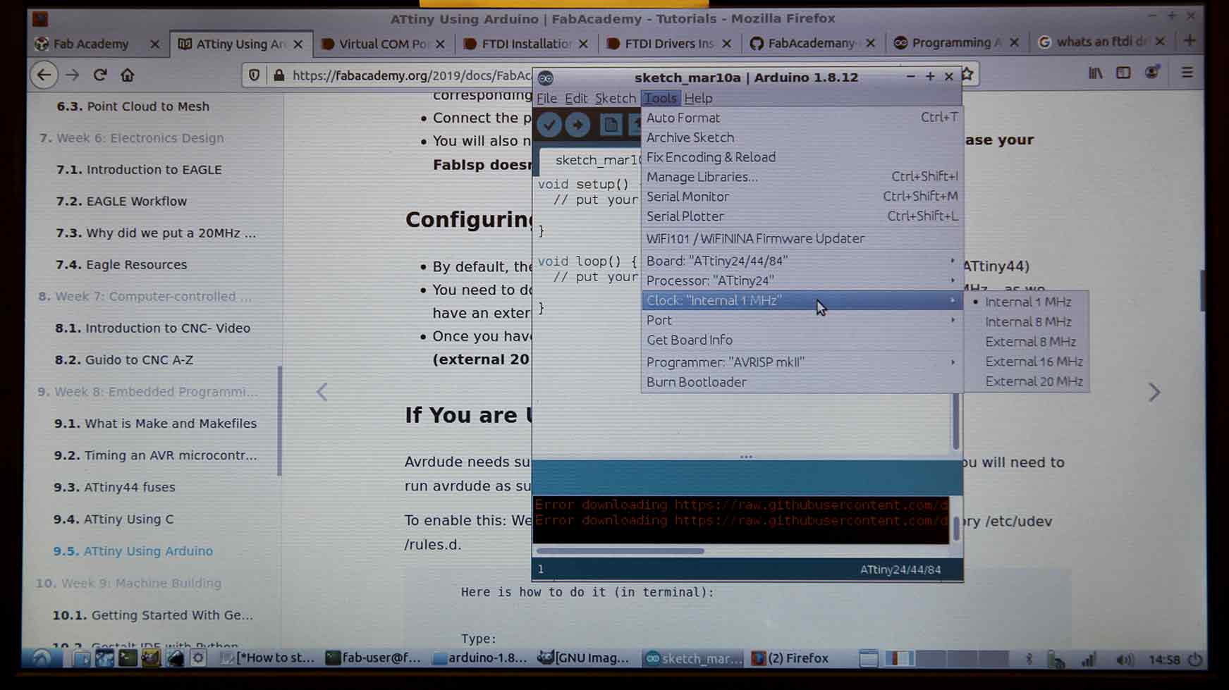
I started getting the Arduino software side of things set up which meant changing three-ish things: the board, processor, and the clock.
Then the problems began. I should say the next round of problems which at the moment felt like unsolvable nightmares but in retrospect were totally approachable given the right context and information.
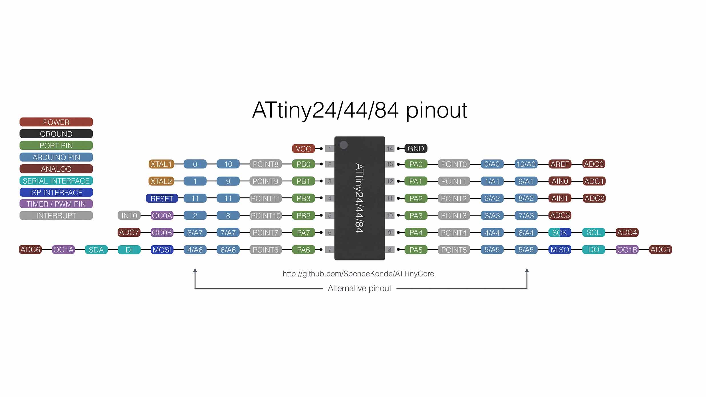
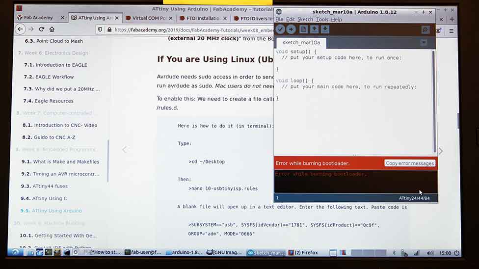
Even though the "Burn Bootloader" command wasn't working, I kept going. I needed this diagram to unserstand how my pins related to the Arduino software we were using.
I tried to upload my code but that didn't work so we tried the next thing. We thought we could try it on another computer to see if it was my board or Greg's computer.
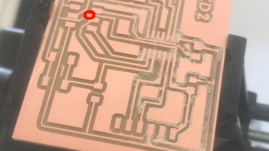
It was my board. Greg remembered at one point my peer Nicolas said it look like something was mistakingly connected... which it turned out it was! Thanks for catching that everyone!! :D
I used a heatgun to remove the 2x3 pin header. I then used a utility knife to remove the conductive copper that was causng the problem. Basically a tiny connection that wasn;t meant to be there but the mill didn't remove.
Then I plugged it in and it lit up!!!!! AHHHHHH!!!!! I thought I was going to cry. This was the reason I existed for the past 48 hours. I continued to learn about how to make these in future weeks and it's always a learning process and takes me time.
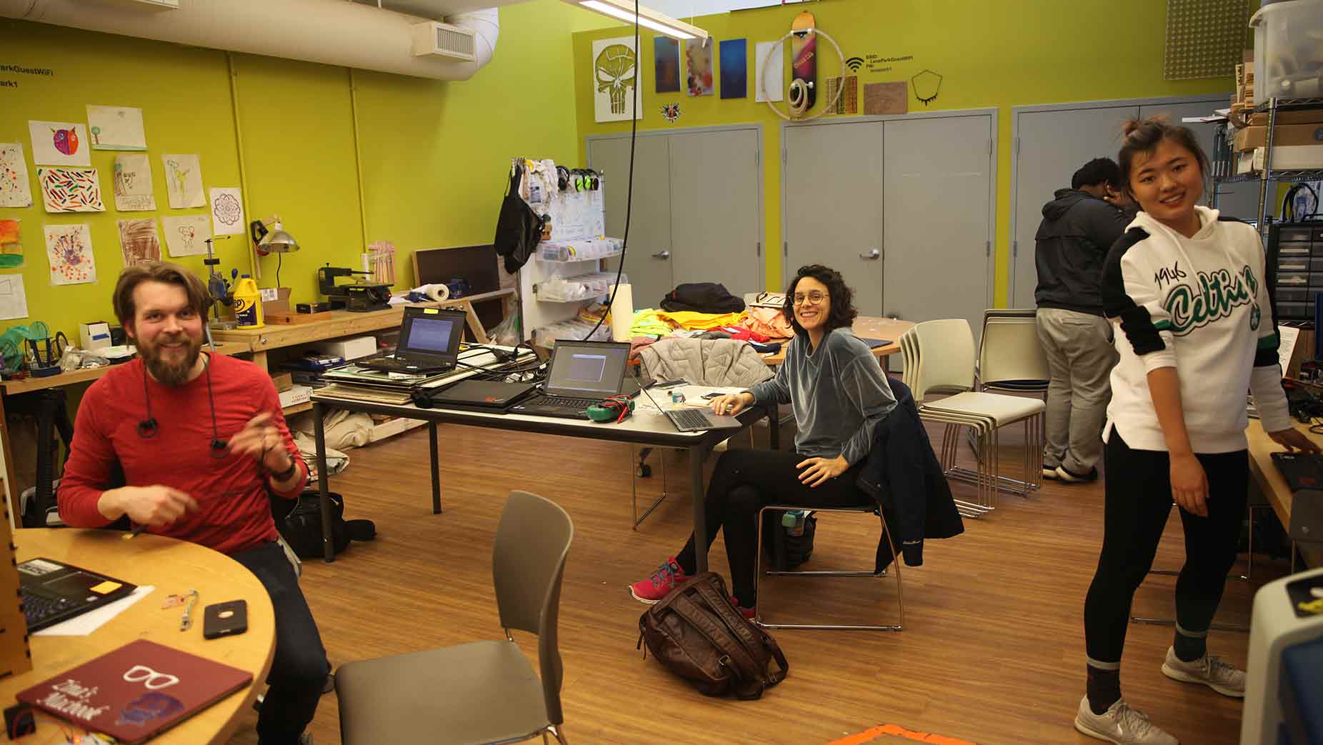
This is a photo of the lab at Lena Park Community Center. On the left is Greg, middle Martina, and right Zina. Pretty cool that these four people are doing this.
So, at the end of the day... it didn't work in the intended way. As Greg said, this works like a car still goes downhill with no breaks... the sbutton does turn the light off but not because I programmed it... actually we aren't sure why and I will end up making a new board. I still feel super proud of myself... I'm learning I need to just go with it knowing I will pick up bit and pieces of seemingly disparate information while having faith that at some point the dots will connect and my mental stars will align.