Computer controlled cutting
3.1 group assignment
For information on the group assignment you could visit the page of the fablab we are studing at right from this link
here you can go to see my group assignment pageso here it is what i've learned from this.
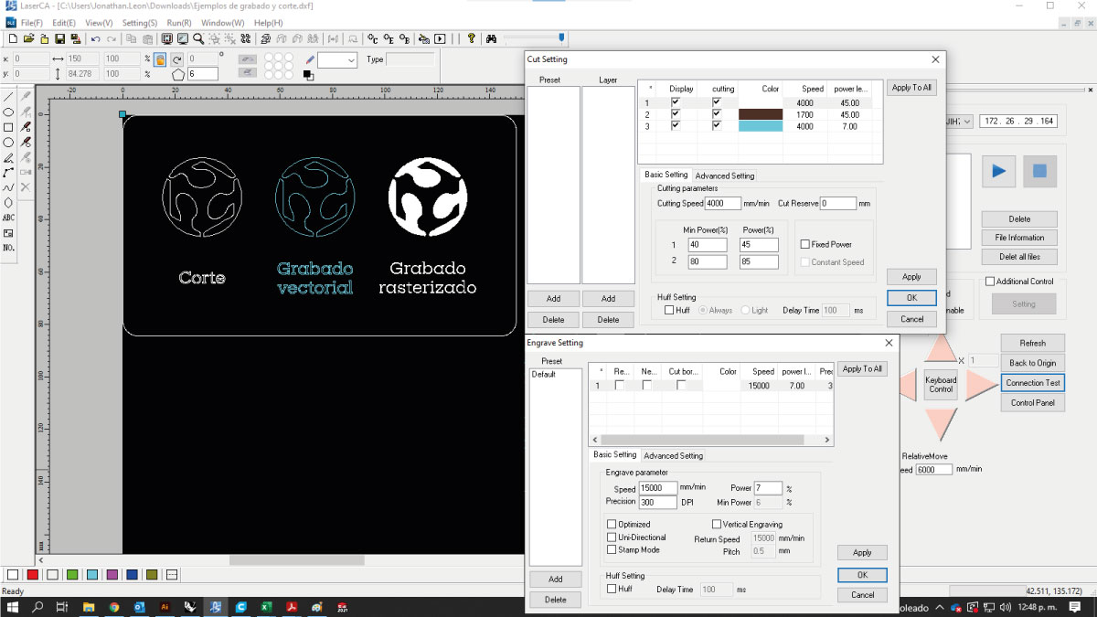
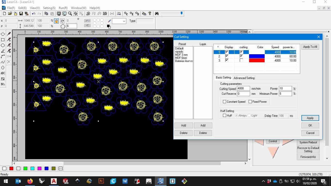
here's a screenshot of those settings
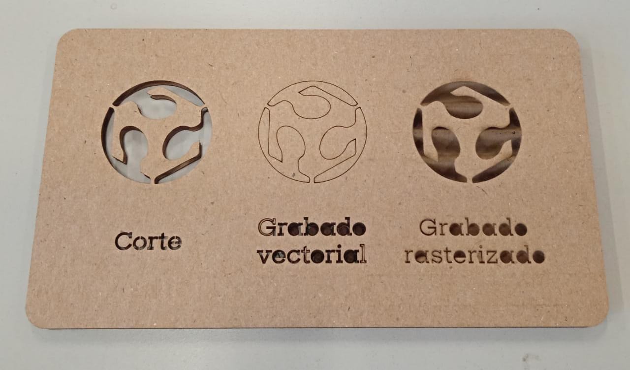
This picture is the results on the process
Also i recorded the laser working as it engraved and cut the group assignment from 2021
here you can download the characterization for our machine3.2 individual assignment
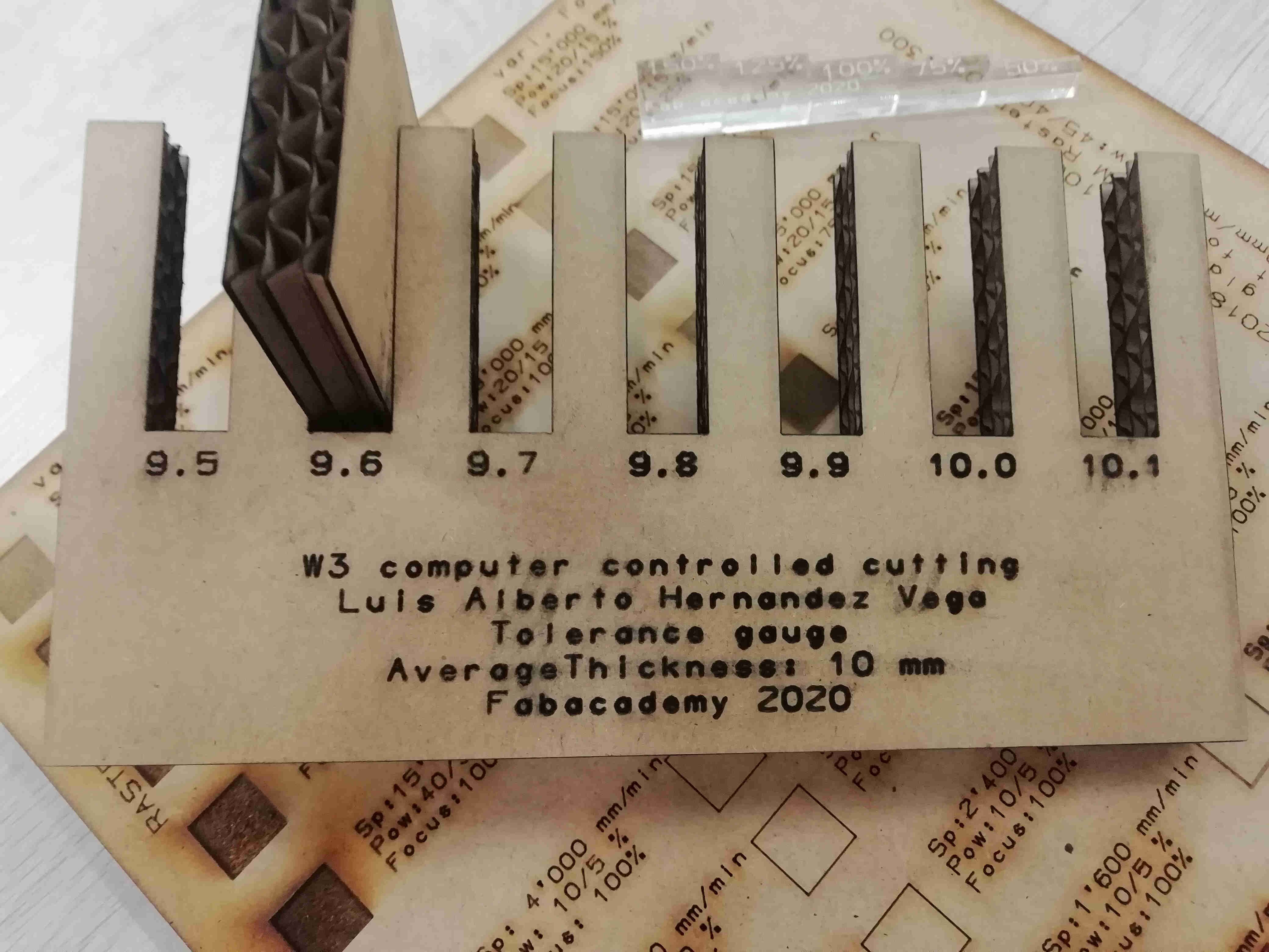
3.2.1 characterize a tolerance gauge considering the diameter of the cutter
I prepared a tolerance gauge on autocad 2018 using the pline comand and some text converted to curves in order to see wich offset worked better to the thickness of the corrugated cardboard i used to cut mi construction kit like in the figure.
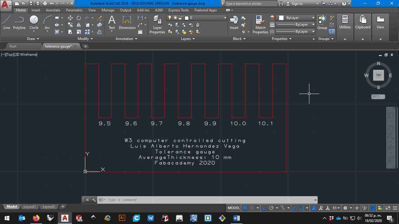
then i export it as a DXF file because that's the only vector file supported on our old machine
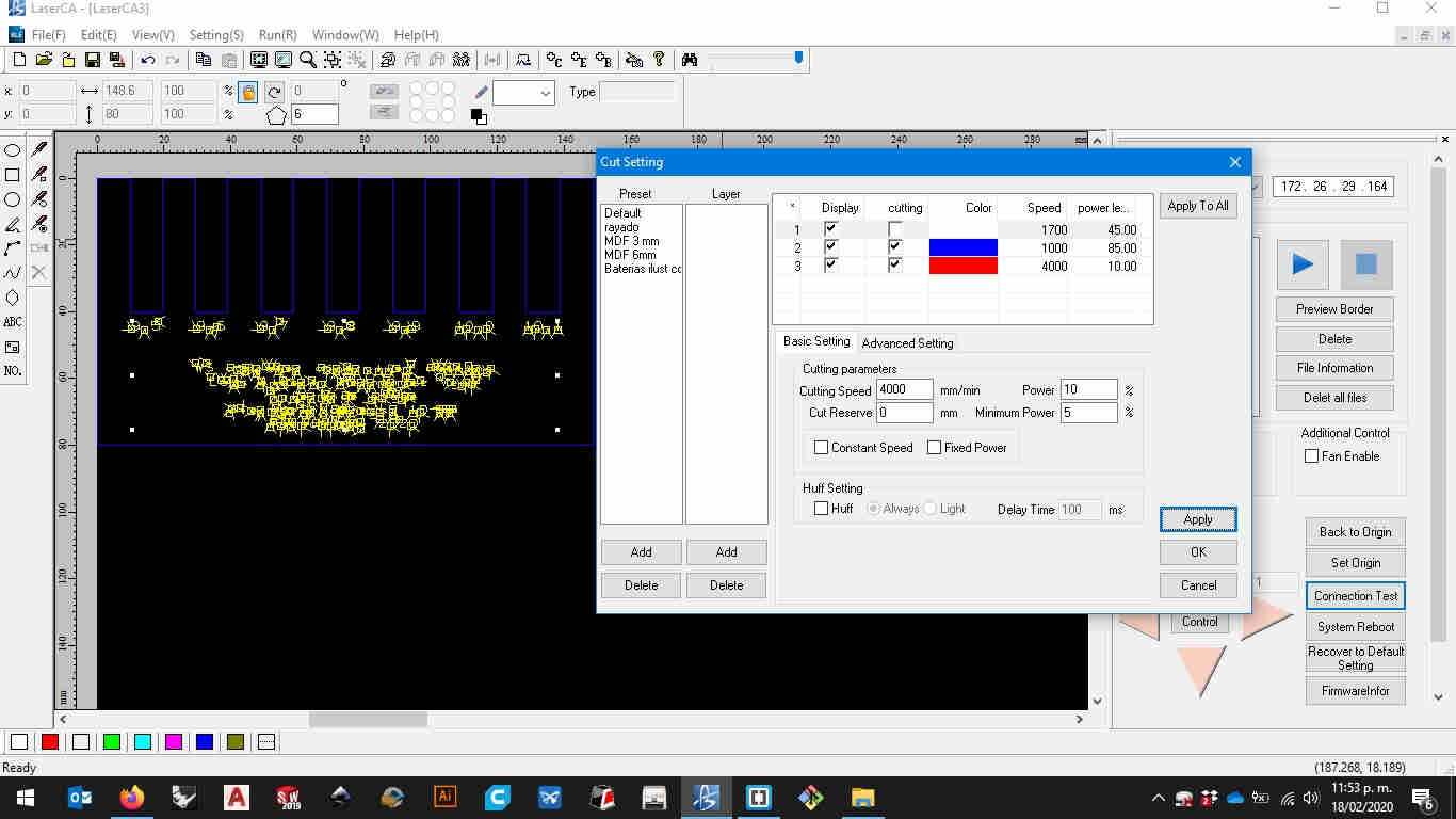
after exporting it from autocad i went and imported it on lase CA the laser cutter factory software here i entered the values for cutting and marking wich are the most viable option for my material. it is a 100W glass CO2 tube so my parameters for cutting were 1000 mm/min and a power of 85% for cutting and 4000mm/min and 10% of power for marking the 10 mm cardboard
 here you can download my tolerance gauge
3.2.2 cut someting on vinyl
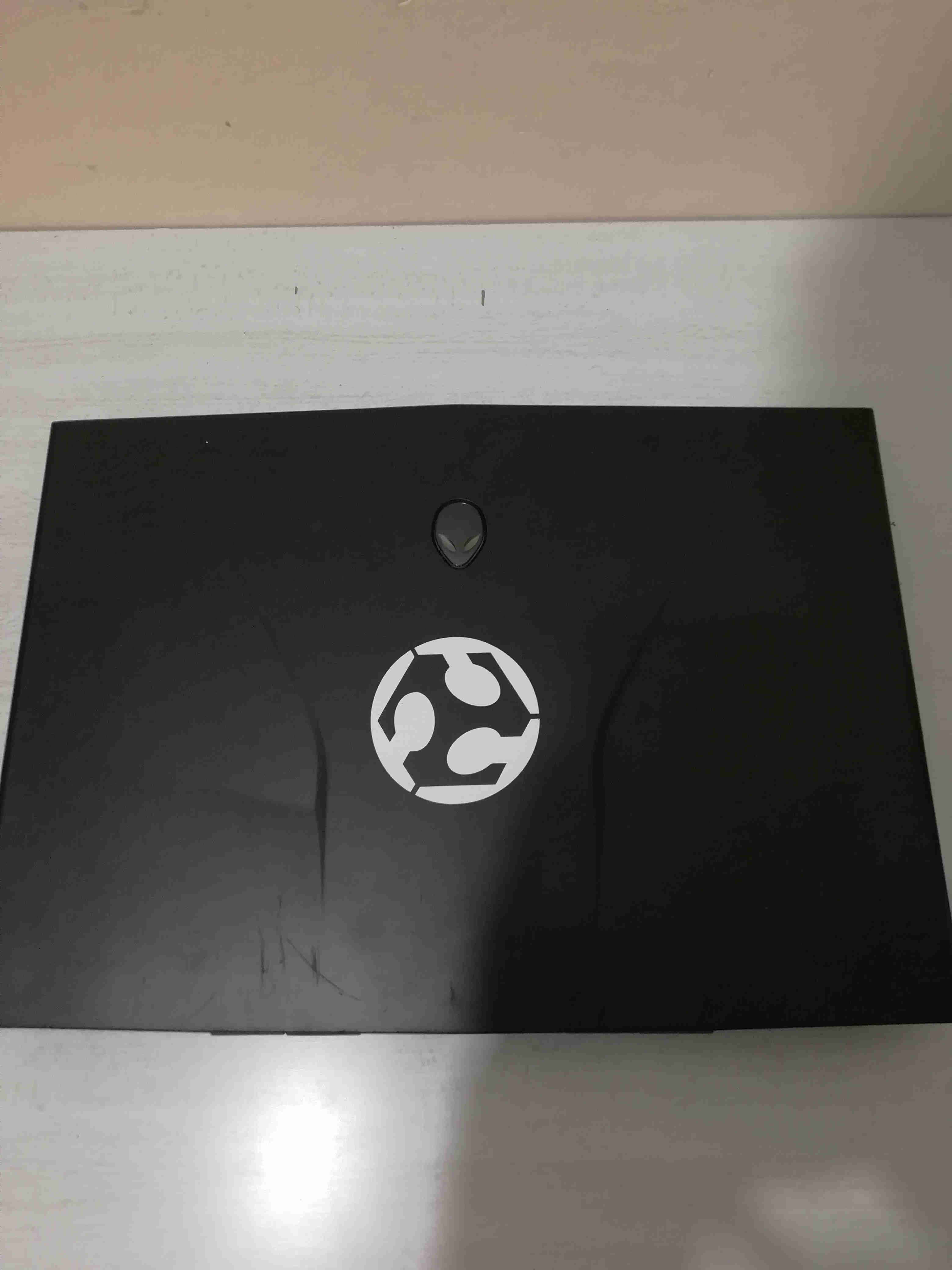
I used the vinyl cutter to make a sticker for my laptop for this i used adobe illustrator for importing the image and converting it to curves in order to cut it with the gcc expert II vinyl cutter on our fablab. Like in the figure.
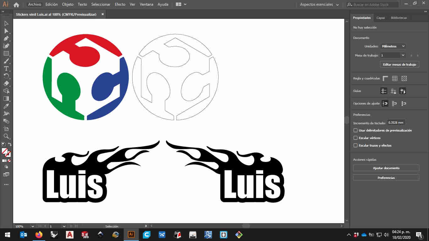
I will show you the long way to cut it but there's a shortcut that i often use with this machine
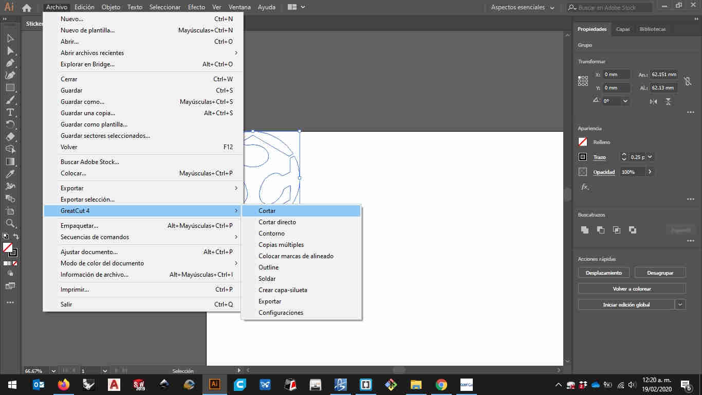
in our fablab Usually cut only adhesive vinyl that's why the settings are preadjusted to that material. so the long way to do it is to sketch the curves on illustrator and export the file to the vinyl cutter factory software wich is GCC Great Cut
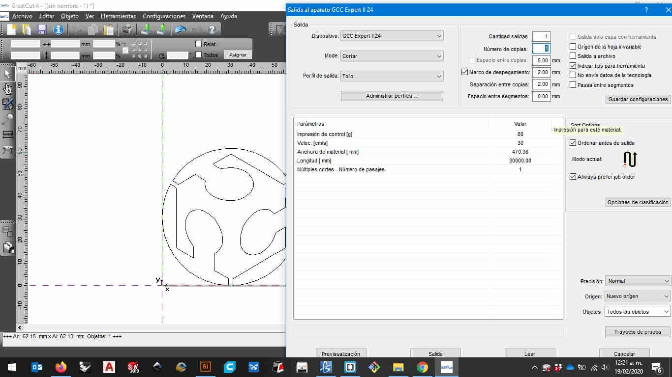
because of the simplicity of the sticker i made i just had to use 1 layer and set it to 80 gr of pressure and 30cm/s on the kinfe to get it cut the curves on the sticker but not the thick glossy papper on the back of the material
 here you can download the file for my sticker
first you'll need to make your sketch and cut it out from the software you chooose from i used adobe's illustrator because it has a handy plugin that you could use instead of using the gcc software that came with the cutter.
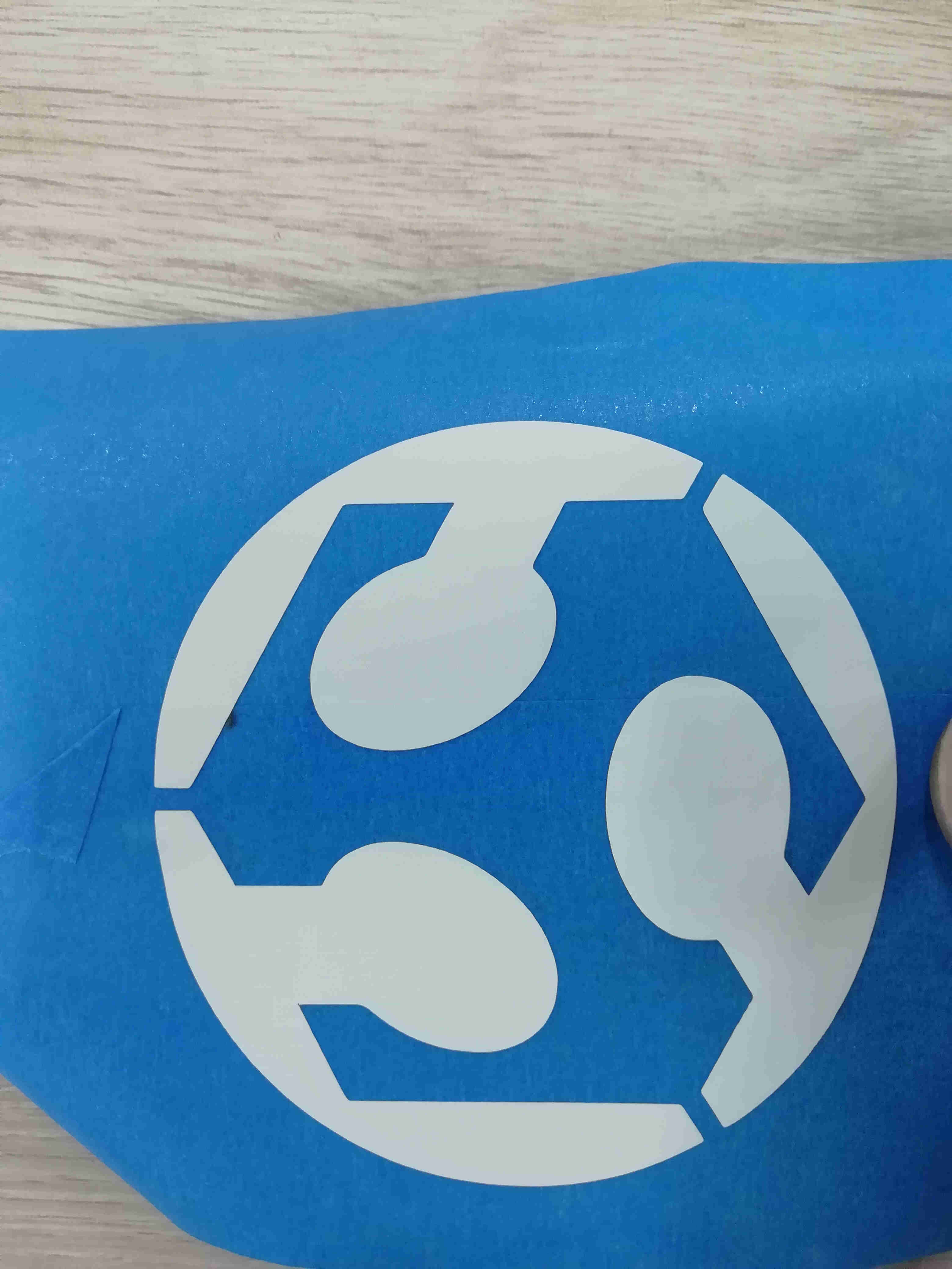
then you should get something like this
i apologise beforehand for using a white vinyl for this assignment but the black cover of my laptop should look quite nice
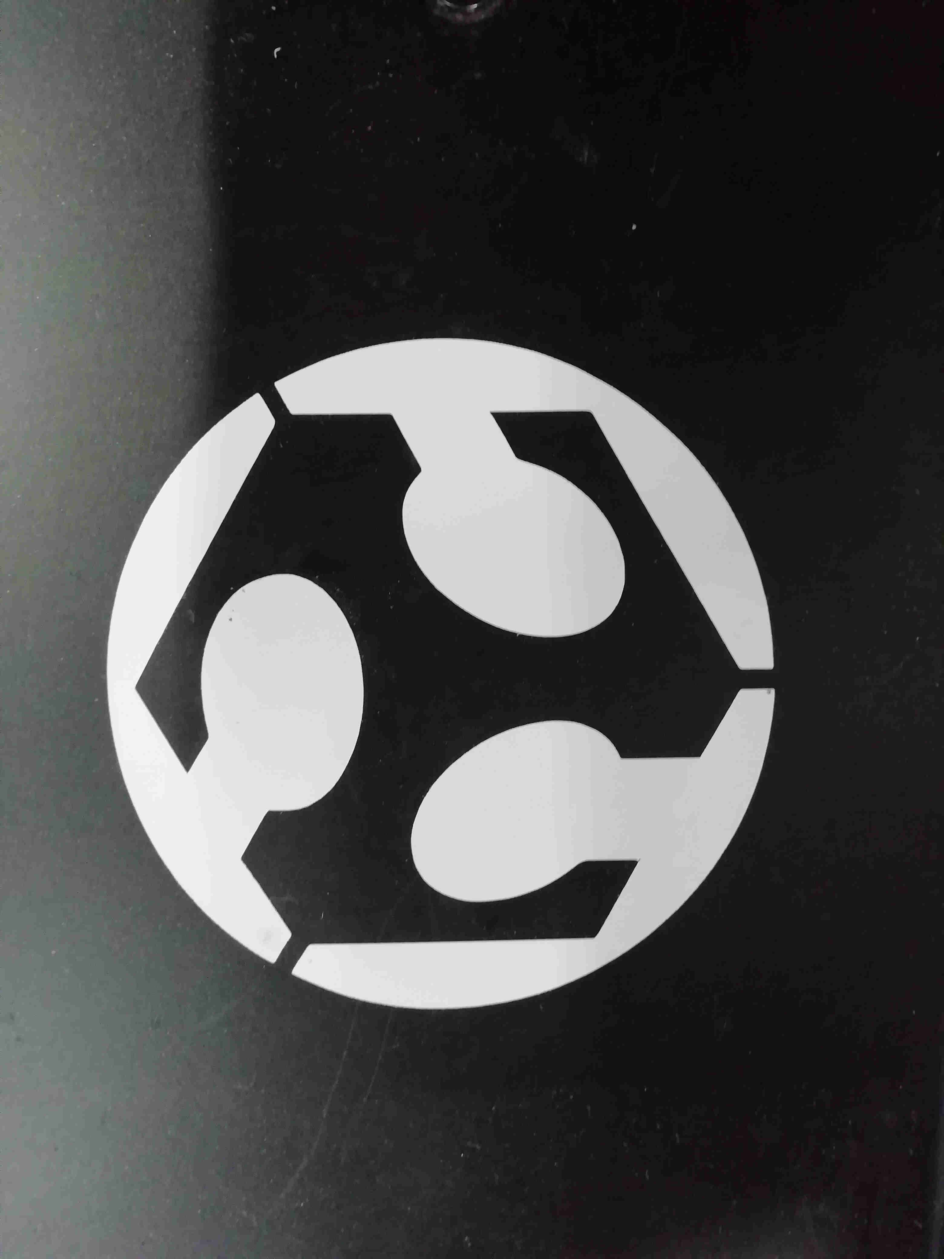
then with a pair of tweezers you'll have to remove the exxcess of material that you don't want on th sticker and when you're ready then you should get something like this
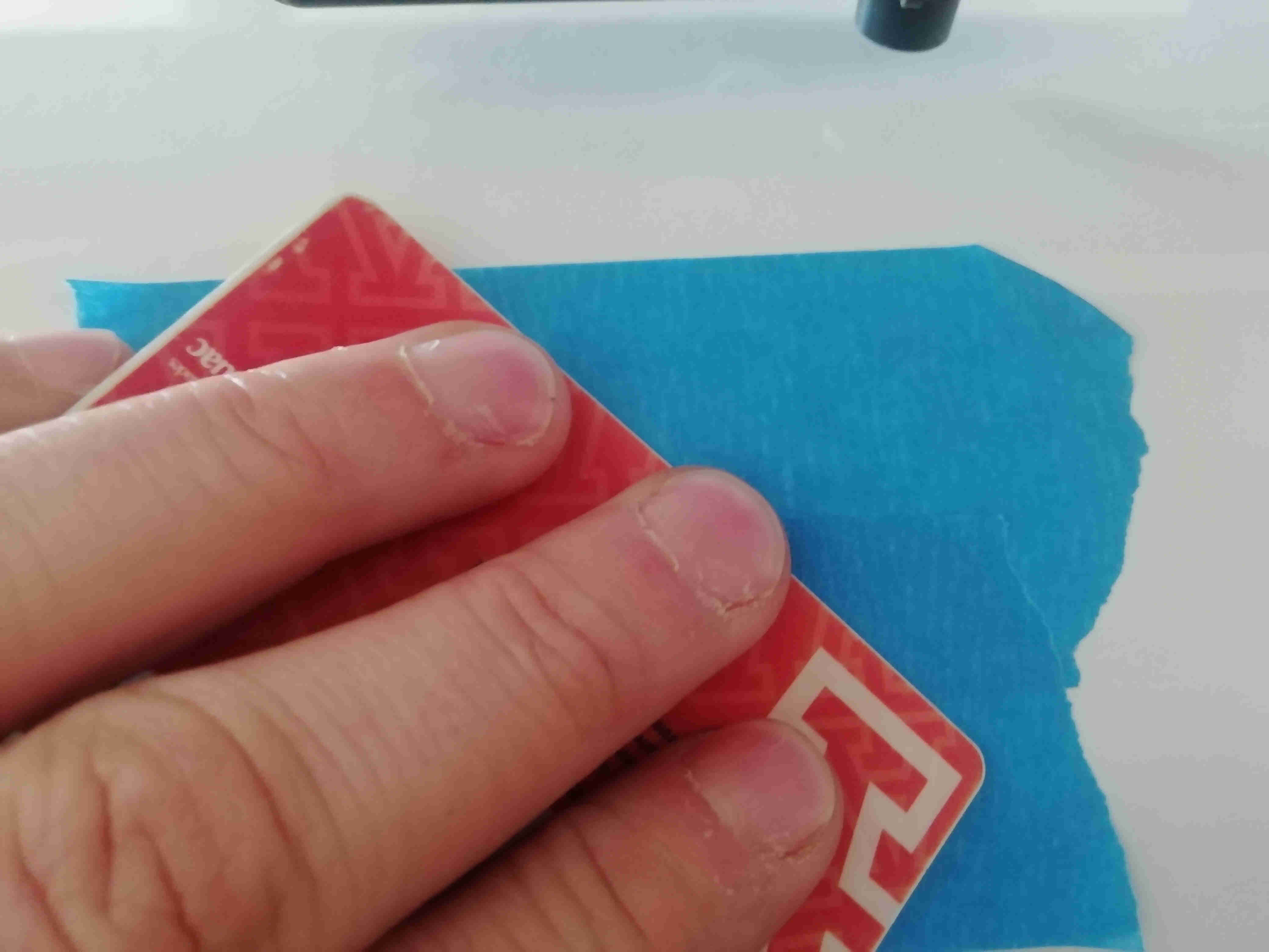
now you're ready to put some masking tape on it get yourself aid from an old ID card o credit card to make sure all the masking tape glues to the sticker
and then carefully remove the masking from vinyl material by peeling it of the backside of the vinyl
now be carefull to not touch the adhesive on the vinyl and place it on the surface you like
i failed in document this proccess in video the first time but here i leave the procces in two short timelapse videos
this a quick time lapse in the process of weeding and placing transfer.
3.2.3 draw,cut and document a construction kit
for this assignment i draw simple polygonal geometries and using the dimension on the tolerance gauge i set the dimensions on the slots i even added some chamfers as we learn on the class for getting a tight fit without using any glue.
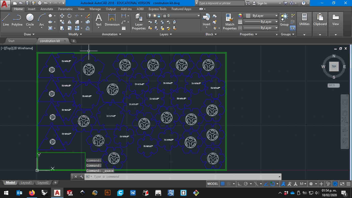
then i just simply imported in the laser cutter software "laser CA" and set the power and speed values for the material and thickness i used for my assignment
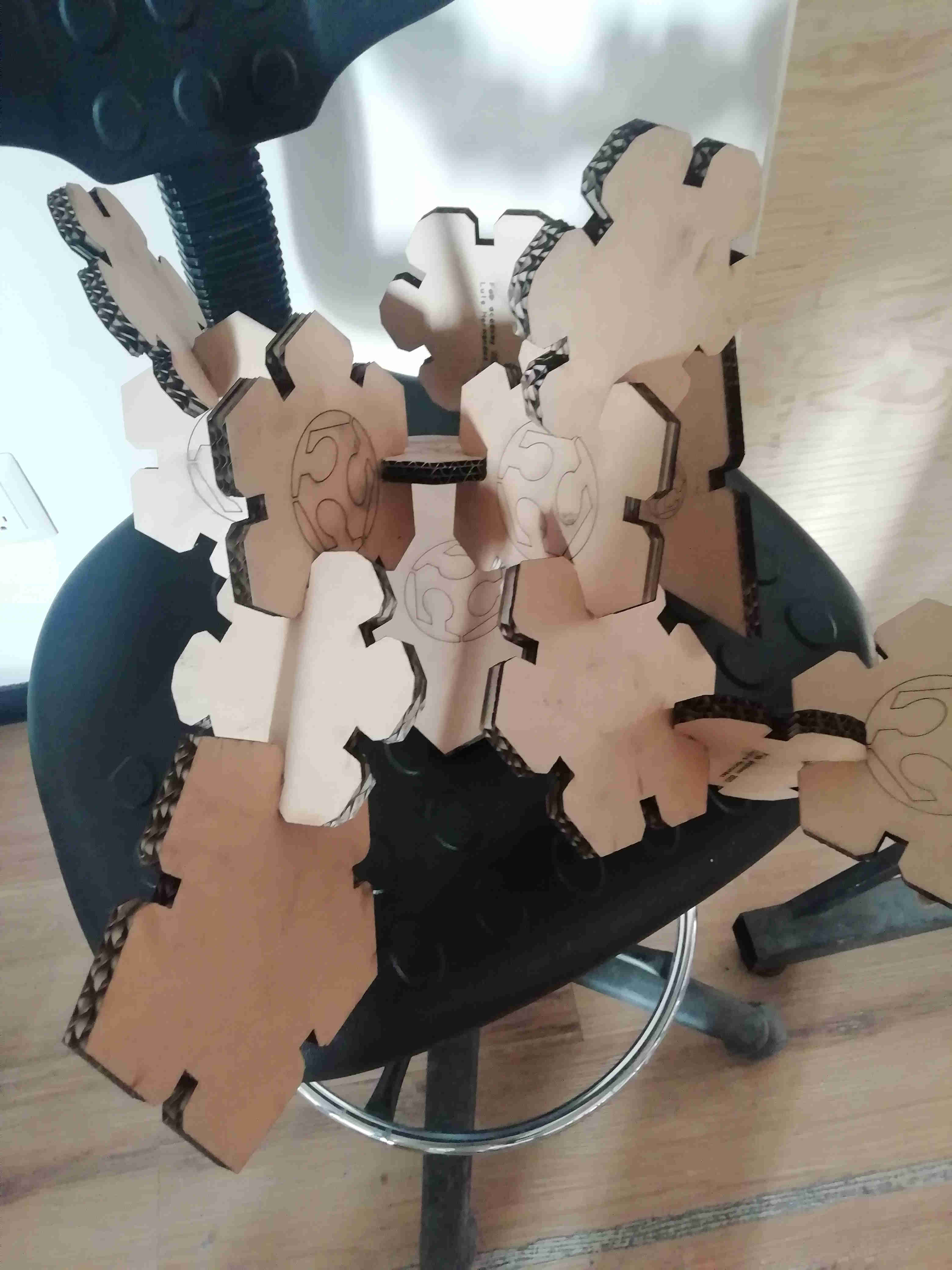
then i pull it out of the material and start playing with it making assemblies
 here you can download my file
Tutorial on parametric autocad
Here i will try to summarize a litle explanation on the video above

It's true you have a lot more of control of the procedure.
But it's really a pain in the neck when you're working with huge files.
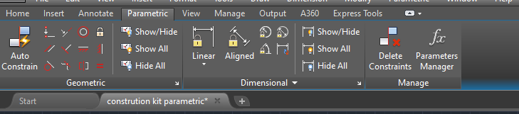
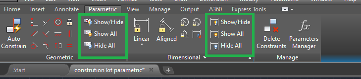
In order to make parametrical a file you'll need to use the "parametric" tab tool ribbon
from left to right and top to bottom you'll see all of the geometrical constraints.
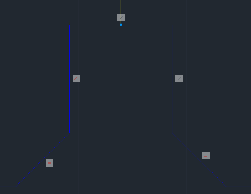
this is a screenshot on the bottom of the mentioned piece.
as you can see there are little icons on the lines that are restrained with.
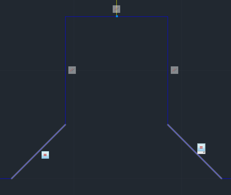
in this example the two lines that are highlighted are restrained by an equal condition.
this means that each of them have the same length.
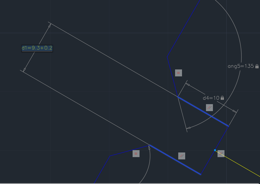
But unlike the parametric one you can not modify the dimension of the line by modifyng the number on the dimension
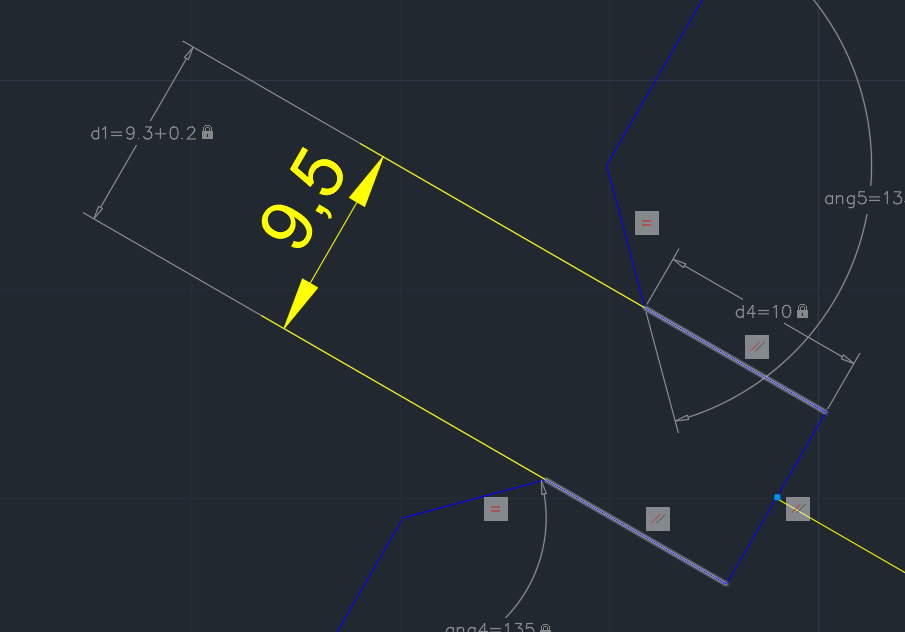
in this picture above you have the two types of the dimensions.
this function i determined by measuring with a calliper the thicknes of the material i used in my assignment (wich was a piece of corrugated carboard we had arround in the lab) and measuring the kerf of the laser machine we have in our lab this will change depending on the machine.
Our laser toolpath creator software (Laser CA) does not compensate the diameter of the laser beam.
And i wanted a tight fit on the sringy cardboard i under cutted the material by 0.1mm.
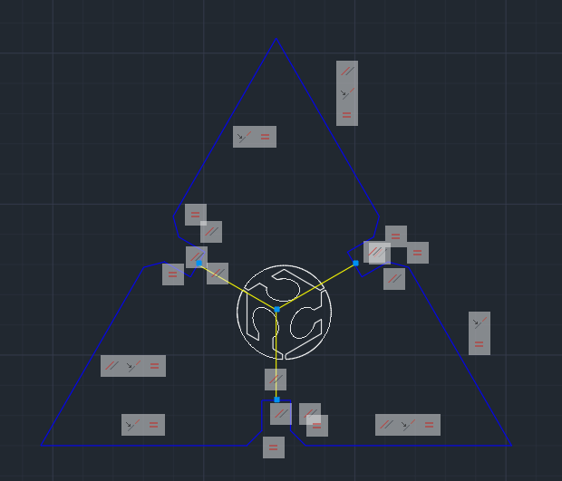
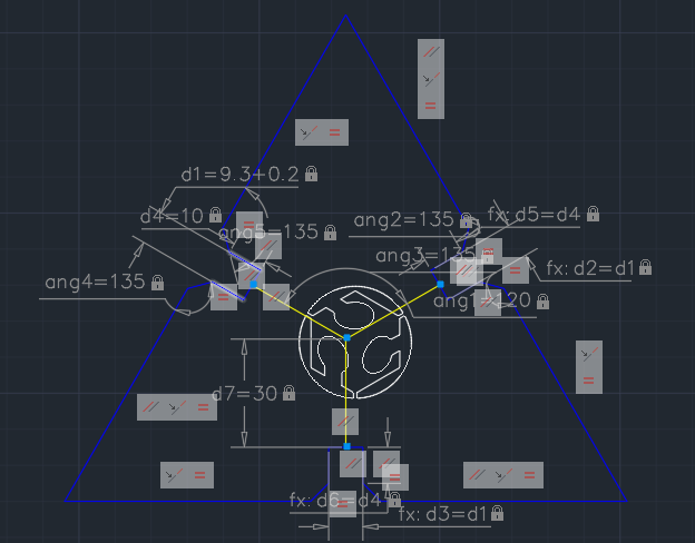
By the end you'll see all of the geometrical and dimensional constraints i used to define the piece.
Use a parametric software to make a construction kit
for this assignment i choose Autodesk's autocad because i intended to do engraving aswell as cutting operations and in solidworks it's relatibly more complex to set color for diferent layers and export it into DXF format wich is the format we use to send to laserCA our Boyelaser software. Althogh AutoCAD is parametrical in it's nature is not quite that intuitive to use geometrical constrains like solidworks do. so in this short video i will demostrate that in the file of the link you can resize the joint slot and due to de geometrical constrains keep its proportions in all the sides. in this video i'll show that i used autocad parametric constrains to build my construction kitHERE you can download the autocad file that's still parametric.
Conclusions
something of the more useful things that i learn besides using autocad and offsetting the geometry to compensate the laser cutter diameter was using some masking tape in order to extract the sticker and place it on the surface you aim to place it.
Links and references
HERE you can download the parametric construction kit (autocad file,generic parametricless dxf,toolpath file)
HERE you can download the defocuser files (autocad file,generic parametricless dxf,toolpath file)
HERE you can download the vinil sticker files (adobe illustrator, generic dxf files.)