
7.
Computer-Controlled Machining
Assignments
group
test runout, alignment, speeds, feeds, and toolpaths for your machine
individual
make (design+mill+assemble) something big
Download files
Here are the download files for this assignment, it includes the Rhino file for creating the toolpath with RhinoCAM and the resulting .nc G-CODE files. It doesn't include the original Rhino file with the design in it as it is 17.2MB.
Download all filesGroup assignment
Tue, the Queen of Group Assignments, perfectly resumed the group assignment here.
She tested the cuts with different settings by changing the spindle speed as well as the chipload, which in turns affects the feedrate. All cuts were pretty similar, the only noticeable change was the higher pitch sound when cutting at higher speeds.
The Making Of
Rather than making an armchair I decided to make a desk, because I need one for the office.
We already have a desk which is a plank of 2500 x 1250 x 20 mm plywood and the dimensions are quite nice. It allows us to have 4 big computers on the table and still have space to write or draw.
My idea was to build the same idea, some furniture with plants in it, but instead of the plants just underneath the surface in some places.

Sketches of the table
I want to make a desk that can host plants somewhere on it. I like the waffle structure because it allows to slide in plant pots in the squares it creates. In this case I want to build a desk, therefore we need some space to work on.
The plan is to replace the current desk I have at the office where three of us work on our desktop computer.
The plants will be in the middle of the table where it isn’t usually used.

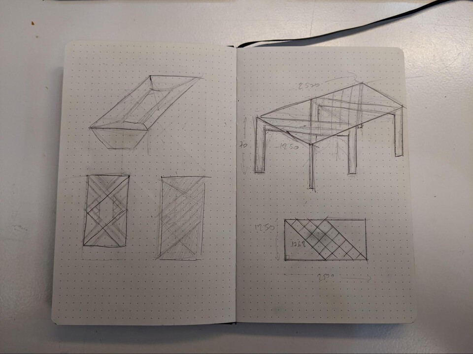
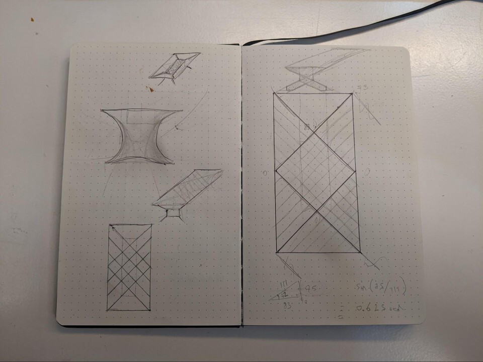
First design of the table
I’m not going to go through all of the design steps for the desk as a lot of it is simple stuff like create a rectangle or a polyline.
I’ll show tricks I think are useful or interesting and out of the standard tools when you start using Rhino.
The part where the planks of wood goes diagonally will be covered with acrylic that is 5mm. The rest of the top of the table will be 15mm plywood, therefore I need to create a 10mm difference for the surfaces to align.
Here on one of the main legs I lowered part of it by 10mm.

WireCut
I used WireCut a fair amount to cut shapes in multiple objects, making sure it’s all aligned. It was most useful when doing the T-bones joints, or in the case below, cutting a specific size out of the planks.
I selected the edges created on the legs in the previous steps and duplicated it, creating a separate curve.

Then I selected the WireCut command with the curve selected, it the asks for the objects you want to cut, selected the planks and pressed Enter. It cuts off parts of the planks and fills the void with surfaces.
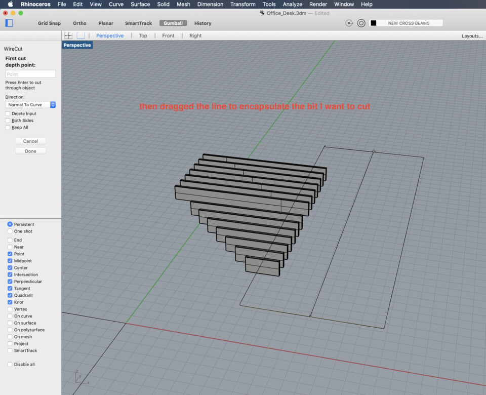


Making the planks thinner
In the end I decided to make the planks of wood 50mm in height rather than 100mm, because otherwise it'd be too close to your leg. I also added some “chamfer” to make it look nicer and also help with the leg space.

Some more WireCut
I added the little T-bone holes to make sure it fits together after. I made sure to have a 0.1mm offset so that it’s not too tight when assembling it.

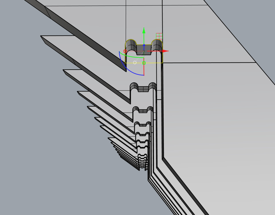
Finally, using the same technique, I added all the slits needed for the insertings.

Tracing the outlines with Make2D
Now I have everything, I use Make2D to project the outlines to the CPlane which I can then Join and use to laser cut.


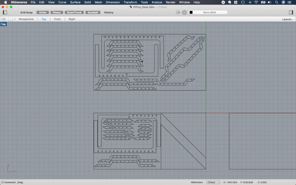
After rotating all the pieces so it was parallel to the CPlane I used the Make2D function to create all the outlines. Below in yellow is a 2500x1250mm material. I have to nest the outlines to create the best use of space. I have to make sure to keep at least a 6mm gap between all the pieces to create the outline (that’s the width of the endmill).

After hand nesting all of it and including the two half squares I see I need 4 sheets of plywood… which is quite a lot. I could do with 3 and not have the 2 triangles and cut it from some nicer wood, but it’s still 3 plywood sheets.

What if I scale everything down so the table is smaller? If I scale everything down to 80% the current size the plywood would need to be 16mm thick, and would make the desk 2000x1000mm… it would fit on only two pieces of plywood, even with the triangles…
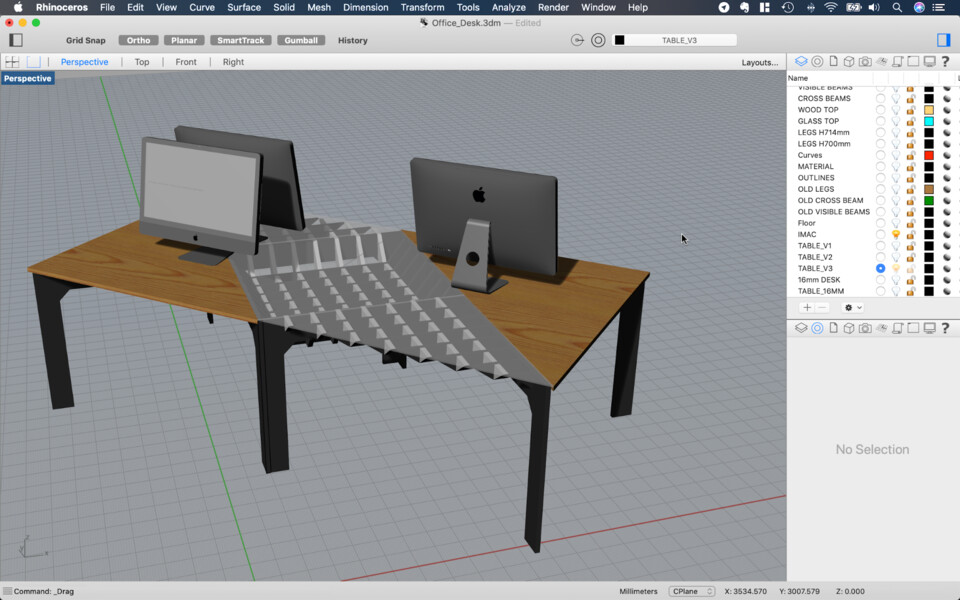
… but the desk would be too small I think. Look at the size of the computers compared to the full size.

Anywho, I made a cardboard laser cut version of the table to have a physical version and see how it’s going.
First review with Edu
After talking to Edu and making a laser cut cardboard version of the desk we came up with a few notes:
- Use 15mm plywood everywhere (not 20mm), because that’s what we have
- Use 5mm acrylic
- Use whatever I want on top for the triangles of wood
- Chamber the legs so that if you drag the table around it doesn’t get stuck
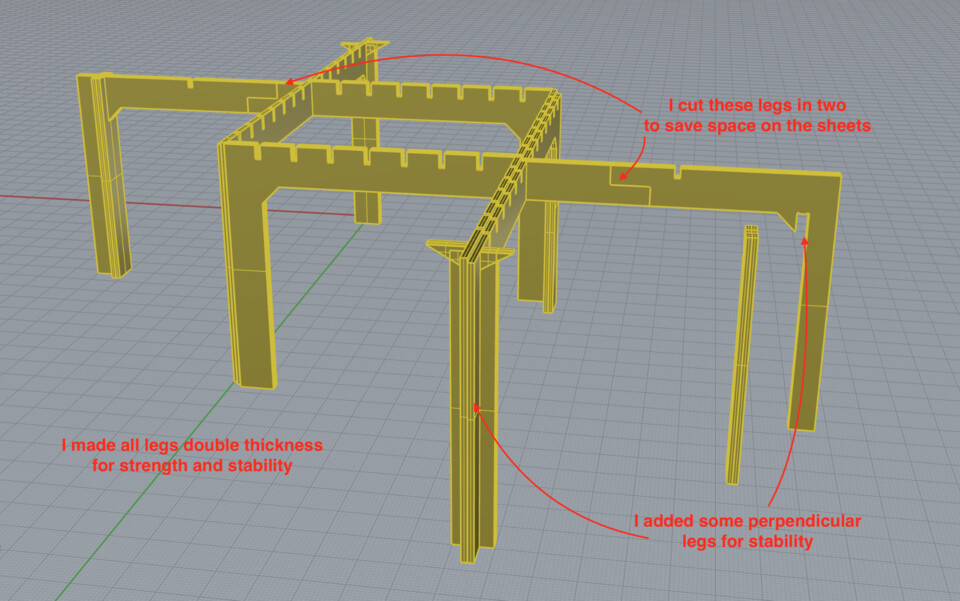
- Maybe double up the leg
- Slide the slices to make squares
- Replace the last little slice with one that goes all the way to the ground to stabilise the legs
- Where the slices lowers to make space for the plants, make it thicker as at the moment it’s too thin and fragile
- Where the legs of the table crosses, flip the t-bones for better structural integrity
- Cut a pocket / cross in the triangle so that it aligns with the leg below -> stops the leg from moving too much around
Second design of the table
Here’s the new version of the desk, with double thickness legs, 15mm plywood.
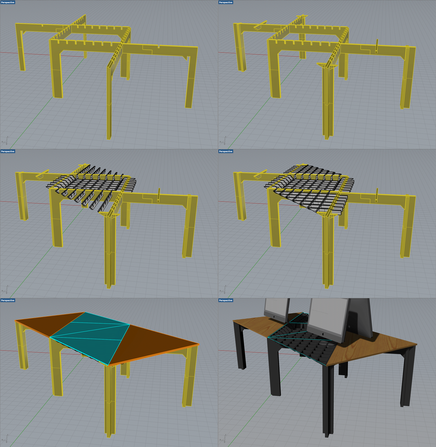
Few interesting details, like double thickness legs, cutting them in half for saving space,
I made sure to offset the curves by 0.1mm as the wood isn’t usually exactly 15mm. I measured a few plywood sheets and they were around 15.2mm. Hopefully the machine will cut an extra 0.1mm and make it easy to slide with each other…

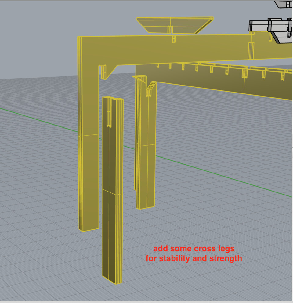

Added chamfer so that the pieces slide in with each other more easily.

And of course reMade2D all the outlines.
Nesting the curves with Deepnest
I had first nested the pieces by hand on Rhino, but for sure wasn’t the most efficient way of doing it.
In the end I used Deepnest for the best layout of the curves for milling. It’s easy to use once you figure it out (or just read the website, like I didn’t).
I exported all the curves from Rhino to a DXF files.
Then open Deepnest and clicked import and then selected the DXF file... the software supposedly accepts DXF files but it didn’t work, so from Rhino I exported it as an Illustrator file and then in Illustrator exported to SVG.
Note //
I think the DXF file didn’t work because I had exported the entire Rhino file rather than just the outline. Later I selected the outline and did Export selected and exported to DXF. I managed to import them into Deepnest but it didn’t seem to want to nest them (they were all red and didn’t appear on the left)
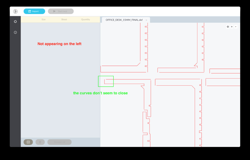
Click Import and choose an SVG file. It appears straight away.

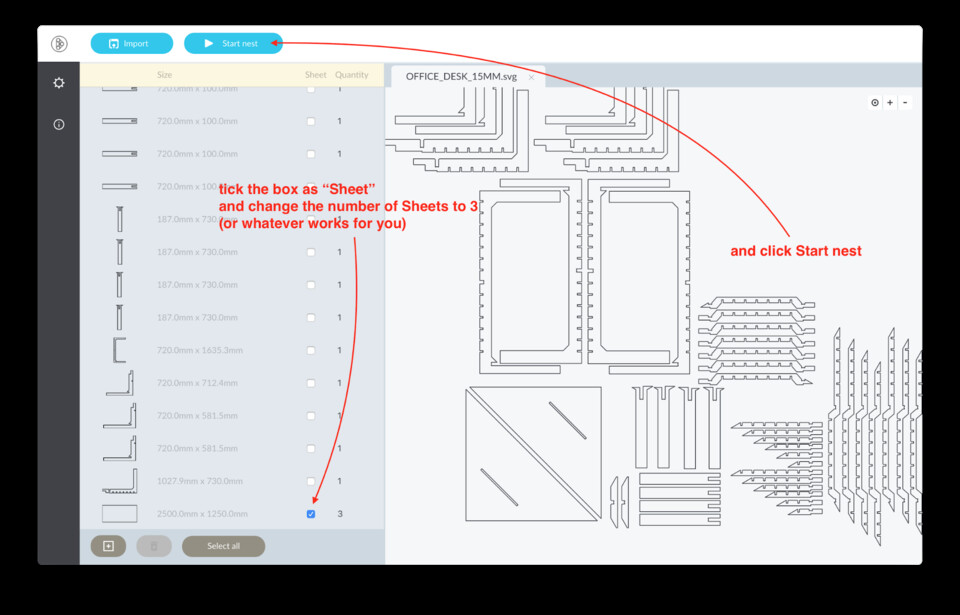
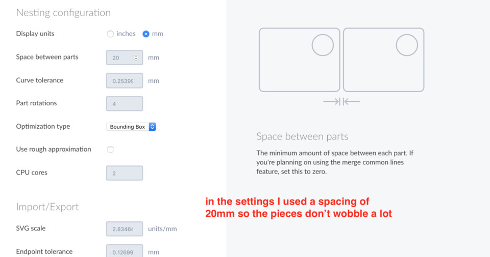

I tried a different design and ticked “Use rough approximation” in the Settings, but what it did is that it created an invisible rectangle around the pieces which means pieces couldn’t be nested in.
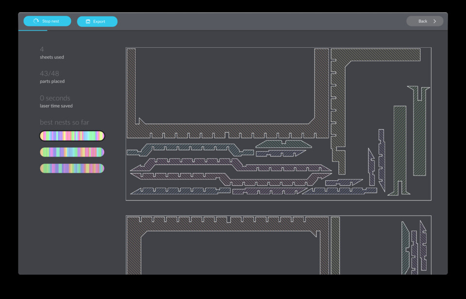
I unticked it and tada, it started nested again (it went from 5 sheets used to 3).
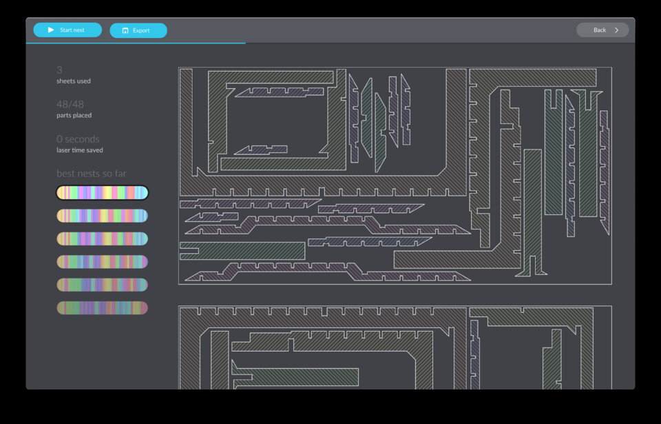
Stop the nest and then export it. You can export in DXF or SVG, I did both.
Creating the machining toolpath
Now I have my outlines nested nicely, 20mm away from each other, time to create the toolpaths. I decided to use RhinoCAM as that’s what we have at the lab and I had used it once before.
I imported the DXF that Deepnest gave me, but the scale was completely off. No worries, select all, use the Scale function, select one of the gaps of the T-bone and type in 15.2 (that’s how I designed them).
Then I decided to cut only 3 pieces first two see how they fit with each other. I chose three pieces because all the dog bones are the same width, except one that is double the width. Cutting 3 allows you to try both joints.
Creating the stock
In Rhino I selected the 3 pieces I wanted to test, then headed to RhinoCAM and created a new machining job. We have to first select the Stock, in my case it’s a 2500x1250x15mm plywood. Make sure to select where the Z0 will be, in my case on the top.
Creating the tool and calculating the speeds
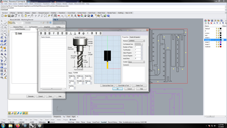
Create a new tool, in my case it’s a 6mm single flute downcut.
Note //
A downcut flute pushes the wood chips down, which makes for a cleaner top surface. You also have to be careful for the endmill not to cut straight down as the chips would have nowhere to go, they’d be pressured and create a lot of heat. Always move sidewards when using a downcut flute, except if you are only doing little dots for screws in 2mm of wood, like in this case.
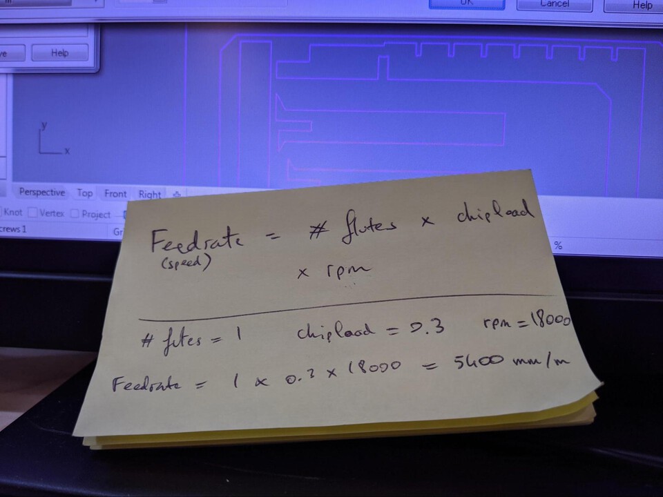
You can calculate the feed rate (speed) by using this formula F = # of flutes x chipload x RPM. Chipload can be found here. For a 6mm diameter tool with plywood material the chip load is between 0.28 and 0.33, let’s use 0.30.
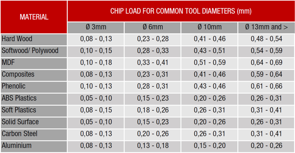
Using that formula we have Feedrate = 1 x 0.3 x 18000 = 5400

Placing the screws with points
Before anything though, I placed points where the screws will be, as there will be a lot of long pieces and they might wobble around. In total I placed 33 screws. That will ensure I don’t screw the plywood to the sacrificial board too close to where the endmill will go.

Creating the profiling Machining Operation
Add documentation about profiling, etc.
I decided to do the profiling in two steps. As I said previously, a downcut flute pushes the wood chips down, and therefore gives a cleaner top surface as it doesn’t rip the layers of the plywood up… but when you arrive at the bottom of the wood, it will damage the surface. I’ve decided to do half of the profiling with a downcut, and the other half with an upcut. That means that it asks for more work, as I have to change the endmill for every operation, but in the end it gives a better finish.
Setting up the CNC
Measuring some planks, this one is 15.2mm-ish.

Setting up the CNC with the help of Josep (always following the mascarilla rule, what an example citizen).
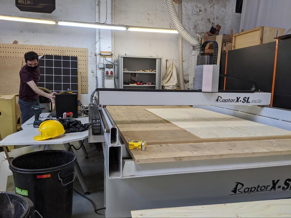
Setting the X & Y by eye. Not sure if there’s another way to do it.

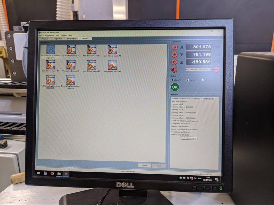
Setting the Z with a cool nifty tool, it lowers until it clicks a button. It knows exactly how tall the device is and therefore knows which height it is at. The previous CNC machine they had used some metal plate where when the endmill touched it it would close a circuit and tell the machine it arrived.

On the right the machine coordinates of my X & Y’s 0s. I take a picture in case something goes wrong I can then re-enter the coordinates manually and set up the X & Y zeroes again.
Cutting the test pieces
After cutting the 3 pieces I put them together and they would not fit, at all. I measured the actual size of the t-bones and they were “way” smaller than I had designed them. I thought they’d be a bit bigger, as the endmill might wobble a tiny bit.


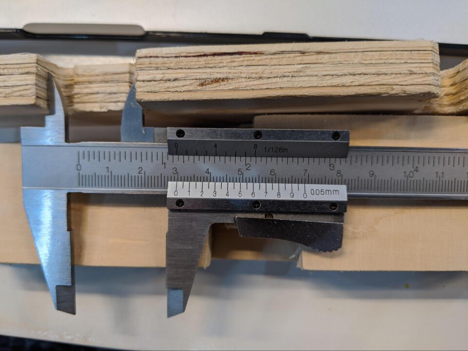
So I added an offset of 0.3mm, which would make the slots 0.6mm wider in total.
Problem with offsetting some curves
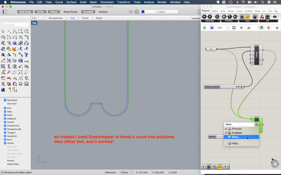
For most curves the offset function worked fine, but a few seemed to be broken or giving errors.


Edu showed with a simple Grasshopper script that takes all the lines from the geometry and joins it with the To Polyline module. You then plug it into an Offset module and set the offset. It was also useful to quickly offset all the curves in the project rather than doing it one by one.
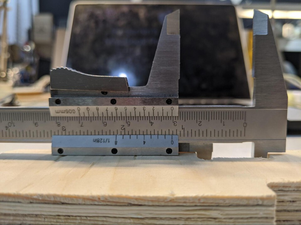
And here you can see it’s now 30.5mm, how it was originally intended (I set it to 31mm in Rhino).

For my test run I noticed the last layer wasn’t cut properly. It could be either because the sheet is a bit larger than the first one (it was 15.4 instead of 15.2), or the sheet isn’t properly flat on the bed.
Note //
After checking it was something different: I had done the Z calibration for marking the screws, but because the sheet wasn’t perfectly flat on the bed it was 1mm higher than it was after I screwed it in. When I launched the cut the sheet was flat on the bed and therefore lower than before. Luckily it was just my test cut for that sheet, so I simply reset the Z and away I went.
Cutting all the pieces
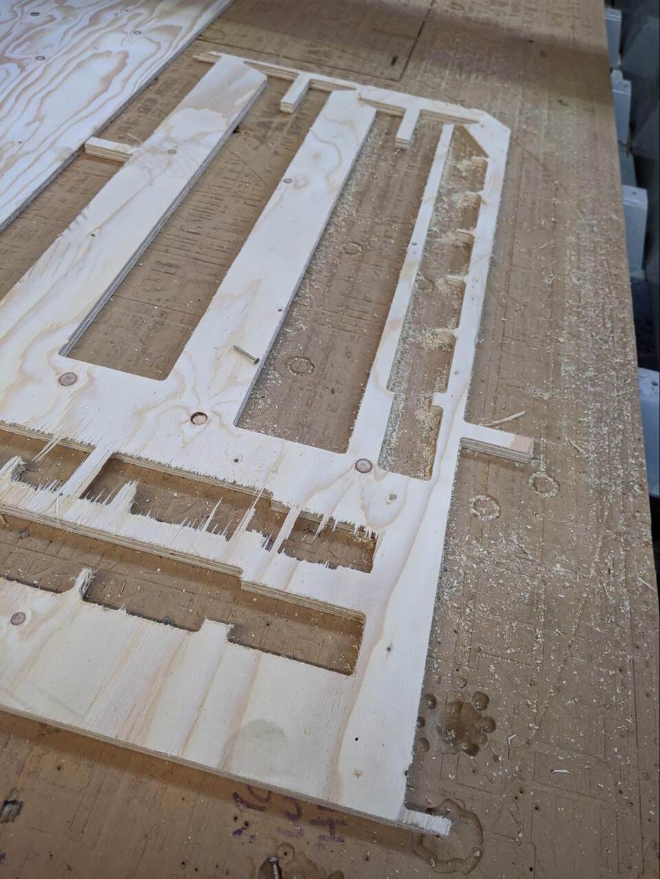
Ok, I’ve done the tests, I can now cut all my pieces. All the operations are the same as before, adding screws, profiling, and that’s it.
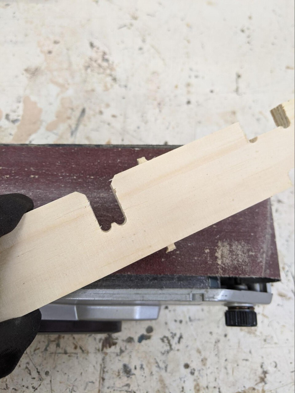
My table is finally all cut! I sanded the bridges that kept the pieces attached to the rest of the sheet and not rattle, and the edges where some shards were sticking out.
Left them out overnight, and of course it was the only day of the month in Barcelona where a massive storm came and leaked in one place in the lab, my freshly cut wood.

All wood is cut, it’s time to assemble now.

I had a piece of wood missing somehow, so I took one of my leftover sheets, found someplace where the piece would fit and cut it.

Cutting the two triangles for the table top
Finally cut the two triangles for the top.
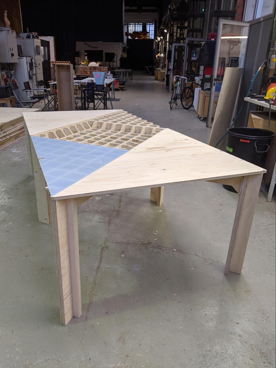
It entailed pocketing the bottom for 10mm, leaving 5mm on top.
Pocketing machining operation
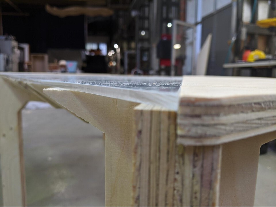
This pocket fits with the piece of wood that keeps the two legs together (you can see in the picture below), and allows for the triangle not to move but also to improve stability of the legs.

Antoine working on his invisible computer (a Linux)
 This works as a hero shot, right?
Download files
Here are the download files for this assignment, it includes the DXFs from Slicer, PNGs for Mods, and the .nc G-Code file. It doesn't include the Blender file as it is 19MB.
Download all files