
2.
Computer-Aided Design
Assignments
group project:
model (raster, vector, 2D, 3D, render, animate, simulate, ...) a possible final project
compress your images and videos, and post it on your class page
Download the files
Table of contents
FreeCAD
- Sketching on paper
- Modeling on FreeCAD
- Padding the sketch
- Creating a sketch on the face
- Centering the sketch to the middle of the face
- Copying the sketch on the other face
- Playing with the variables in the Spreadsheet
- Creating the bar
- Exporting both object to STL to animate and render in Blender
Blender
Have you?
FreeCAD
Sketching on paper
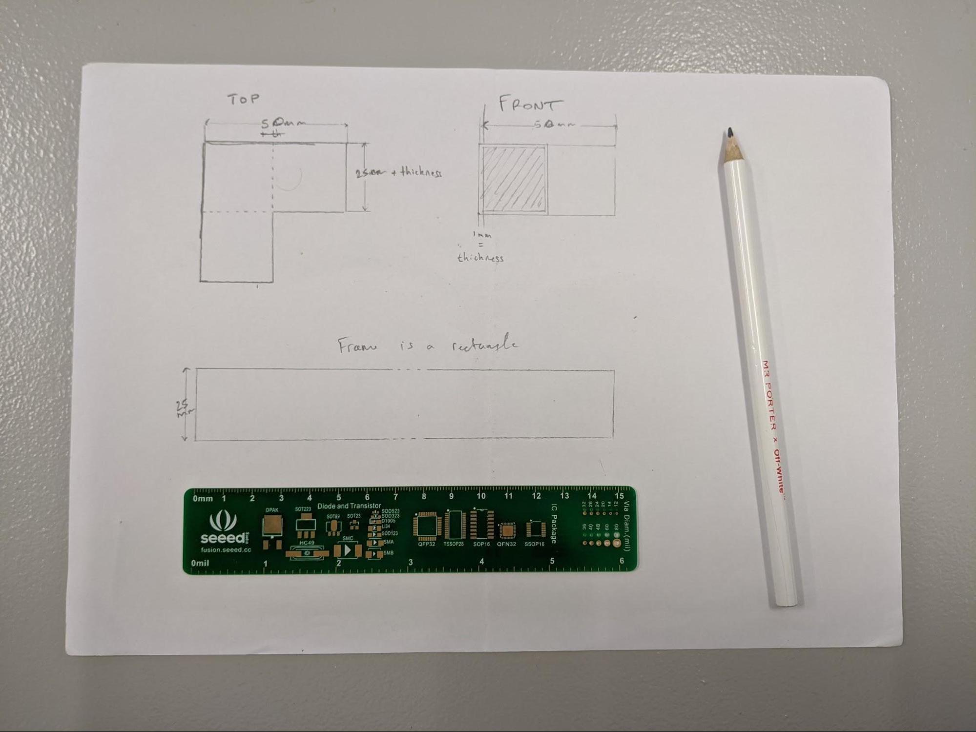
I started by sketching a simple design first, on paper. It helps me understand what needs to be taken into account before starting. For example there needs to be a thickness to the corner piece where the bar will be slotted in. It also needs to take into account the size of the bar, and how deep to go.
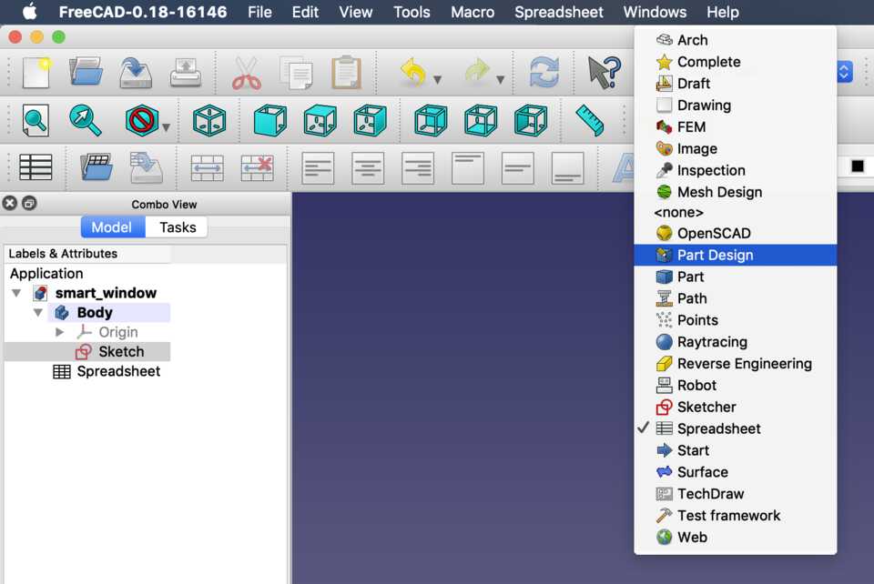
Modeling on FreeCAD
In my CAD software of choice (I’m going for FreeCAD so that I can use it anytime anywhere in the future) I created a sketch and roughly added the outline.
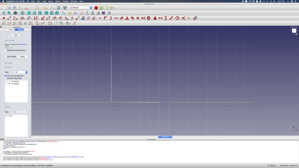
Above, a simple L shape with the line automatically constrained to vertical and horizontal.
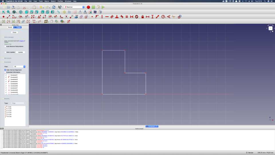
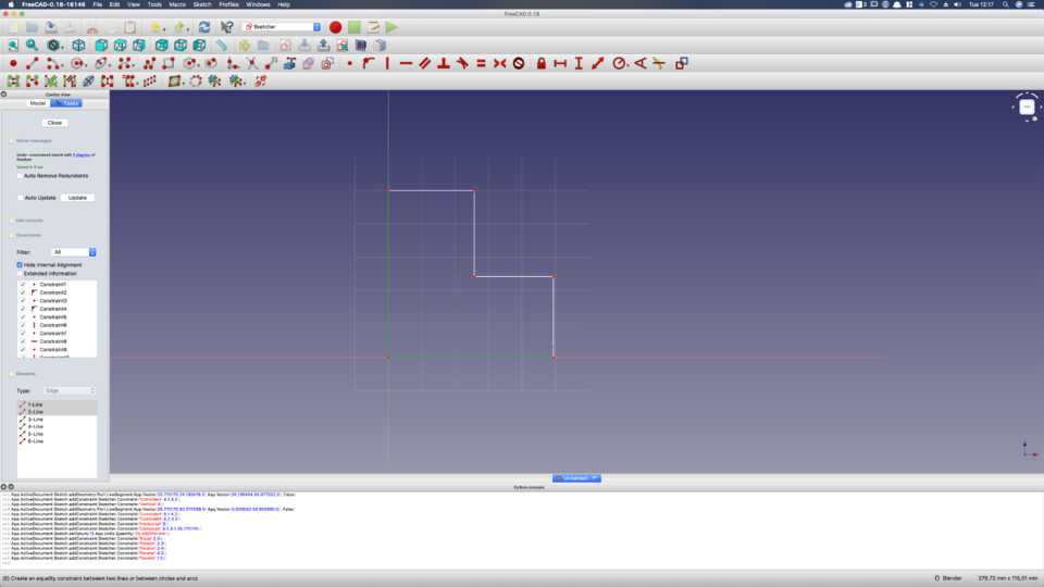
Adding the “steps”. Right now I don’t care about the length of the lines, I just want to make sure they’re constrained horizontally and vertically.
Here I tell these two big lines to be constrained to the same length. (Later realise it is not necessary, on the contrary it’s redundant.)
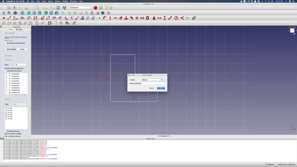
Then I constrain these lines to a certain length.
The two lines are the same length. Now let’s constrain the length of these 4 lines.
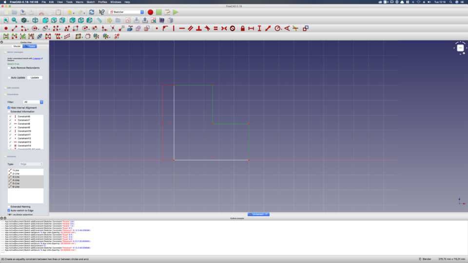
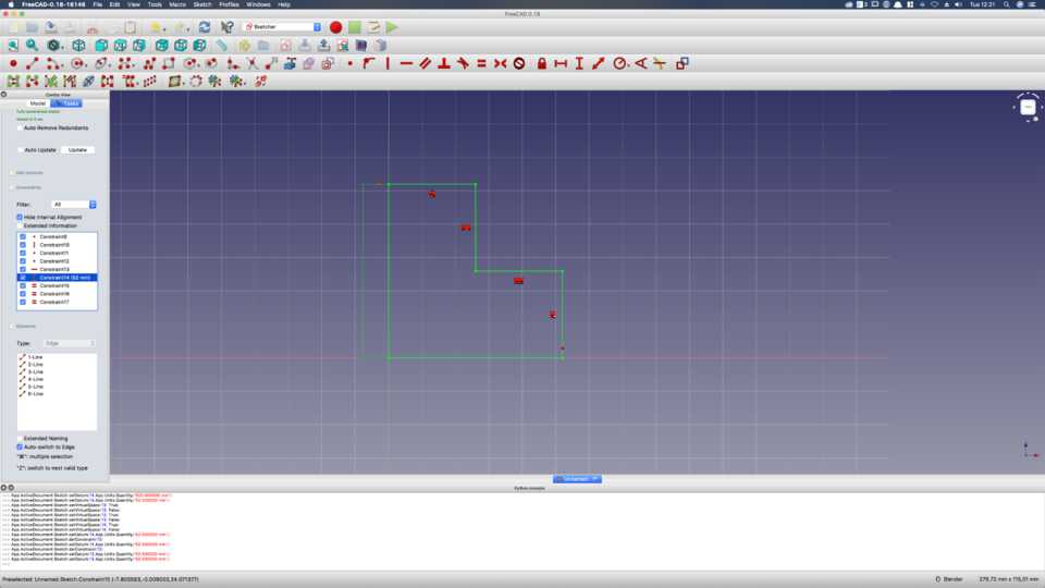
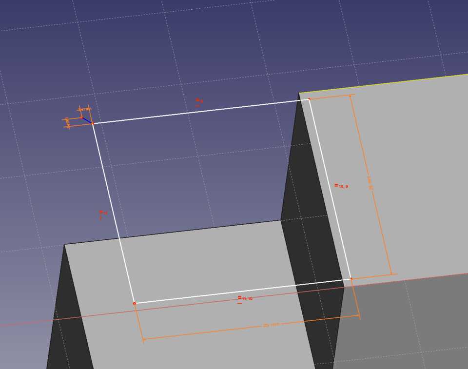
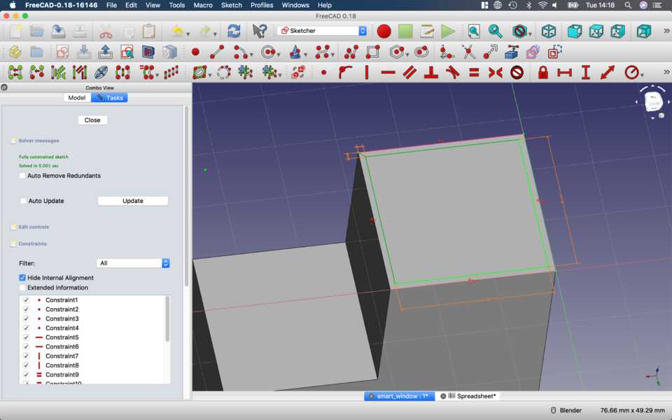
The sketch is green, showing that enough constraints have been added. It won’t move around. But wait… I actually want the length of the lines to be 52mm, so later I can Pocket into the face to create a slot, with a fixed thickness.
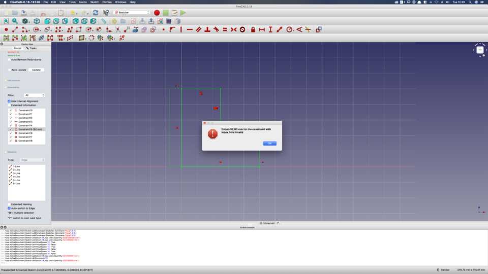
Problem is, FreeCAD doesn’t let me do it. When I try to change the length of the left edge, it says constraint of index 14 is invalid, which is the one that says the two edges are the same size… so rather than extending the other edge, it just says you can’t.
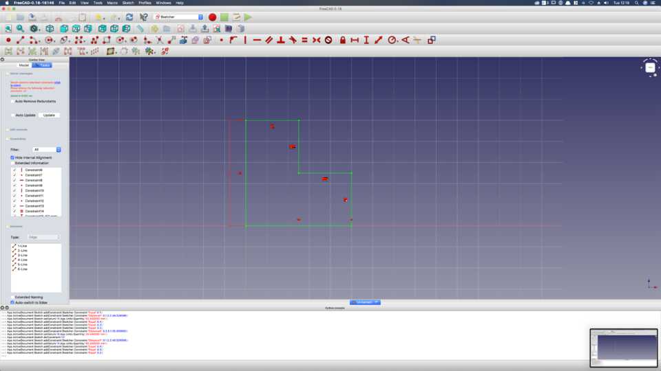
I thought “maybe it’s because one constraint was added before the other, so it tries to satisfy them in order… what if I delete constraint 14, and add THEN the length constraint”... so I deleted the constraint.
But wait again… it’s still green… it has all the constraints it needs, and that’s because the 4 lines on the right need to be equal, and therefore automatically determines the length of the line at the bottom… so I only need to give the length of the left edge… and it works!
Padding the sketch
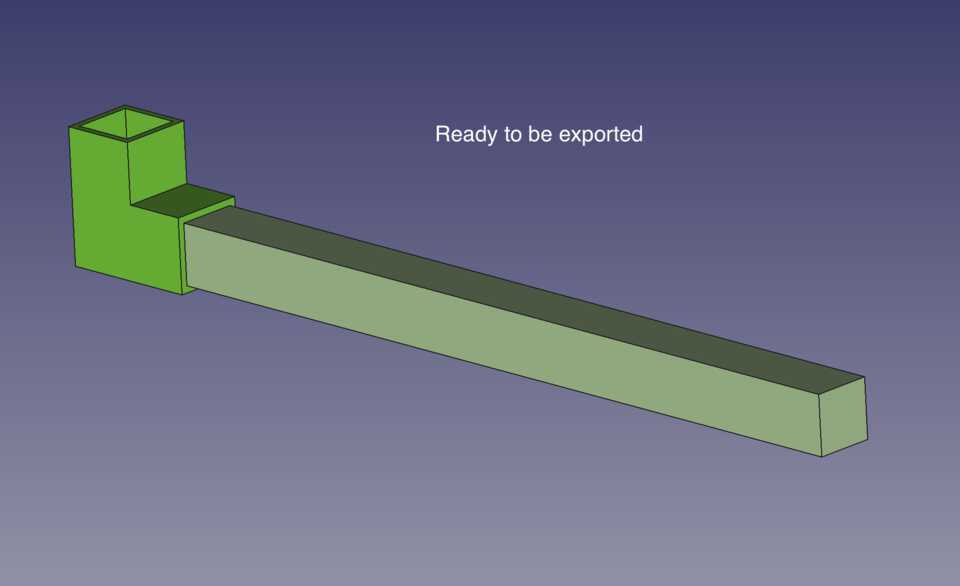
Now my Sketch is ready to be Padded.
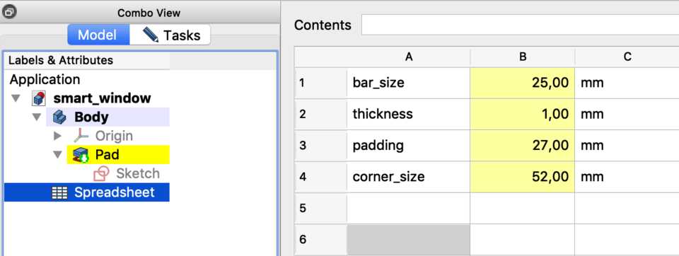
First let’s create a Spreadsheet so that the Padding is constrained to the width of the bar (bar_size from now on).
I’m going to create a few variables:
- One that is the width and height of the bar, called bar_size.
- Then I’ll create a variable that’s the thickness of the shell.
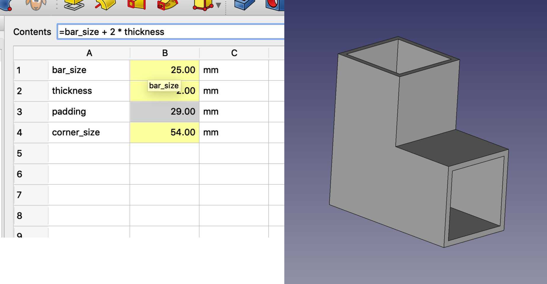
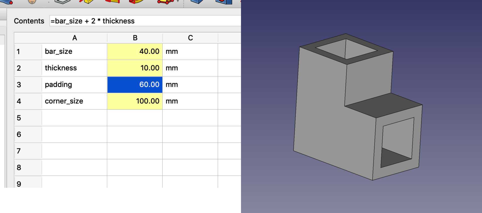
- The Padding will be equal to bar_size + 2 * thickness
- The total length of the corner piece is 2 * (bar_size + thickness)
Let’s change the constraint to the corner_size
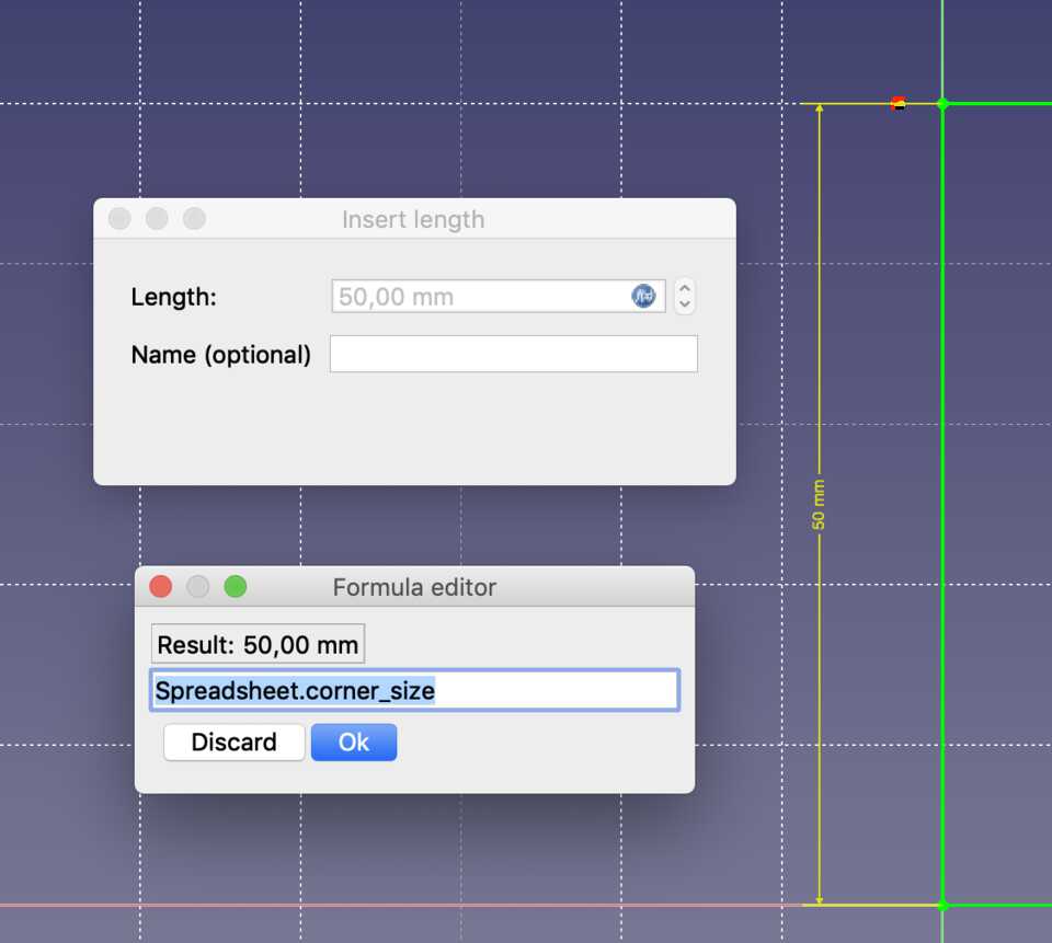
Finally the Padding to it’s corresponding variable.
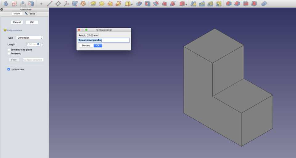
We have the padding, looking good.
Creating a sketch on the face
Let’s create a sketch on one of the two faces. It will use the dimensions from the Spreadsheet to create the Pocket. It has to have the size of the bar, and be centered in the middle of the face.
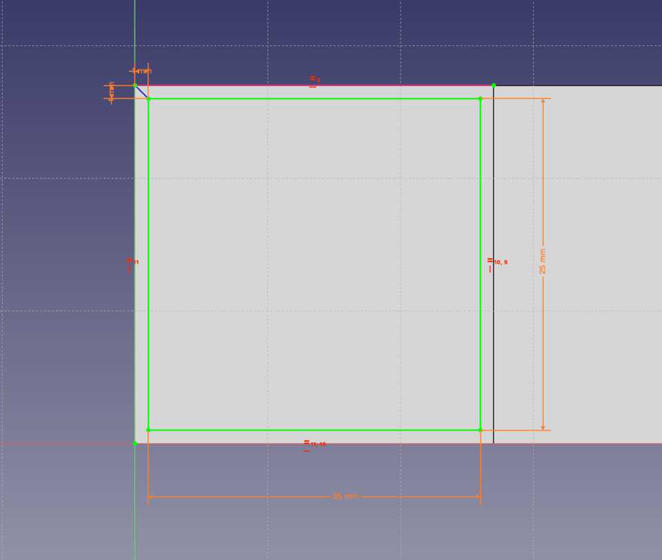
I created a square, and added a constraint so that the opposite edges are of the same length. Then I selected two edges and gave them a size constraint of bar_size.
Centering the sketch to the middle of the face
To center it to the middle I had to get a bit creative.
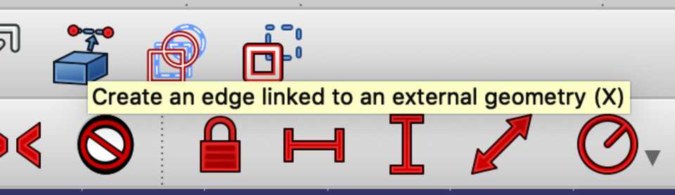
I used the Create an edge linked to an external geometry tool and copied the edge of the corner piece. It means I can now use this line and its vertices to use for snapping/aligning...
… and then snapped the point of the top left edge of the sketch with the left vertice of the created line.
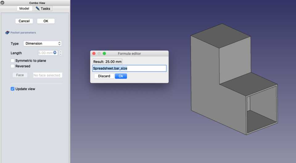
Next step is to use the Pocket tool the sketch and use the variable bar_size for the Dimension.
Copying the sketch on the other face
To create the same sketch on a new face I followed this page: https://forum.freecadweb.org/viewtopic.php?t=5433
I copied and pasted the Sketch001 into the project. It got renamed Sketch002.
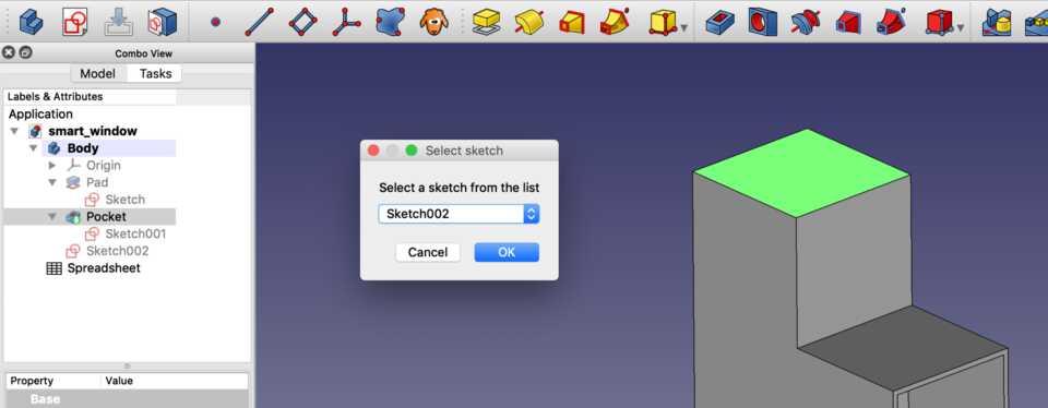
I selected the face that I want the sketch to copy to, and then clicked on the Map Sketch to Face tool. It prompted which Sketch I wanted to copy, and selected the corresponding one.
It copied the Sketch but to the wrong place, as it still had the constraints from the previous Sketch.
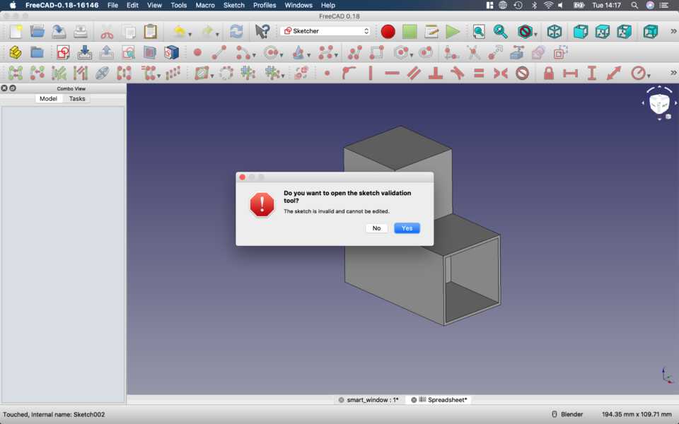
I closed the sketch, and then double-clicked Sketch002 again. It prompted me if I wanted to open the sketch validation tool. I clicked ok.
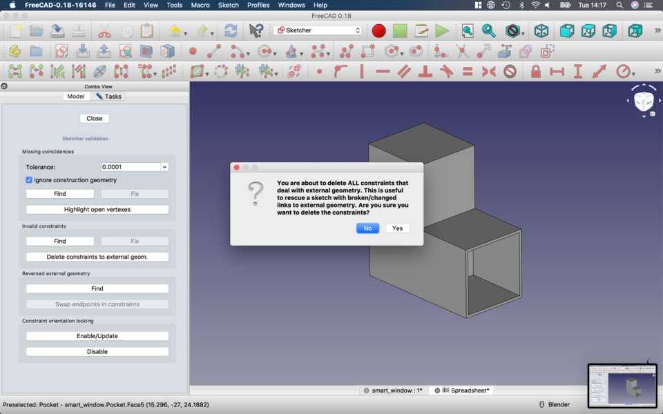
And then clicked Delete constraints to external geometry, so I could recreate it like in the previous steps.
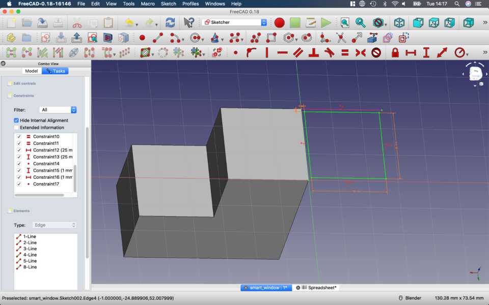
All the constraints are there, I just needed to re-center it, by using the Create an edge linked to an external geometry again.
The edge is created, I select the two vertices I want to constrain together and constrain them.
It’s all green, which means it’s happy, which means I’m happy.
Moment of truth, Pocket tool to the rescue once again. It works.
Playing with the variables in the Spreadsheet
I played around with the Spreadsheet values to see if it all worked, and it did.
Creating the bar
I don’t think I need to document this… you simply create a Sketch, make a square, constrains all sides to the same variable bar_size, use the Pad tool and extrude it to whichever length you want the bar to be (I created a new variable in the Spreadsheet for this).
Exporting both object to STL to animate and render in Blender
I chose to use Blender because it’s well made, open source, and especially good with animation and render.
Exporting is simple, simply click on the Body you want to export, File > Export, choose the STL format and ta-da!
I also exported them in STEP format to see what I can do with it in Blender.
Blender
Importing and preparing in Blender
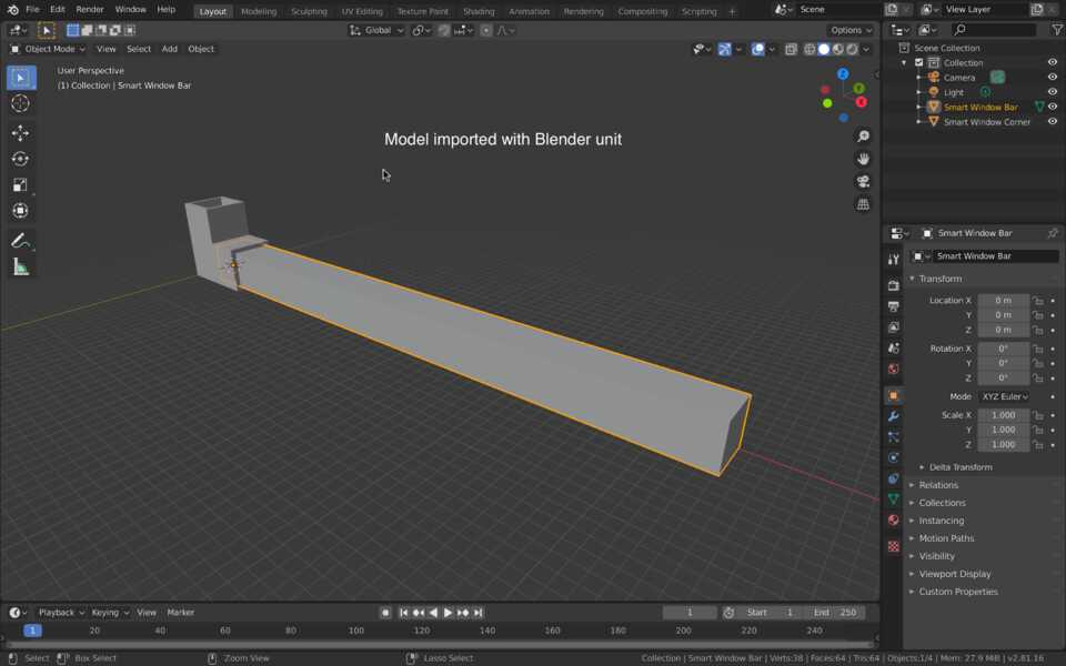
Model in FreeCAD, I exported both Body separately and then imported them in Blender.
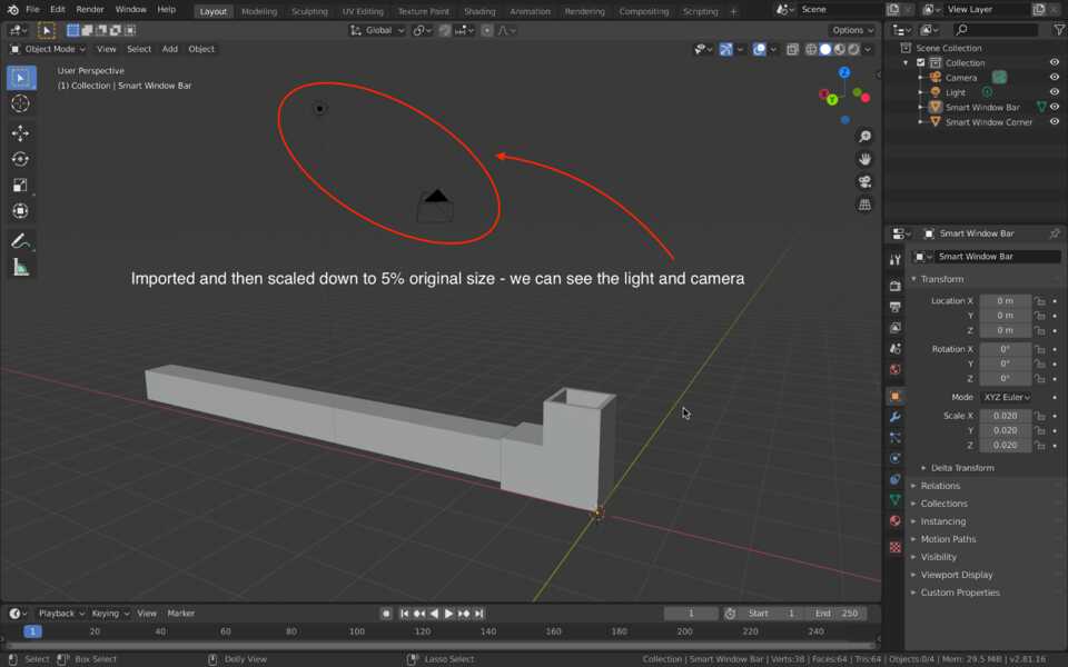
Had to scale it to 1% it’s original size for it to fit with the camera and light.
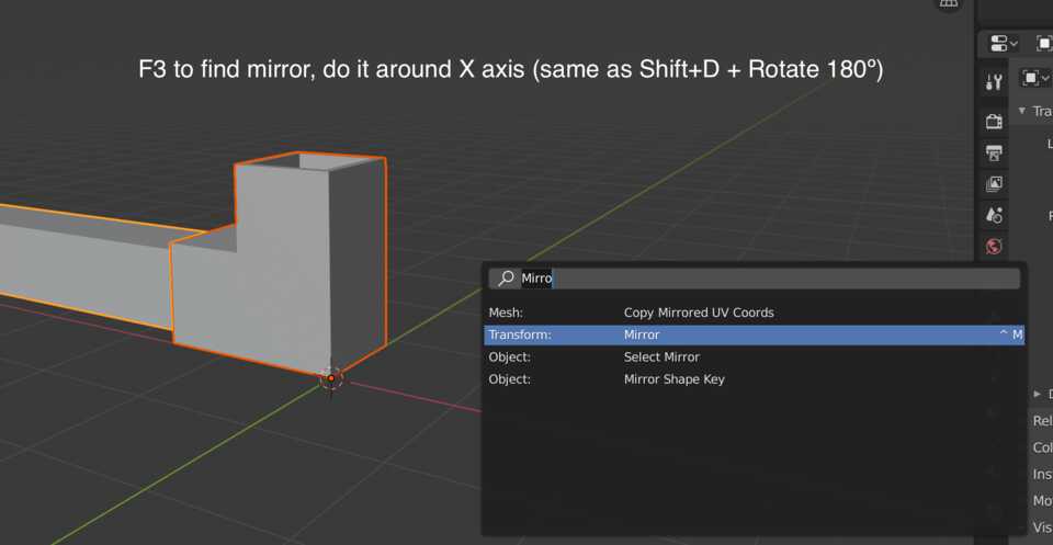
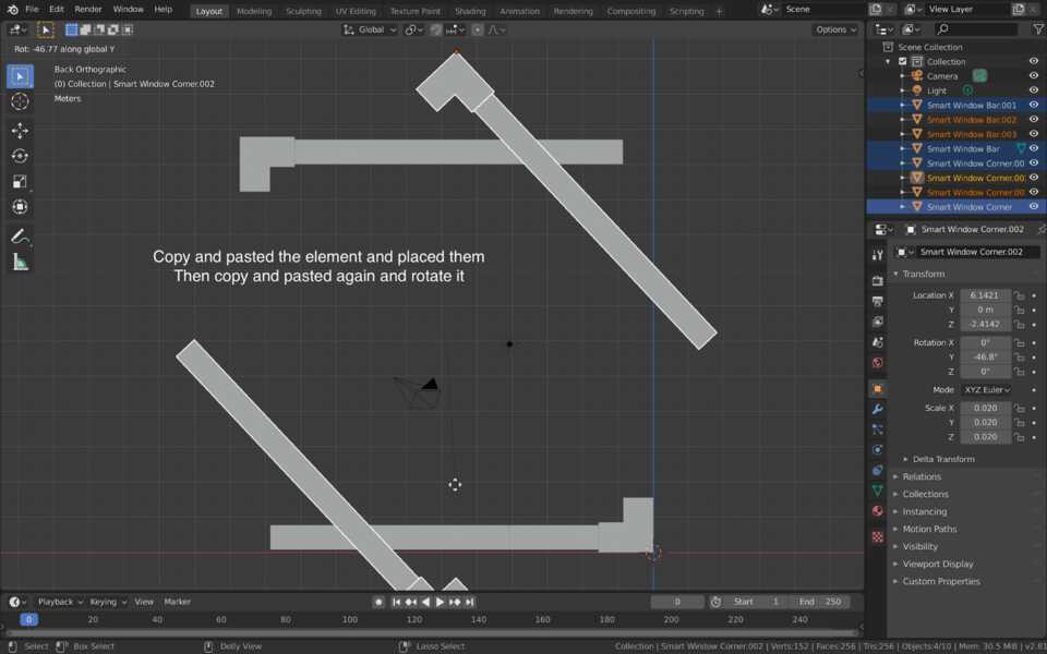
Duplicated the two objects (Shift + D), then used the Mirror tool around the Y axis (not X). then Grab tool (G) to move it up and to the left to give the results below.
Then selected all the geometries, Duplicated them again, and finally rotated them 90º so they all fit together.
Animating in Blender
For this assignment I decided to animate the camera, the light, and then the window frame itself.
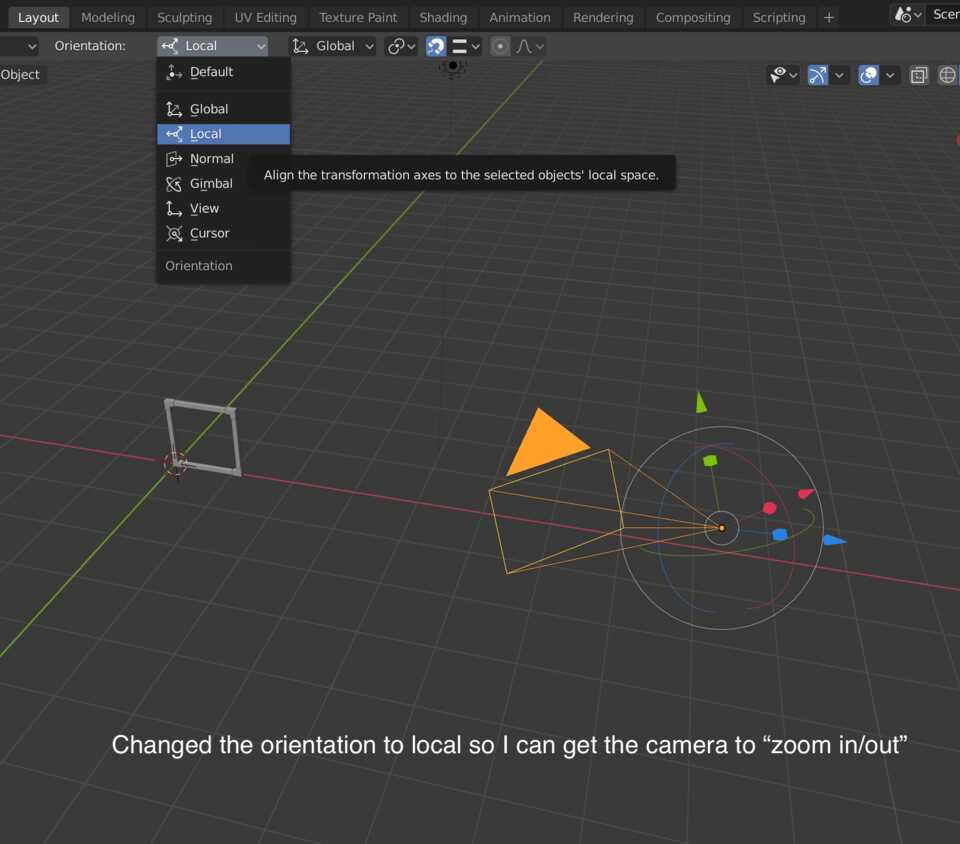
For ease of animating the camera I changed the Orientation of the Gizmo from Global to Local, so I could easily Move the camera in the axis it was pointing to.
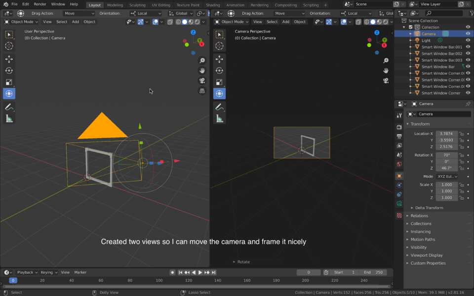
I split the view into two so that I can animate the properties of the Camera, in this case it’s Position, Rotation and even Field of View, and see what it looks like.
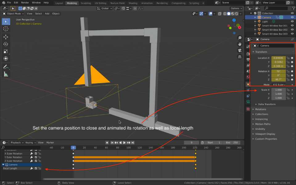
To animate, select the Object you want to Animate, put it at the first position you desire and the click on the dots on the right of the Property, that shall create a Keyframe.
Then simply Grab, Rotate, do whatever to your object, and Set these Keyframes again.
Using Materials in Blender
I started playing around in the Shader editor but quickly realised it’ll look bad, and just waste time.
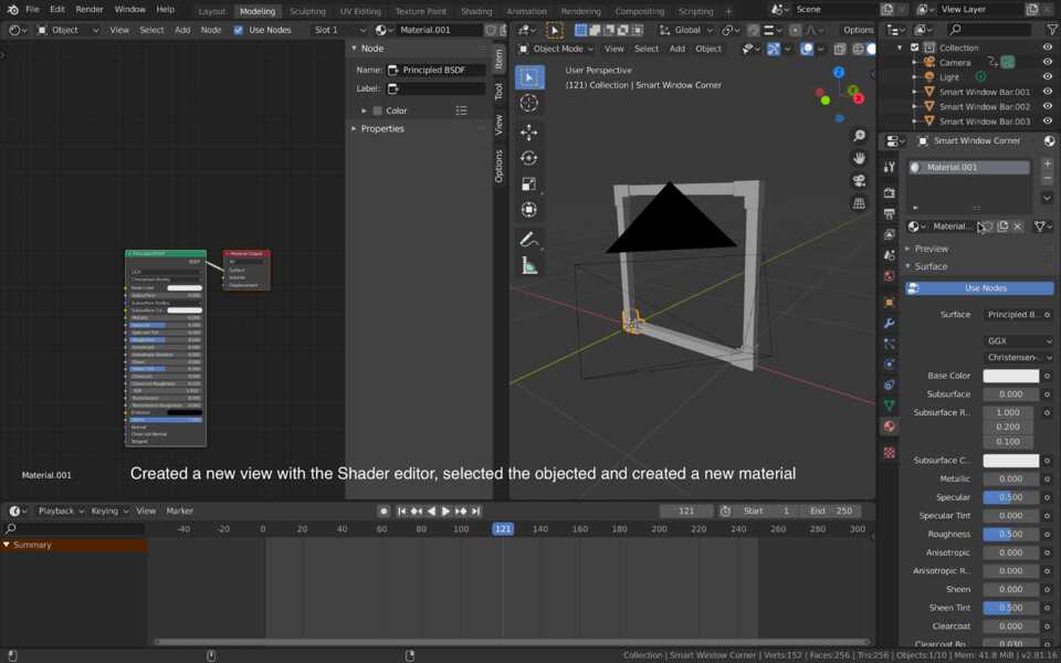
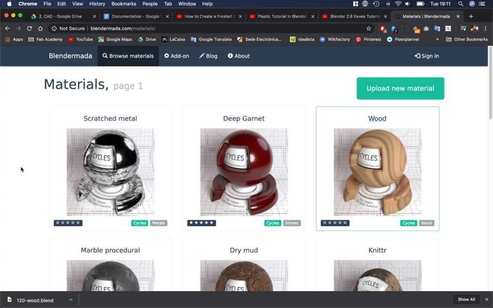
So I decided to find some Materials online. I found some ABS plastic for the corners and then some Wood material for the actual frame.
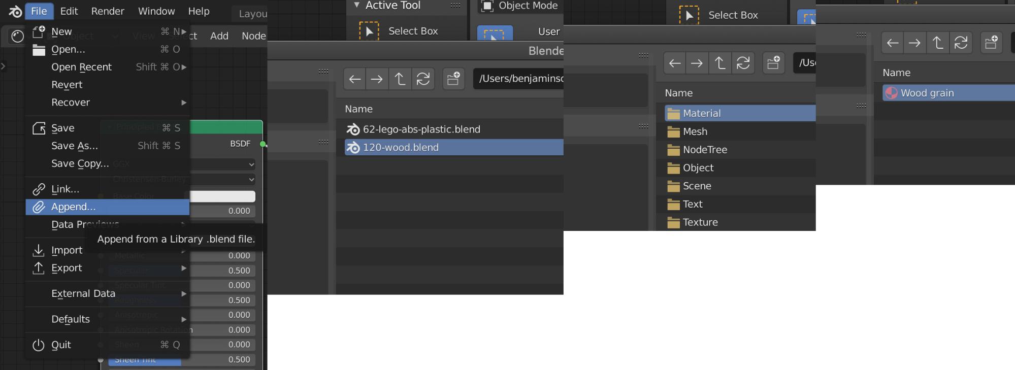
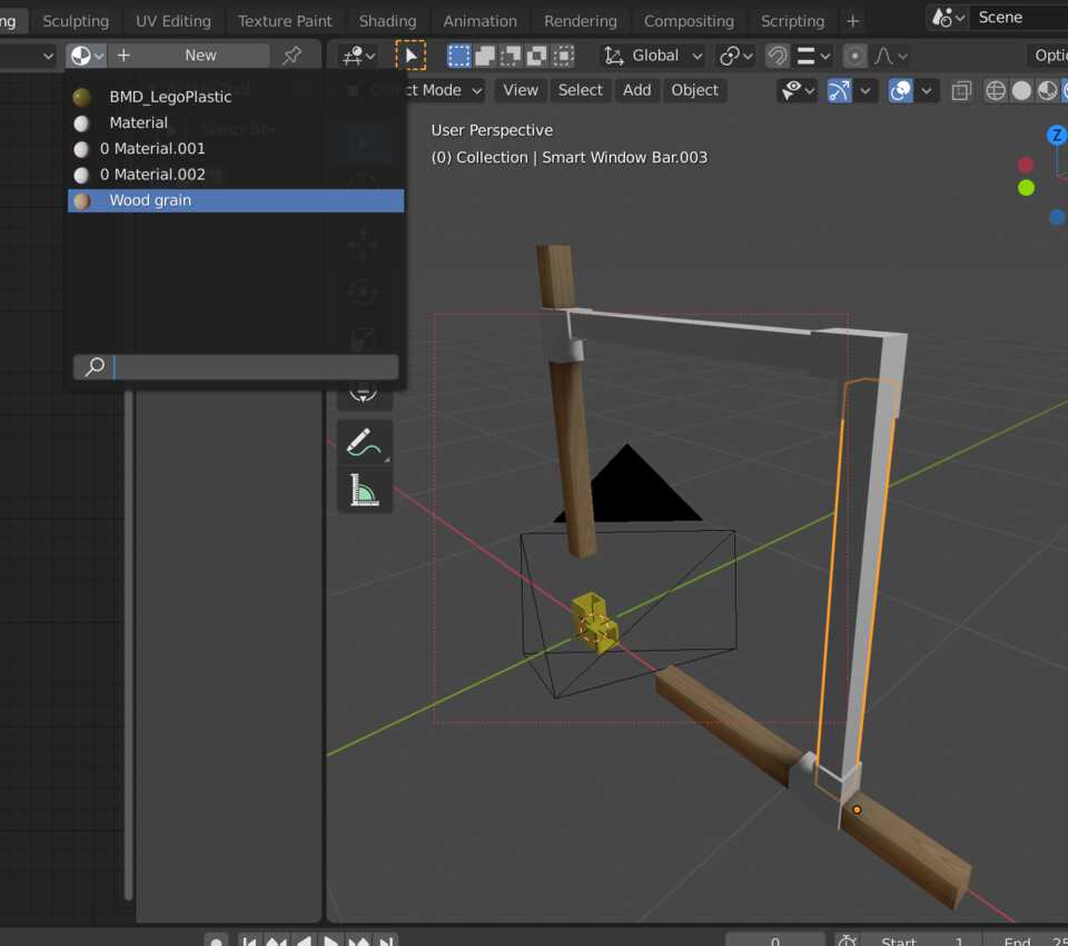
Then imported the Material by doing File > Append, then double-click the material, enter it’s Material folder and finally pick the Wood grain file. It adds it to the library of materials for Blender.
Then select the objects that need the corresponding Materials.
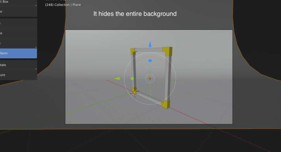
Preparing the scene for the Render
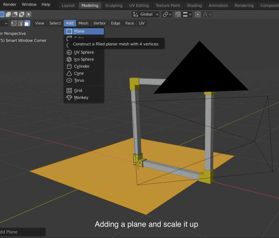
I add a Plane, Scaled it up to use it as a backdrop to my render. I rotated on the Z-axis so that it’s edges are parallel to the camera frame.
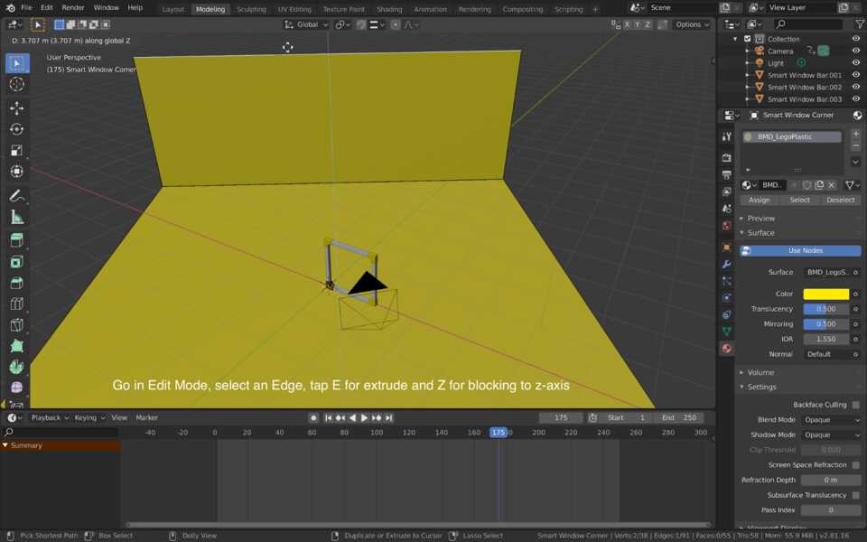
I switch to Edit Mode with the Tab key, use the Edge selection tool and select the Edge the furthest away from the camera, tap E for Extrude, Z to lock it to the Z-axis.
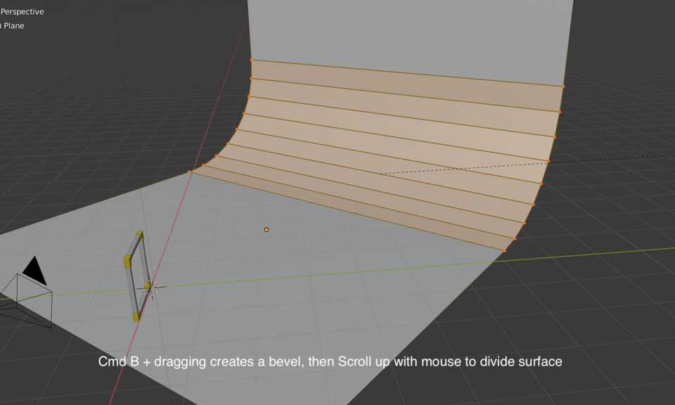
It’s a bit of a harsh corner, but fear not! Cmd + B enables the Bevel tool, then scroll-up with the mouse to create more subdivisions for a smoother bevel.
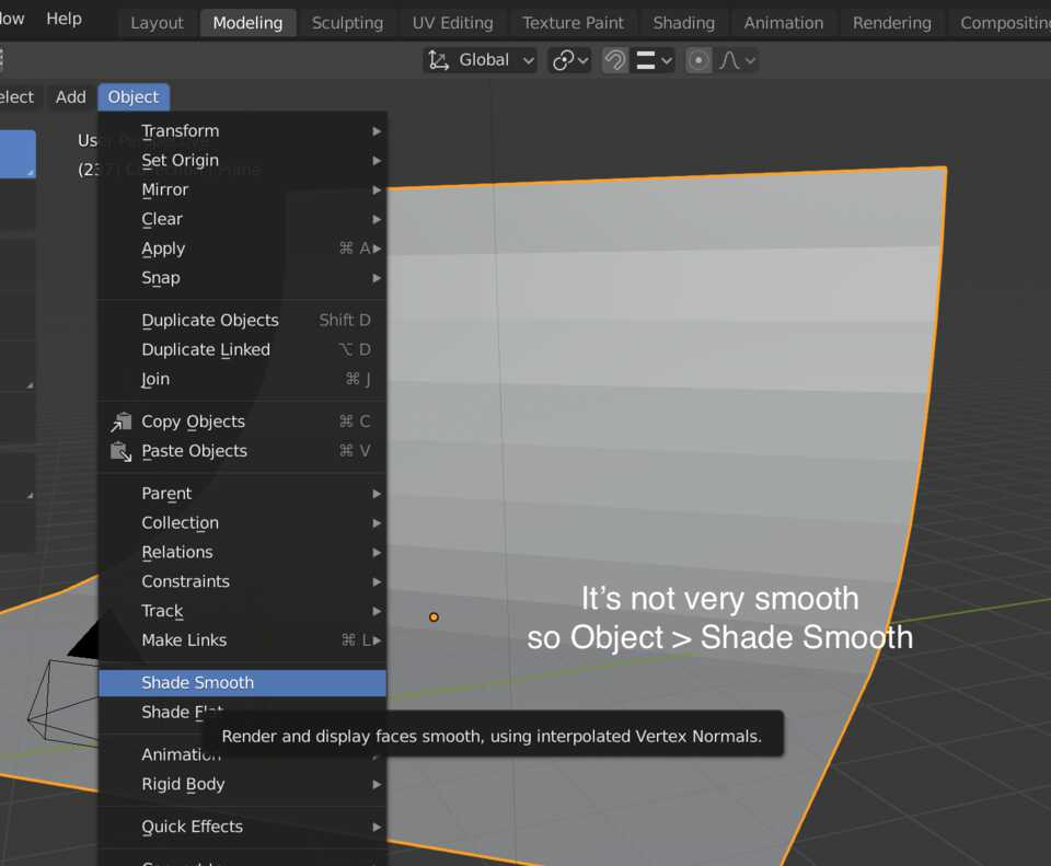
Still can see subdivisions, but check it out: Object > Shade Smooth, and boom, it smoothes.
Looking nice, ready to be rendered me think.
Rendering in Blender
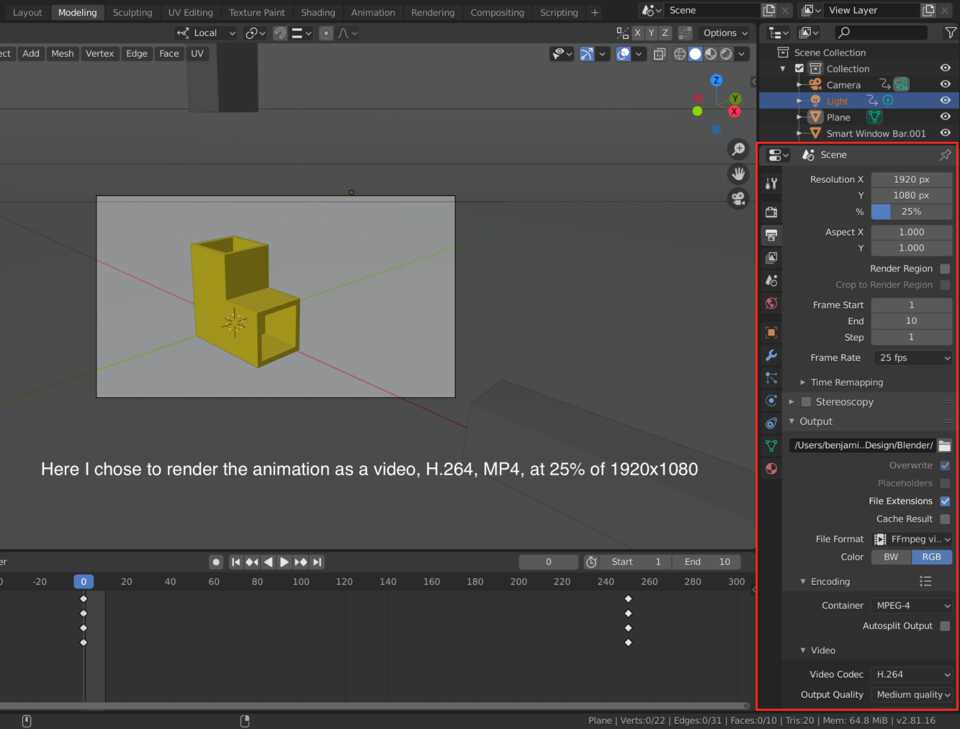
In the Editor Type window on the right, there’s an Output Properties tab. Here you can select the Dimensions, I tried with a Resolution of 25% at 64 Sampling, and then 50% at 128 sampling. The file size were 566KB and 1.2MB respectively.
I choose the FFmpeg exporter so that I can pick my own settings, in this case H.264 codec in an MP4 container.
In the Performance section I pick the option to Export using 14 Threads of the 16 available on my computer so that I could do this Documentation at the same time.
Here’s the final result.
Download the Blender filesHave you?
© Benjamin Scott. No rights reserved.