
17.
Machine Design
Assignments
group assignment
actuate and automate your machine
document the group project and your individual contribution
Overall
First of all, here's the link to our group documentation: Pong Machine page
For this week Antoine and I collaborated on every aspect of the machine. We started by thinking about what was needed to make the machine work. We then started building these pieces and testing them independently. When they all worked we put them all together.
Most of the project is an equal collaboration between Antoine and I.
-
If I had to divide the tasks I’d say Antoine:
- designed the acrylic panel to hold the NEMA motor
- designed the 3D printed piece to hold the solenoid
- soldered the wiring to the solenoid, end-stop and the extension from the motor to the cnc shield
- implemented all the logic for the coding that moves the motor to the right column when the ball crosses a line, calibration of the width of the board with the end-stop
-
On my side I:
- I researched how to detect the ball going over the line with capacitance and then by creating a short, and started the simple code
- designed and wired the metal strips detecting when the metal ball rolls over it with pull-down resistor
- cut the 10mm transparent acrylic that Antoine designed
- setup the wiring of the motor to the Arduino CNC shield and researched the free pins we could use for the lines
- built the rail and board holding the motor
The entire project has been documented on the Pong Machine page.
the basis of a working pong machineDetecting the position of the ball
What are the options?
There are multiple ways for the paddles to position themselves correctly to hit the ball.
Camera vision
The first solution that comes into mind is to use camera vision to see where the ball is on the field.
That would mean you’d have a camera above the board, analysing the position of the ball. We found this method to be a bit overkill as you’d need to have quite a powerful device to do the calculations, at least a Raspberry pi, and it wouldn’t be visually pleasing. It would be nice to have a sleek looking standalone machine.
Capacitance
We then thought of having lines of conductive material across the board, and use capacitance to detect when the ball crosses over a line. We did some tests but discovered that the metal ball we were using wasn’t detected with the Touch pins of the ESP-32. We realised that capacitance works when an object has the capacity to absorb or emit energy. A metal ball rolling around doesn’t have that capacity.
There’s a lot of not very conclusive documentation here.
Creating shorts
We then thought that if we had two thin lines of conductive material, then when the metal ball rolls over them it would create a short that would be detectable. For this an Arduino would be enough as it’s just a matter of detecting voltage. We did some tests and we could easily detect the passage of the ball, even at hight speed. Good.
Creating shorts
Schematics of the circuit
The circuit is pretty simple. We feed one strip of copper some voltage, in our case we are using 3V3, and the other strip is connected to an input in the Arduino which acts as ground.
We read the input of the pin at all times and when the ball closes the circuit, the pin is pulled up, it reads as HIGH, and we know the ball has passed.
The problem was, it would work once, but then the value floated between 0 and 1 (or LOW and HIGH) in the Serial monitor... The voltage doesn't automatically go back down to 0, which makes sense really, there's no reason to... cue the PULL-DOWN RESISTOR.
We added a pull-down resistor between the input pin and GND. The main job of that resistor is that when the circuit is closed, rather than the current going straight to GND, it is being "blocked" and the current decides to go to the easier option, the input pin.
When the circuit ISN'T closed though, the input pin is connected to GND, and any floating voltage escapes through there. In another words, the voltage on the input pin is being pulled-down.
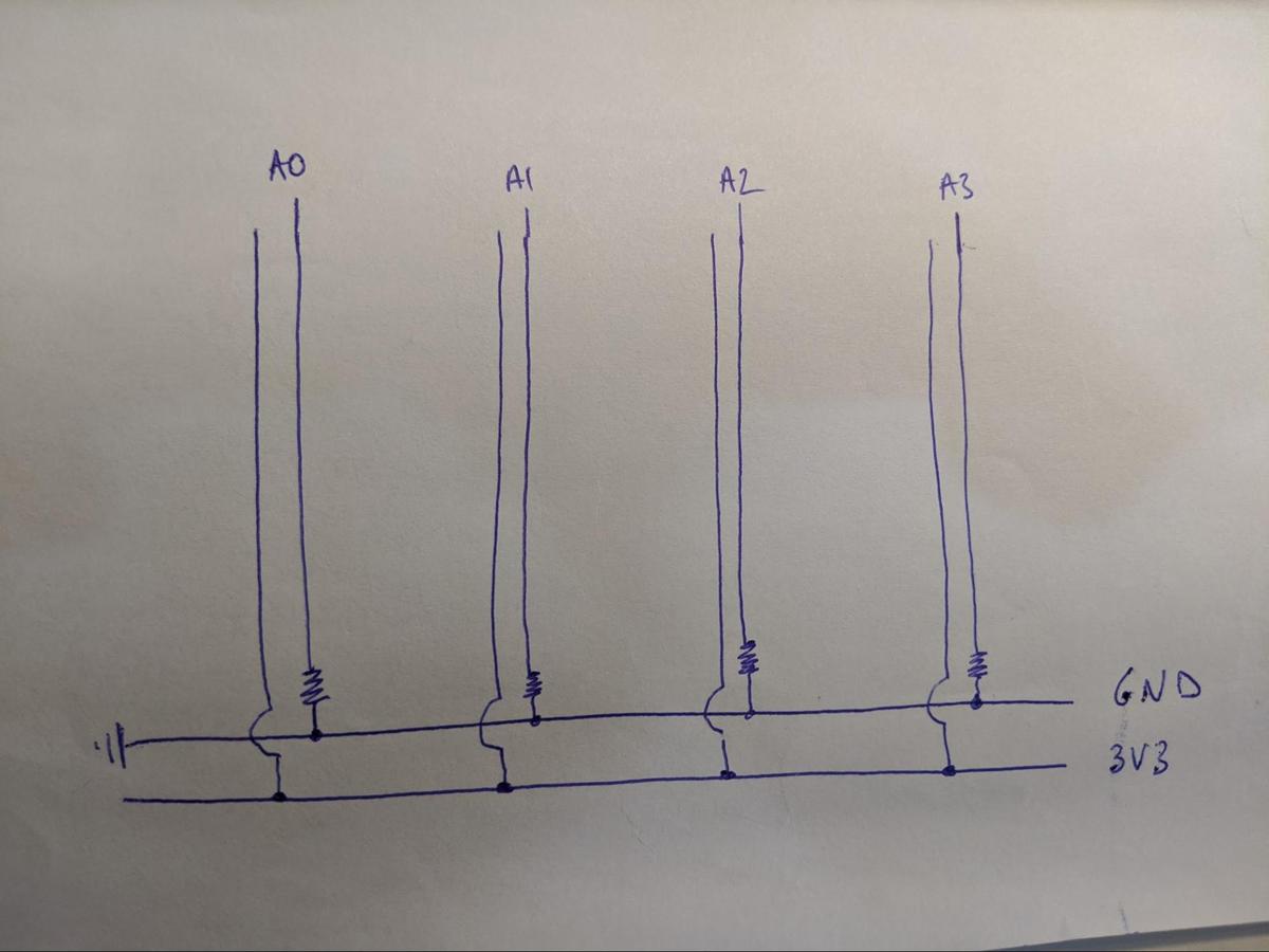
We know have the design, let's build it.
Building the circuit
We had first tested with copper lines, but thought the result wasn't great. It didn't seem to want to detect the ball as often as we wanted. We blamed it on the fact that maybe it had a thin layer of oil on top which offered resistance.
Because of that, we tried with aluminium foil, and it seemed like the detection was much better. We continued working with aluminium, and even made our own aluminium strips by using double-sided tape.
The problem occured when we tried to wire everything together. You can't solder aluminium, so instead we tried using glue. It worked, but it would easily disconnect, the aluminium was quite fragile as it was super thin, and problems over problems arised.
We noticed that having a delay in the loop() function made the detection of the ball less sensitive, which makes sense. The tangent of the ball connecting the two lines is probably only in contact for a fraction of second. If we are waiting 20ms between each reading, it's possible the ball has already crossed. We completely removed the delay function and noticed better results
Due to the faulty connections with the aluminium, we decided to go back to the copper tape, as we can solder straight onto it, assuring much safer connections.
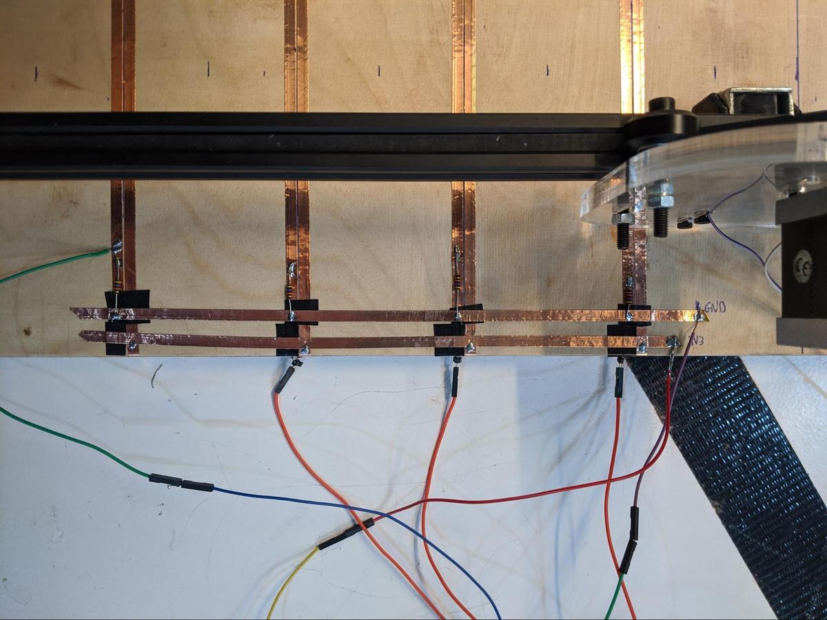
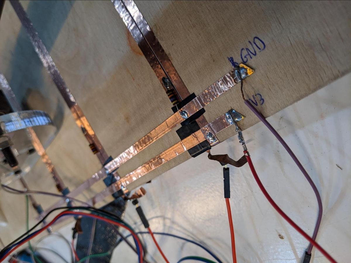
The copper tape being conductive on both sides, I put some insulating tape under to make sure there are no (undesired) shorts
Simple code to detect when the ball crosses to another column
Here’s the code we used at first to detect the passage of the ball. It's super simple.
#define inputPin 22

void setup() {
  Serial.begin(115200);
  delay(1000);
  pinMode(inputPin, INPUT);
}

void loop() {
  const int value = digitalRead(inputPin);
  Serial.println(value);
  delay(20);
}
Basically it reads the digital reading of the pin. Thanks to a pull-down resistor it is always 0 (LOW), unless the current goes through, which means it is 1 (HIGH).
How many columns can we have?
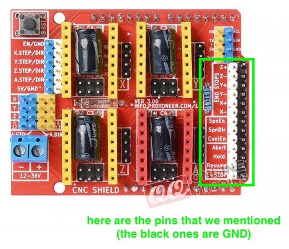
The Arduino Shield to control the NEMA connects to all the pins of the Arduino, but not all pins are being used.
CNC Shield V3 for Arduino UNO - Stepper Motor Controller
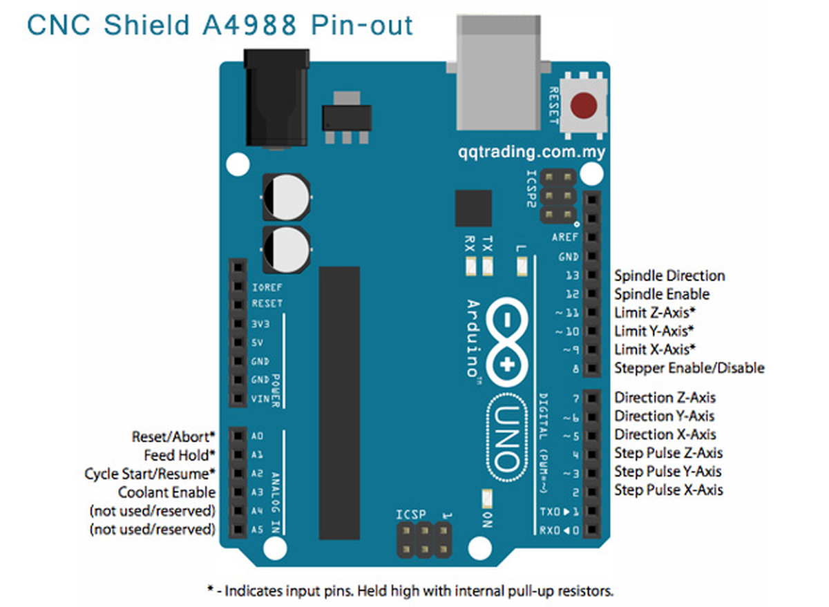
For controlling the two axises we’ll use the pins Direction Y-Axis, Direction X-Axis, Step Pulse Y-Axis & Step pulse X-Axis, in other words (or numbers), we’ll use pin 6, 5, 3 and 2.
We’ll also use Limit X-Axis and Y-Axis, so pin 9 and 10.
We won’t use a spindle, so pins 13 and 12 are free. We won’t use the Z-axis so pin 11 and 4 are also free. We won’t use Reset/Abort, Feed Hold, Cycle Start/Resume and Coolant Enable, so pin A0 to A3. There are two other pins shown as (not used/reserved), pins A4 and A5.
In summary the free pins are:
- 4, 7, 11, 12, 13
- A0, A1, A2, A3, A4 & A5
A total of 11 pins are free. We only need one by line, we are using 4 lines for now.
Making the board
In order to make the board, we had to:
- Design and laser cut an acrylic sheet with the imprints of our elements (NEMA17 stepper motor and solenoid)
- Design and 3D print a support for the solenoid, so that it can be fixed on our mounting plate
- 3D print structural elements to make the rails stand upright
- Prepare and assemble the electronics (cables)
- Glue stops at both ends to prevent excessive movement
- Cut and position the conductive lines from a copper sheet
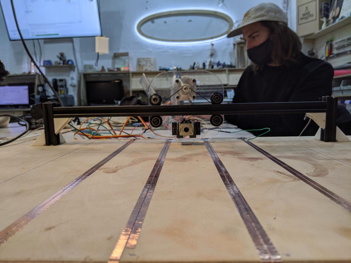
Making the rails
We decided to use the design where the belt is fixed to the rail and the motor moves itself along it. A future version could have the motor under or on the side of the board so it has less weight to move around. It could also be hidden for maximal minimal design (oxymore).
For most if not all of the build the screws used are M3s, more or less long.
We 3D printed some corner pieces we found in Thingiverse to attach the rails together. I modified them in Rhino by doing MeshToNURB and then boolean differenced one piece of the rail slide so it could sit flat on the plank of wood to keep it stable.

Antoine designed a plaque to hold the NEMA, the solenoid and the wheels.
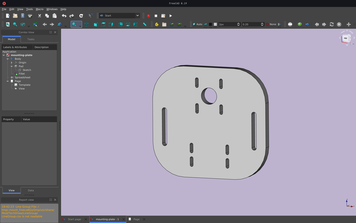
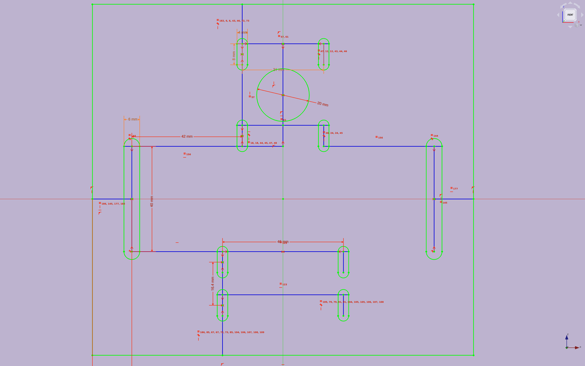
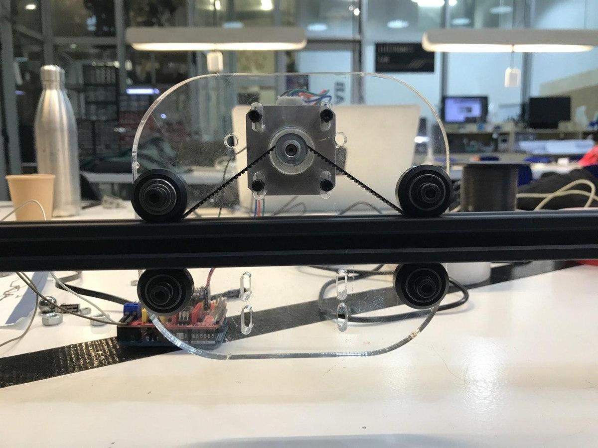
We laser cut the plaque in some 10mm transparent acrylic for maximum sturdiness. We struggled laser cutting that acrylic as flames appeared quite often when doing tests. We ended up using a power of 85 and a speed of 0.17, and kept the frequency at 20,000Hz.
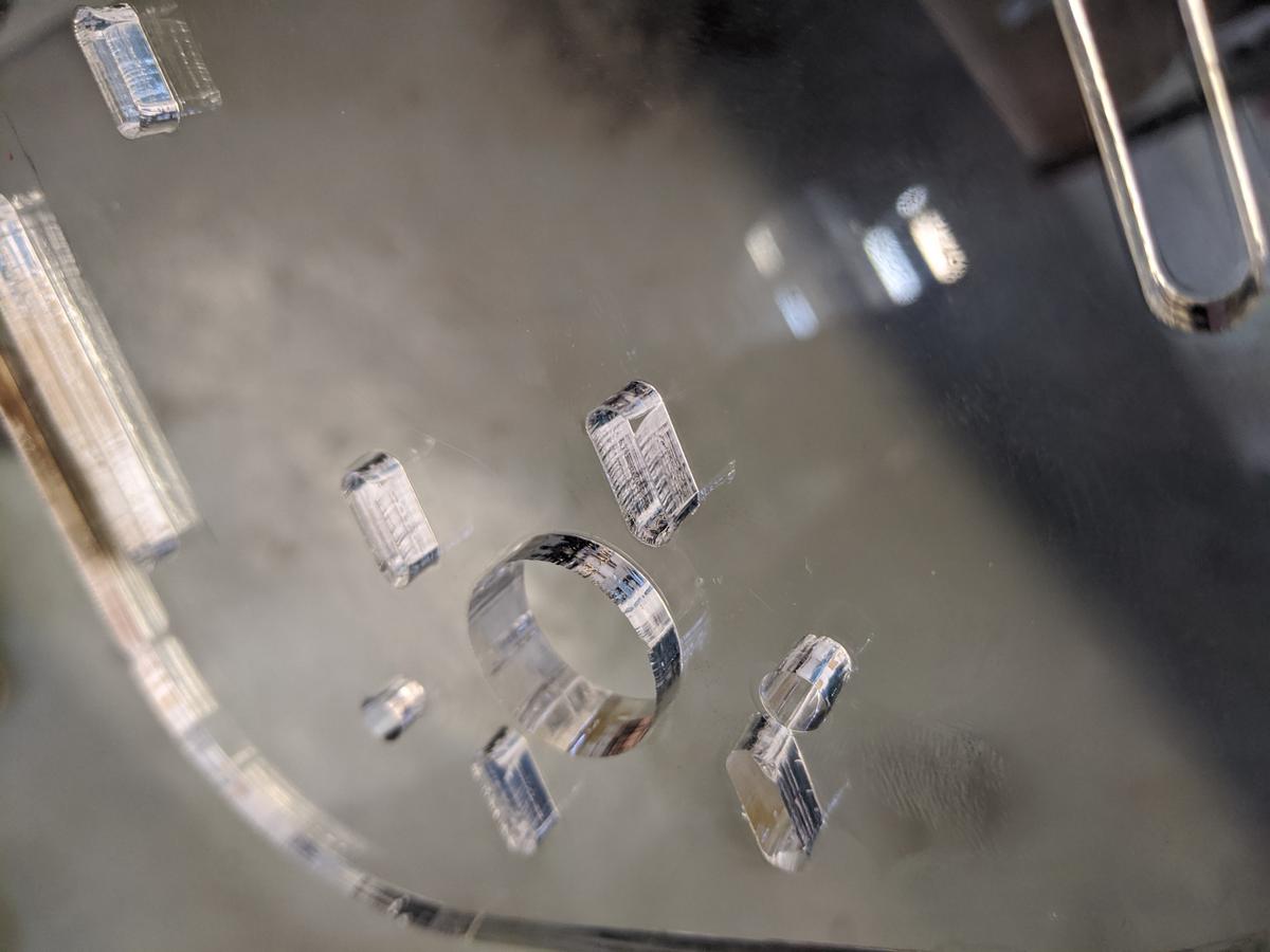
Somebody online advised to put the Z-offset to -0.10, which I guess is because of the thickness of the material to avoid that curve we can see further below.
you can see the curve in the laser beam where the laser ended at the start of the curves (see the ellipse-rectangle at the top left of the circle.
Looking back it could easily be done in 5mm acrylic, the plaque doesn’t need to be as sturdy as we thought.
It’s moving!
For the rest of the, and more complete, documentation please head to our Pong Machine documentation.