This week's group assignment is about how to use the test equipment in order to test/debug/understand electronic circuits. Because of the covid-19 situtation, I did this assignment alone, from my home.
Multimeter
A useful resource to understand how to use a multimeter is this tutorial from Sparkfun. It covers all the basics we should know.
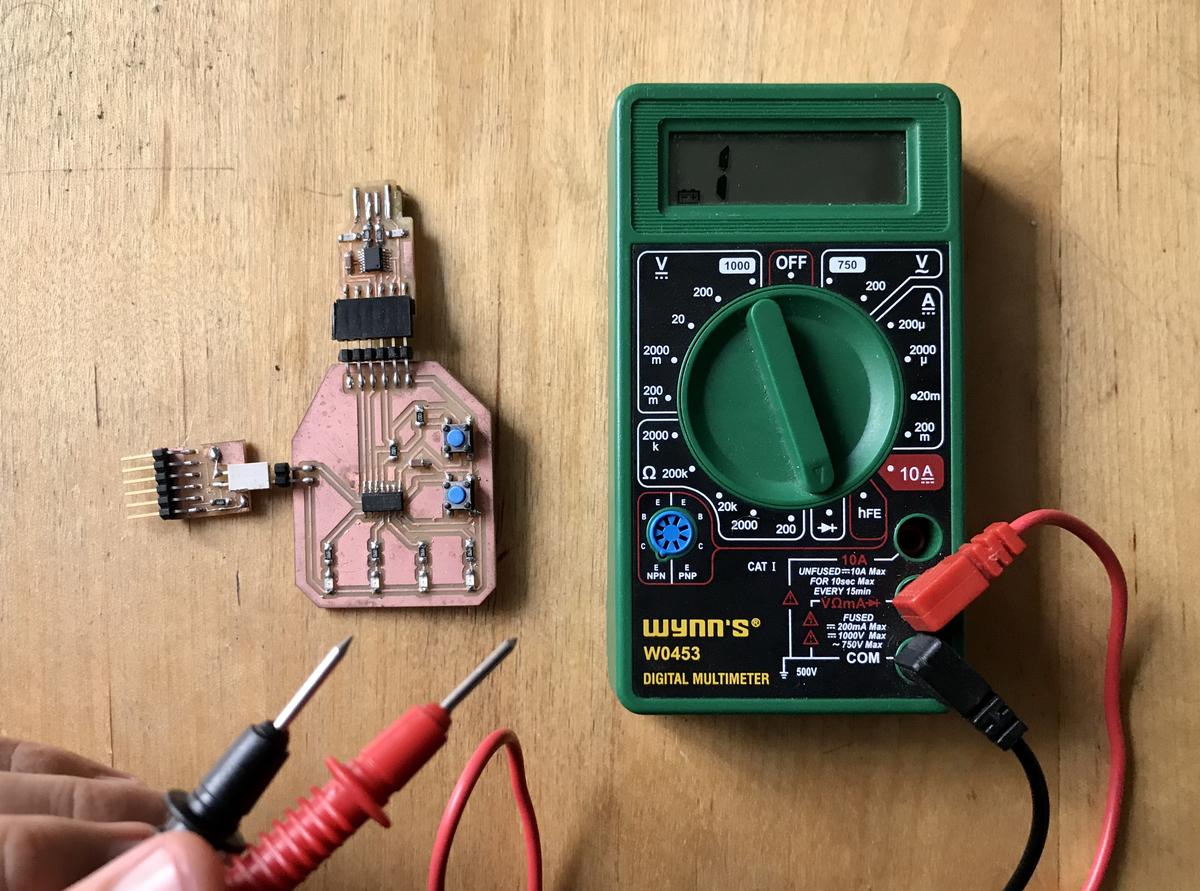
The selection knob allows to set the multimeter to read different things such as milliamps (mA) of current, voltage (V) and resistance (Ω). The different positions of a multimeter are there to adjust the scale, depending on the values you are measuring.
Voltage & resistance
Voltage and resistance can be measured the same way, as they both required to be measured in parallel.
Set the multimeter to the appropriate (voltage (V) or resistance (Ω)) function. Connect the black probe to the ground (-) and the red probe to power (+). This should give you the voltage pr resistance of the circuit. If you measure it the other way around, you'll get the opposite values (negative).
Current
Measuring current requires to connect the multimeter in the circuit, not only in parallel but in series. The current has to go through the multimeter in order to be measured.
Interupt your circuit with the two probes of the multimeter, set it to the current function (A) and you'll get the value you're looking for.
Continuity
Continuity testing is the act of testing the resistance between two points. If there is very low resistance (less than a few Ωs), the two points are connected electrically, and a tone is emitted. If there is more than a few Ωs of resistance, than the circuit is open, and no tone is emitted.
This is super useful when testing a freshly milled PCB, to ensure that all paths have been cut as they should be, that there is no short in the circuit. Or later, that the components are properly soldered.