WildCard (WEEK 17)
Individual assignment:
Design and produce something with a digital fabrication process (incorporating computer-aided design and manufacturing) not covered in another assignment, documenting the requirements that your assignment meets, and including everything necessary to reproduce it. Possibilities include but are not limited to wildcard week examples.After thinking about the availaible possibilites we found that learning PLASMA CUTTING will be good for this week. We haave used laser cutter in the previous assignments and it has its own limitations like the laser we have is not suitable for metal cutting operation. So we chose to work on the Plasma Cutter this week.
IMPORTANT NOTE : ALL OF MY IMAGES ARE POP UP IMAGES , IF YOU HAVE ANY PROBLEM READINGS THOSE IMAGES , PLEASE CLICK ON THEM AND THEY WILL ENLARGE AUTOMATICALLY AND YOU CAN READ THEM EASILY
Machine Used
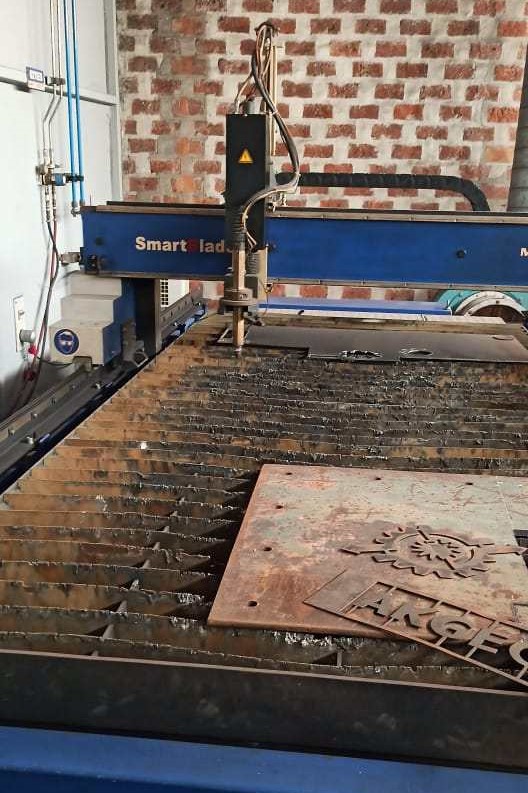
Messer Cutting Systems Smart Blade
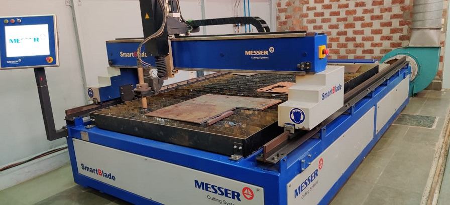
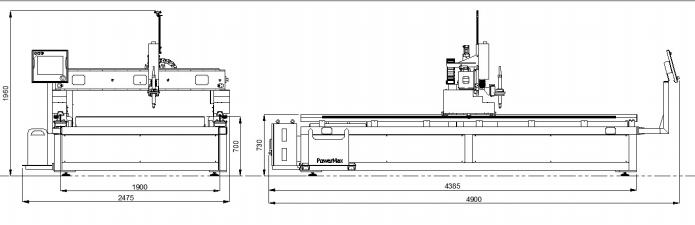
Basic specification of the machine
If you are not familiar with what is plasma cutting , please go through this video
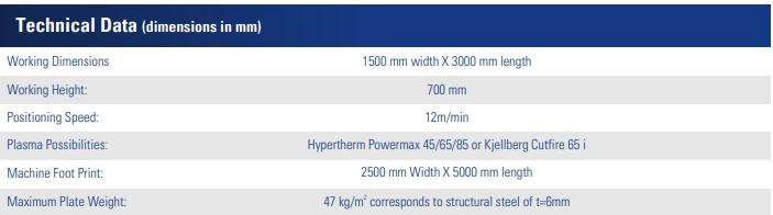
Starting up with machine
Once you reached the machine you can see these buttons on the touch panel , rotate the black one clockwise , its for starting up the machine
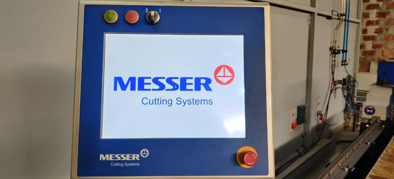
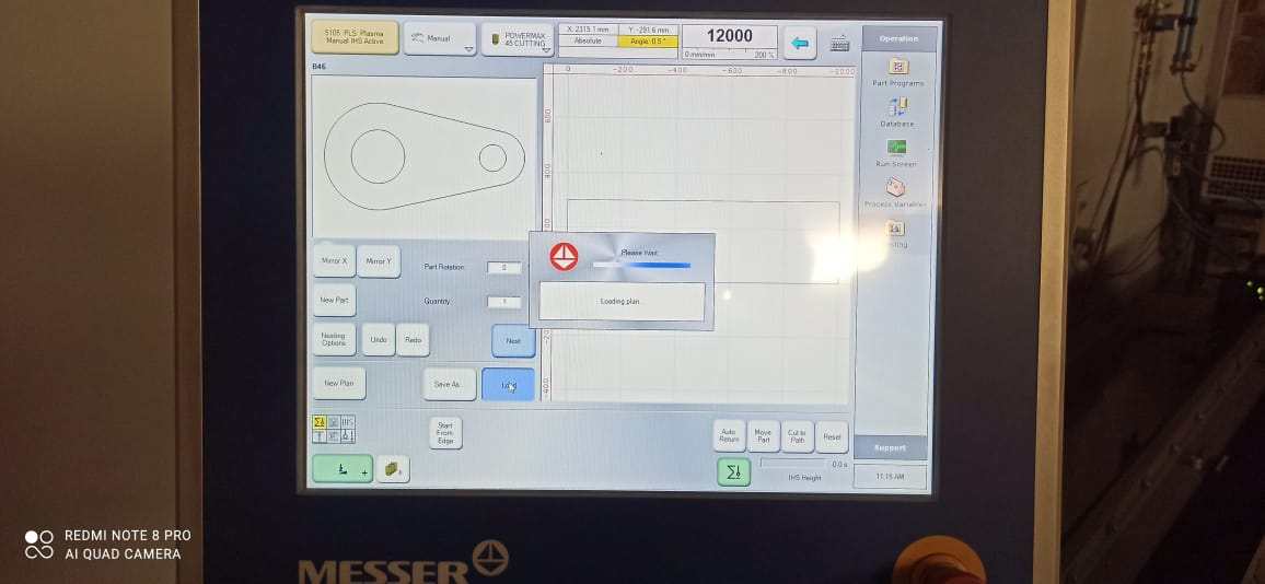
Software is starting up
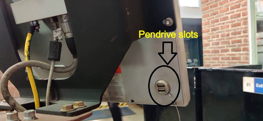
Machine has 2 inbuilt pendrive slots on the back of machine for transfering the file to the system
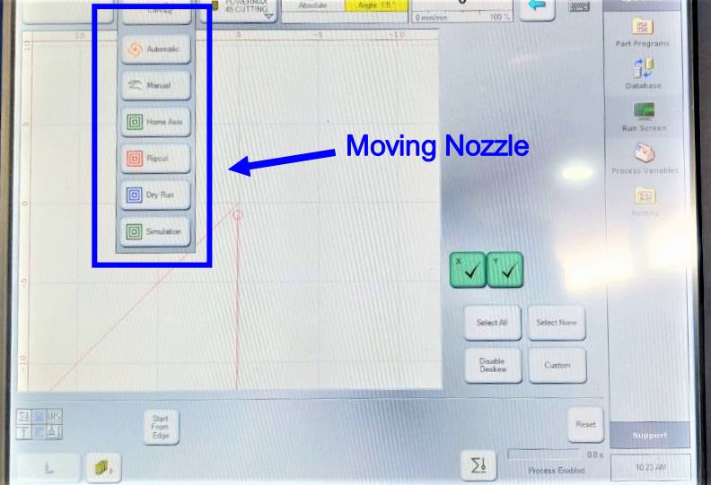
The first menu control the nozzle and its working
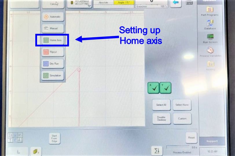
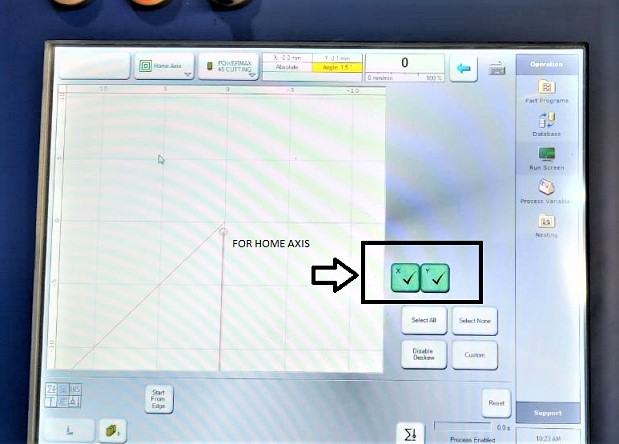
First step is to setting up the home position, so please click on the 3 option i.e. "HOME AXIS"
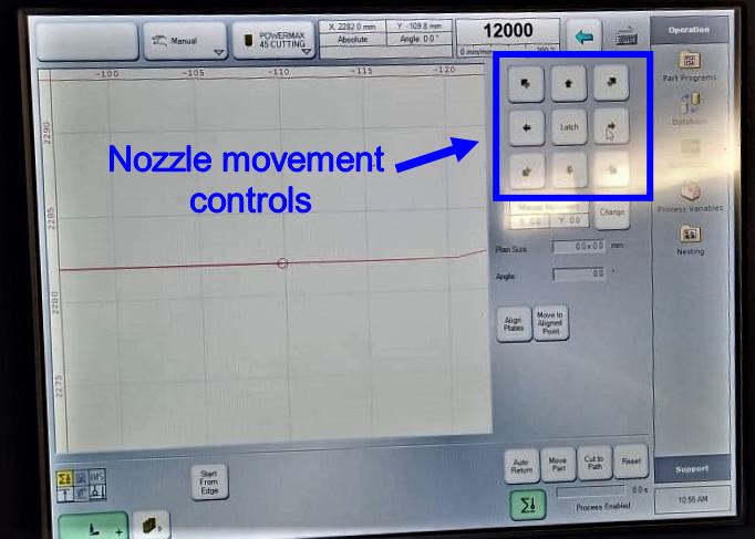
These are control for Nozzle movement and you require to move the nozzle to set the home axis , please move the nozzle towards metal sheet
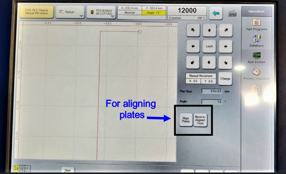
Now you required to allign the nozzle according to the metal sheet , because some times when we place the metal sheet on the bed , it can be misaligned and once the sheet is placed on the bed it is to heavy to move again and alligned , so we require to allign the nozzle according to how metal sheet is placed
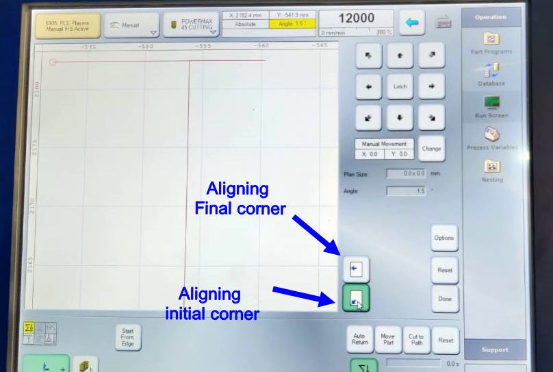
For perfect alligning you are required to give to corners , one is the initial point and second one is the final corner , once you give both corner , the machine will understand how the plate is alligned
Once the X and Y directions are alligned , now you require to allign the Z direction
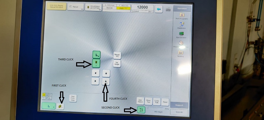
This process is comparetively easy as machine will automatically allign itsself you need to follow these 4 steps
Pls watch this video , this will show you exactly what you required to do
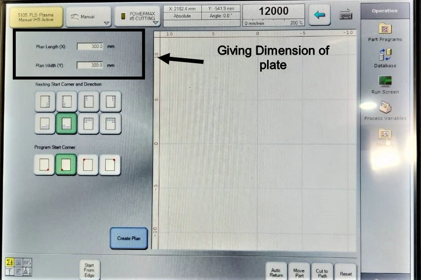
Now all the X-Y-Z alligning is done , we rquire to give the dimension of the plate we are working with , in our case its 300 X 300 mm
We have given that work are
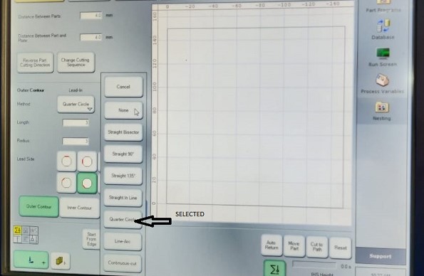
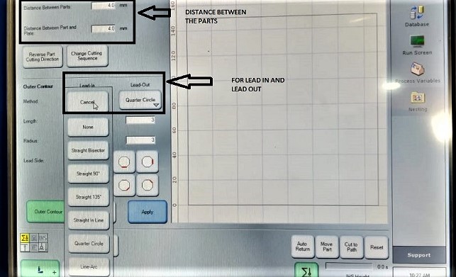
Then we require to providean inner contour and outer contour and lead in and lead out. These are the extra distance which the nozzle travel apart from the design. Because when if the nozzle starts from the design point then the cut is not complete so we need to give it extra contour on inner and outer side. for lead ion and out we have selected quater circle but we could have used the other ones also.
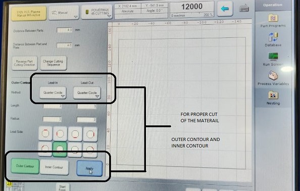
there are several oprions given for countour and types of lead but our instructor suggested that we should stick with quator circl e, as it is the best option
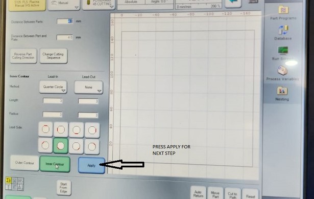
click on the of APPLY option for the next step.

It will guide you to the option on which , it will ask you to upload the file which is required to be cut
Group assignment
We require to have test cut before we can starts cutting our designed piece
Test 1
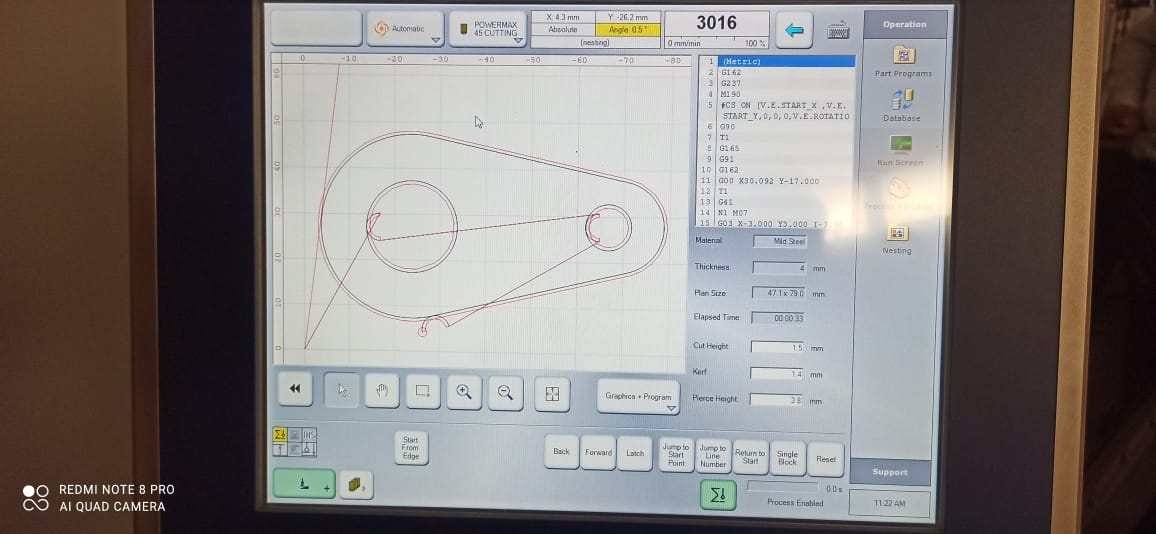
This is the test cut we did on the mild steel sheet of 4mm thickness. The feed rate varies accordingly with the thickness of the sheet . In our case the feed rate is 3106mm/min.
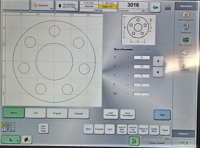
For this test we chose this circle as a test piece
Added that drawing to the 300mm X 300mm plate which we previously created and then load the image
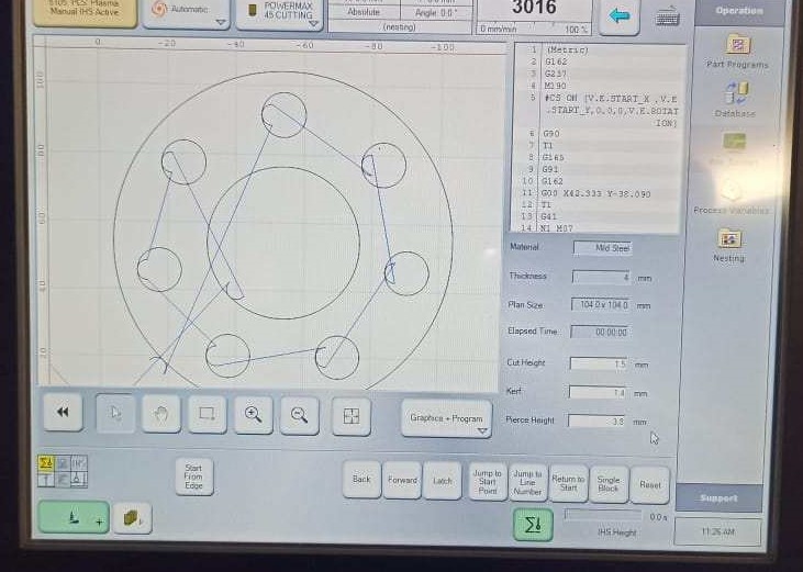
The machine is realy smart and it automatically generate the tool path and how machine will move , as well as machine has an inbuilt kerf calculating program , which when we provide the material thickness and type of material the machine automatically generate the kerf for out piece as well as cutting speed , so it was like plug and play
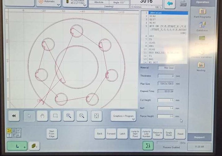
Machine has generated G-Code on his own for it swoking
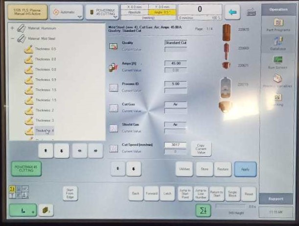
Below every material you can see the thicknesss of the sheet and for every thvikness the nozzle adjusts its power and it cuts the sheet through.
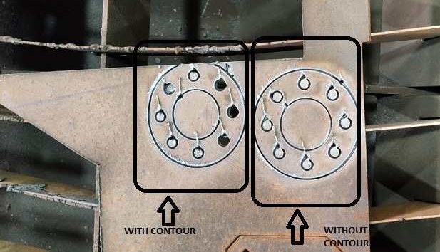
To know about importance of countour , we cut 1 piece without giving any contour and 1 with both inner and outer contour
Video of plasma cutting the piece
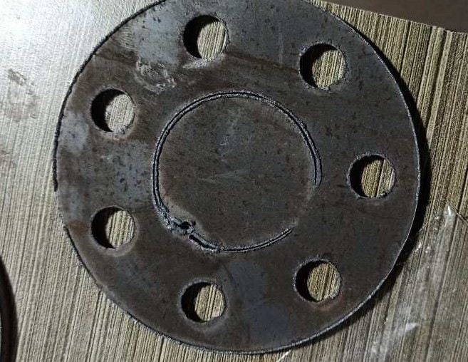
As you can see this image shows that without contour the pieces which were suppose to cu out were not able to come out
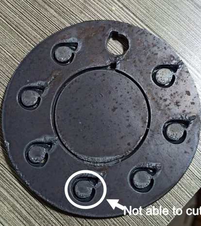
This is this back side of the same non -contour piece the part didnt get cut rather it's like it welded again by the heat
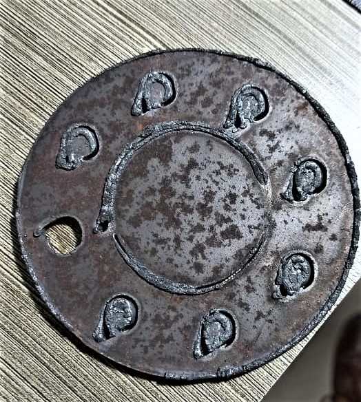
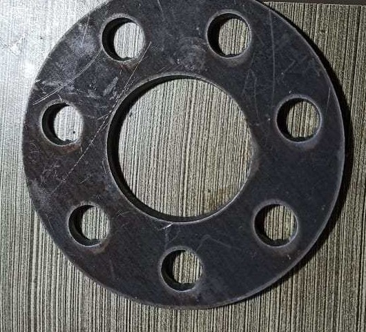
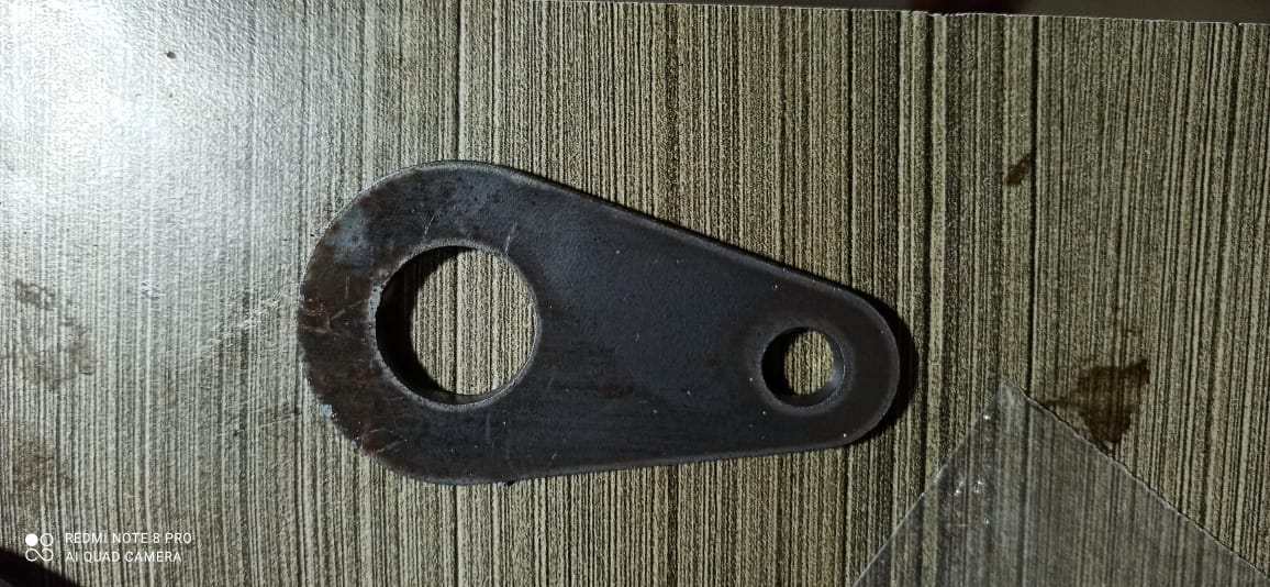
This image is far better it has all the holes cutted out , but it lacks finish as our instructor told us that the nozzel which is fitted in the machine is old and not able to hgve super finish rather we got only average finsh
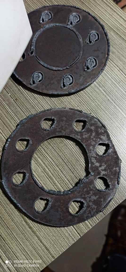
This image shows how much bur we got on the back side
Outer Contour and Inner contour
We always want out piece to be neat and clean and without any error in the dimensions and also want that it comes out very easily out of the matetrial stock when cut. All these properties are achieved when we provide inner and outer contour with lead in adn lead out. Outer contour is when we want to cut a circle and the circle will satrt to cut from a point away from the designed circle. The point where the cut will start will be determined by the value of Lead in and the point where the cut will stop will be detrmined by the lead out value.
Lead in and Lead out
The lead in and lead out are used for the motion of the plasma nozzle. If we want to cut a hole in a piece then we have to provide lead in and lead out at the inner contour. Inner contour means that the inner portion
is not of our use and the periphery of the hole will come out clean.
The lead-in and lead out for the outer contour is used if the blank is of our use. For the blank we have to give the Lead in and lead out at the outer contour. The outer contour facilitates perfect blank.
In the test piece Number 1, toolpath was made such that there was no Inner contour. But outer contour was given for lead in only and lead out was not given for outer counter.
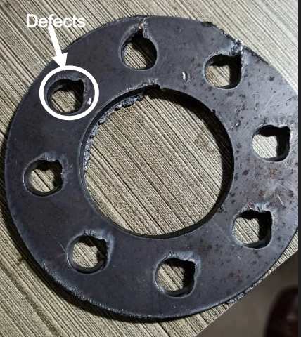
In the test piece 2, LEAD in and LEAD out was given and then we could see the difference that the cut was very proper and easy removable. The holes at the periphery were cut with the outer counter and lead
in and lead out beacuse of which the shape of the hole is distorted. The holes would have come perfectly if the holes had inner contour with lead in and lead out in it.
Test 2
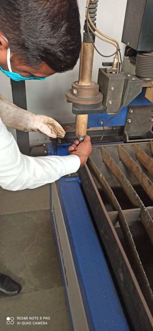
Before we can move to second test our lab instructor suggested us that we should change the nozzle for beeter result
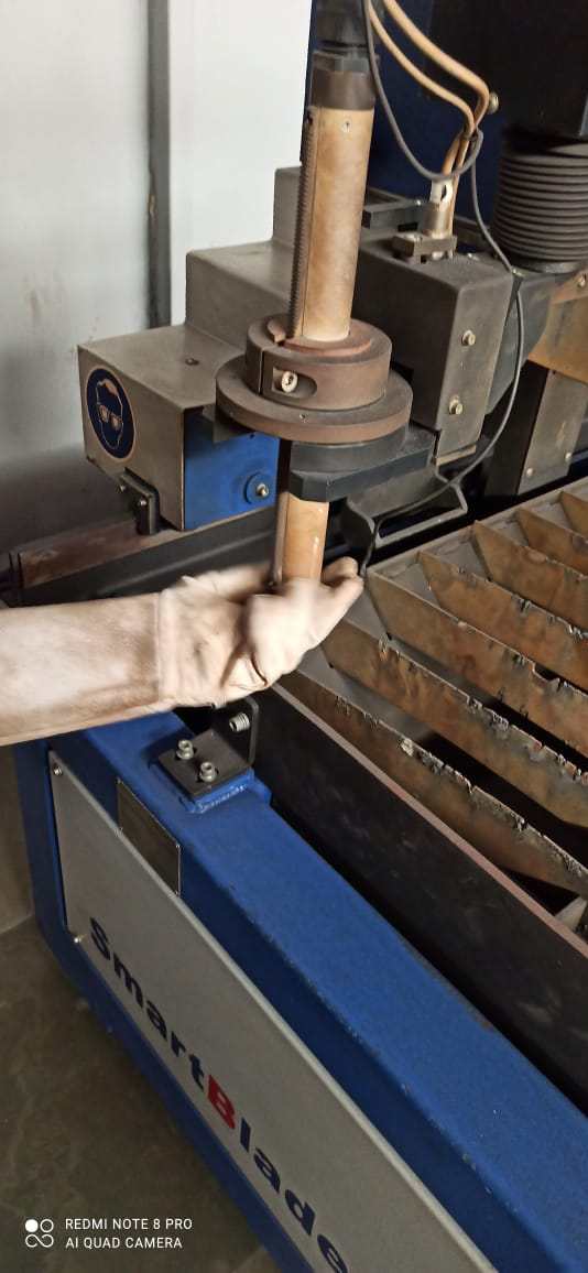
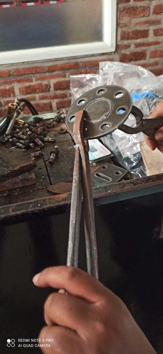
So using the glove's he removes the holdeon the plasma tip in which nozzle is housed
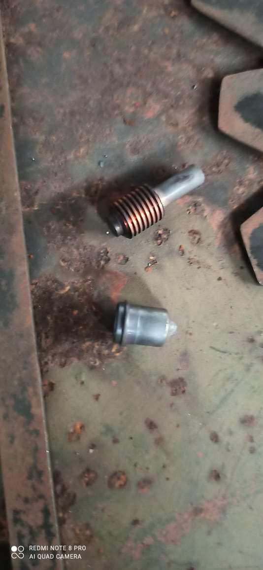
This is the image of the old nozzle
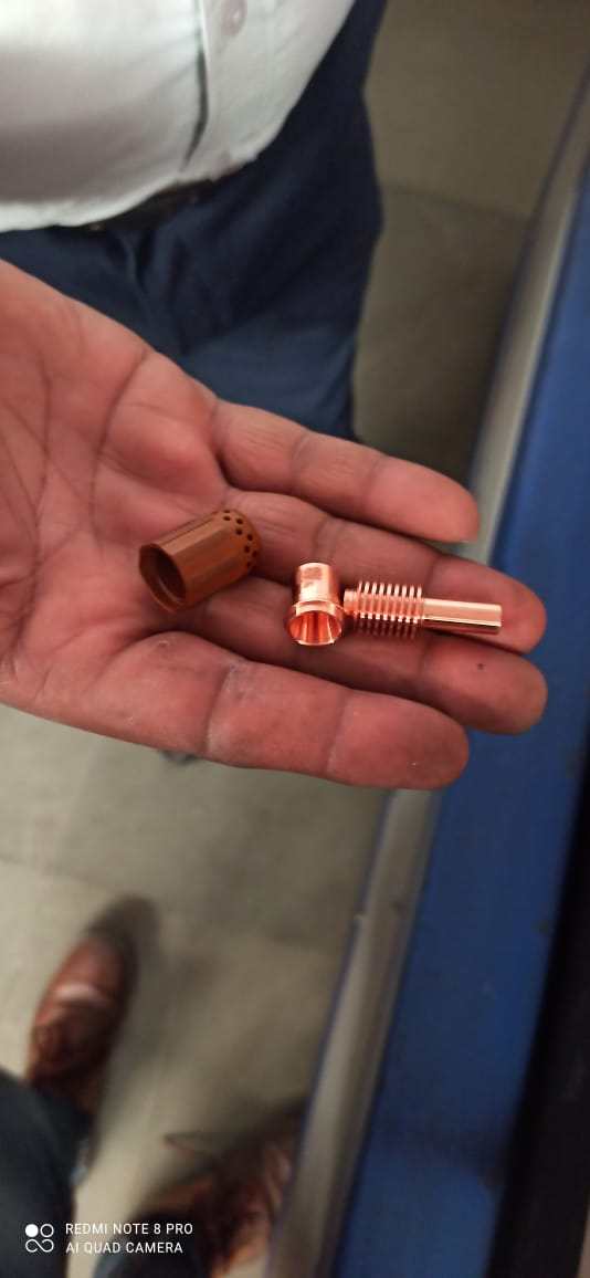
Look how shinny the new nozzle is this , he told us that it is made of some kind of tungstun-copper alloy
Then he gently close the nozzle housing after placing nozzle inside it
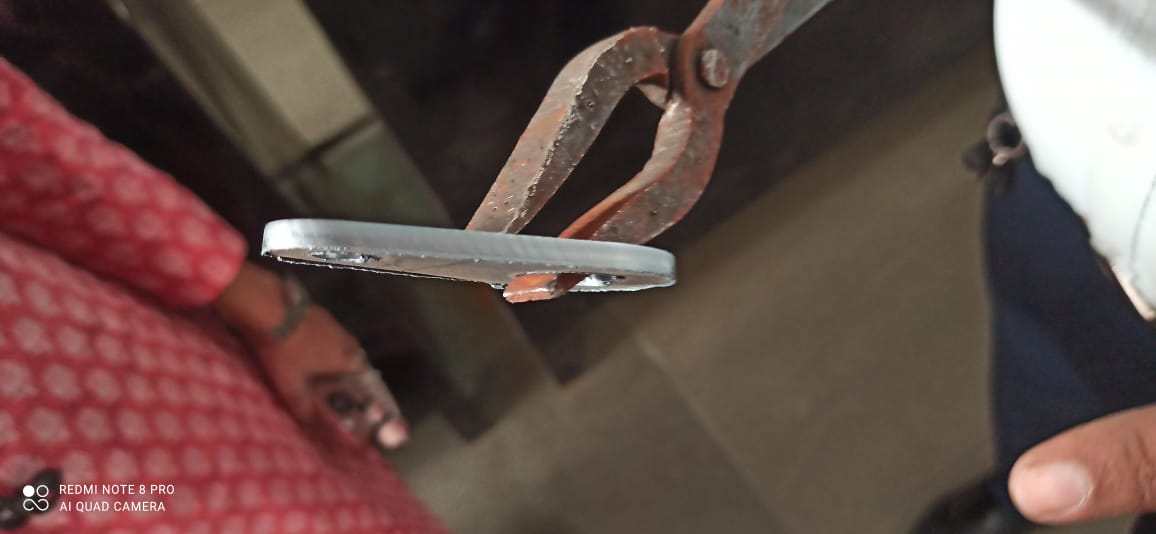
We cut again with replacing the nozzle , he results were impressive as compare to the last one , but one problem happens , there was some rust on some part dye to which laser was not able to cut the inner circle perfectly
We cut again and got best result
You can see no extra marks , no bur and the smoothness was awesome
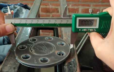
The demension were almost exact as the cirle was suppose to be 100mm and it came 100.6 due to a .2* taper given by machine
Group assignment
I require to design something by myself , so i designed a keychan as my keys were lying empty and we dont havehave much material left as by cutting several test we have utilized lot of material , as well as my team cut before me so they also used material , so my instructor me to make something small
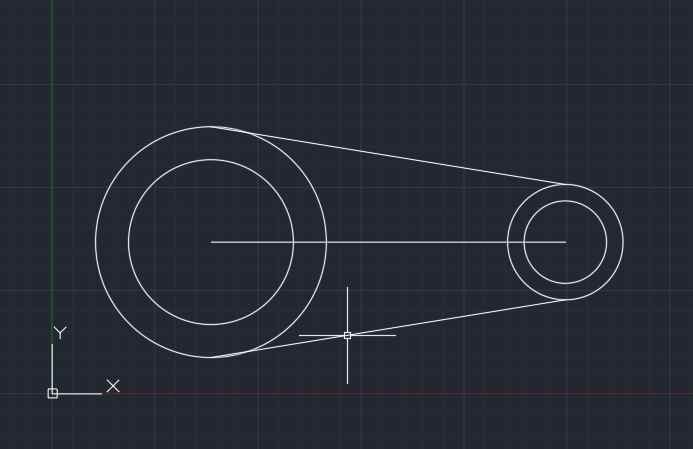
I used AUTOCAD TO design this key chain taking in mind the i shouldnt cut anything which is less hten 6mm in size as this machine has not good acuracy when cutting something less then 3 mm
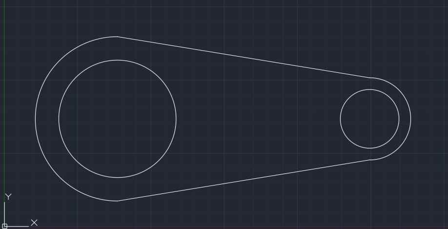
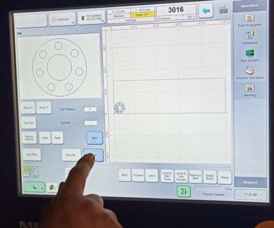
i Created DXF file and added the file to pendrive , for cutting
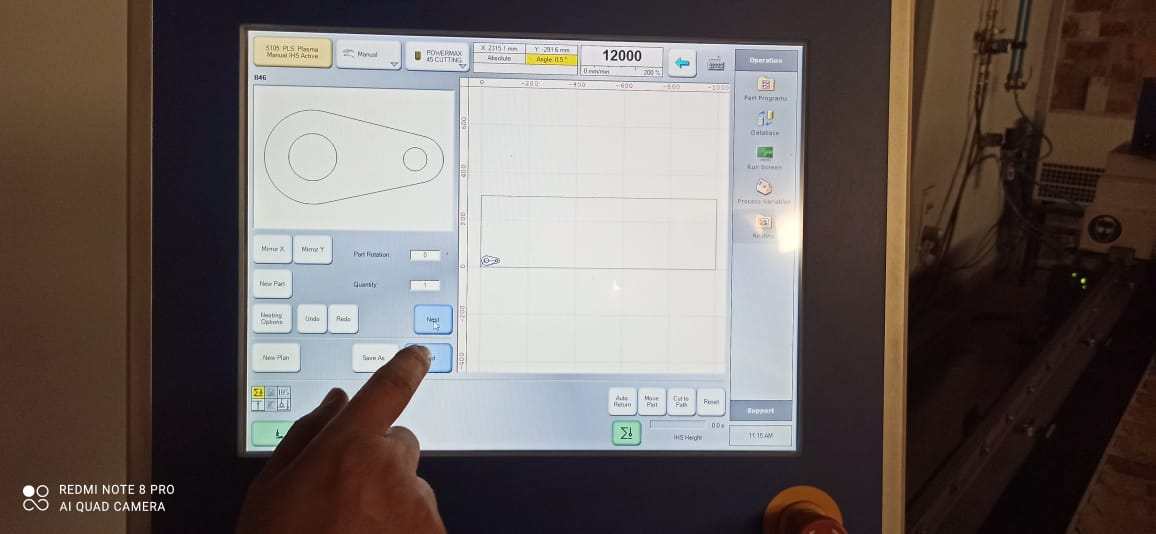
Added the file to the system
Machine generated the tool path
Plasma cutting my design
You can see sideways how smooth it is
I really like my new keychain and planned to polish this
If you want you can download the AUTOCAD editable file
key chainFAB FILTER MARK 1 by
PULKIT TALWAR is licensed under
CC BY-NC-SA 4.0
![]()
![]()
![]()
![]()