COMPUTER CONTROLLED MACHINING
The objective of this week is to make something big which has to be made on the wood router. I have to make a baby cradle for my Finalproject so i thought that i should make one in this week itself.
So this week we are going to work on a machine which can have a safety issue if we are not careful.
Our instructor Mr. Rahul Gautam briefed us about the safety and also the operation of the machine.
About the Machine
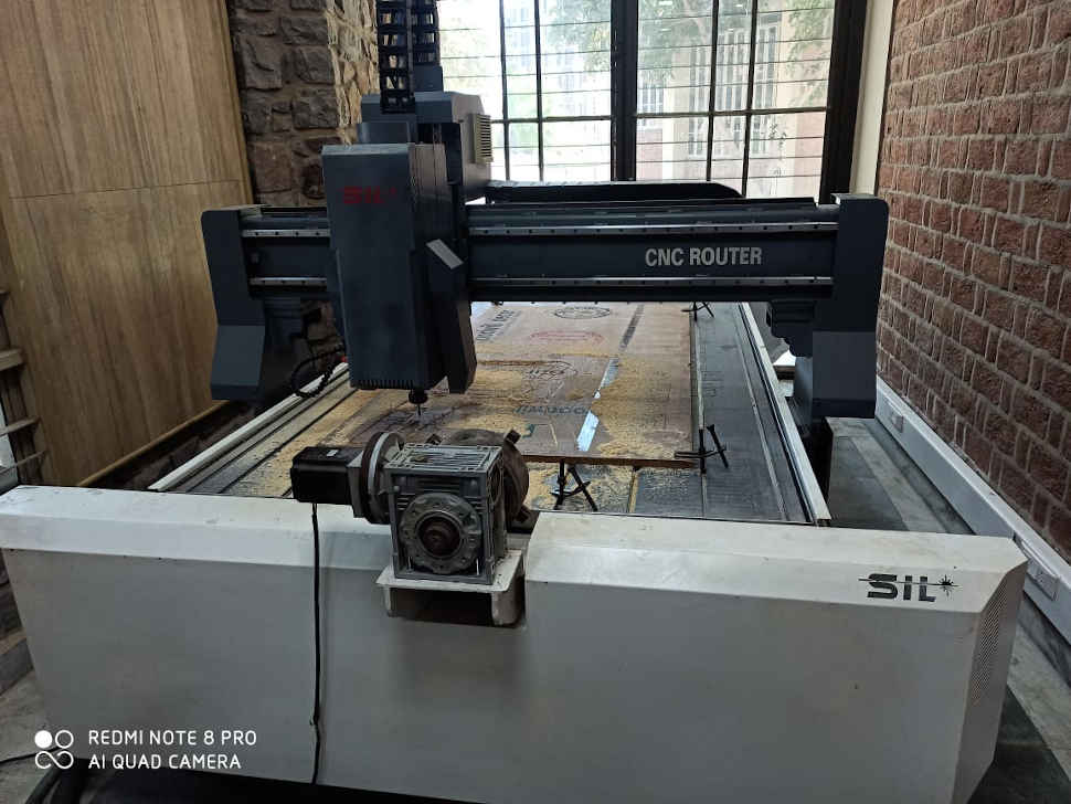
This was the SIL-1325 CNC Router that we had with a bed size of 8X4 feet.
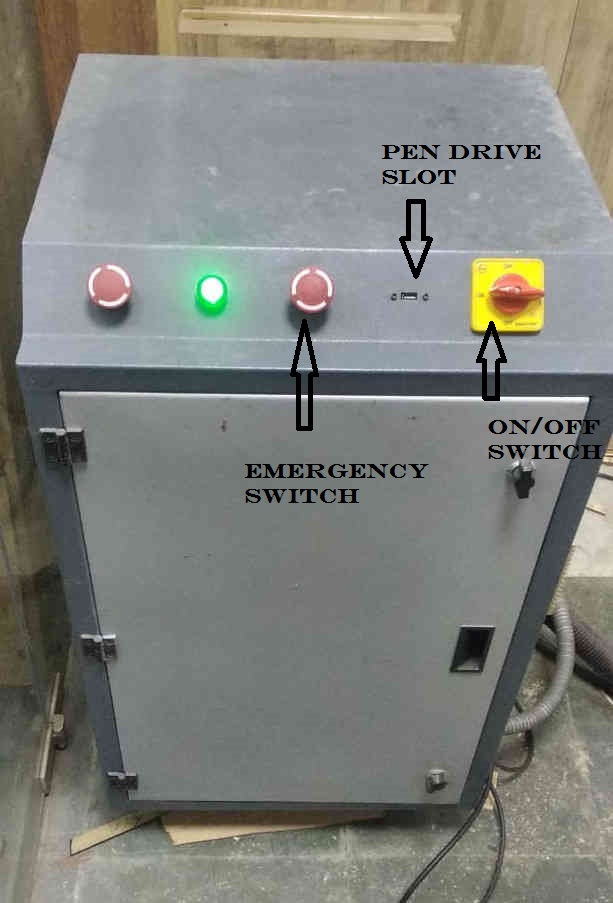
The front controls are shown here. The left most emergency switch is to turn the spindle off.
The rightmost switch is to turn the machine on. The middle emergency switch is to stop the machine
altogether and this is the one we need to press in case of emergency.

Setting the Machine
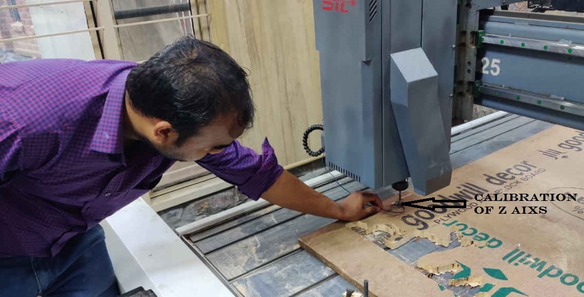
There are a number of buttons which are used to set the machine according to our requirement. It is important to bring the machine to home position and then the Z axis calibration. The machine starts to cut according to the file given to the machine.
Homing
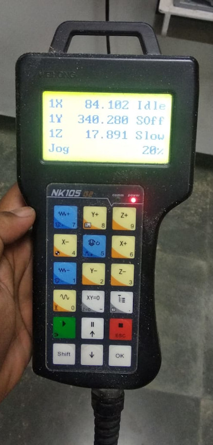
The teach pendant is used to bring the machine to home position. we need to press shift and 4 together for it. X+, X-, Y+, Y- buttons are used to move the machine to the different positions. There is a button for rapid manual speed which is just above the play button which is used to move the machine rapidly.
Setting The Origin
We can set the origin according to the placement of the material. The X and Y axis are set by pressing XY=0 and then the z axis is
set by prseeing shift and zero to surface the tool and then y=0 is pressed.
Group Assignment
There are a parameters like speed, feedrate which have to be controlled during machining. There are different types of tools which are involved to cut the pieces as well. So it is a good practice to know about their nomenclature.
Cutting speed is defined as the speed of the tool (usually denoted in feet/min) when it is cutting the workpiece. The cutting speed is mentioned in % on the teach pendant from 10% to 100%. The instructor suggested not to go beyond 50% for safety reasons.
Feed rate and spindle rpm are related. Feed rate is the distance travelled in one revolution of the spindle. The spindle speed is denoted by a number followed by S being the slowest and 4S being the fastest. The maximum spindle speed at 100% is 3200 rpm.
TEST ONE
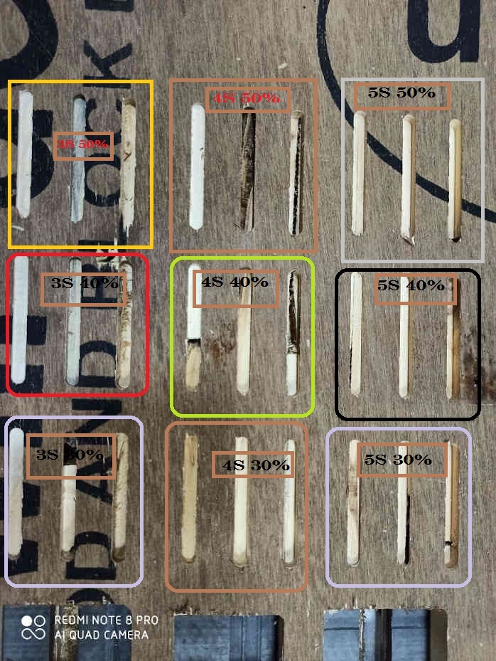
We cut the test parts at different feed rates and speeds by making the design on the ASPIRE software itself. The feedrates we used were 30 40 and 50 and the speeds we used were 3S 4S AND 5S. We found that the surface finish at 3S and 30 was good and the noise produced was also very low
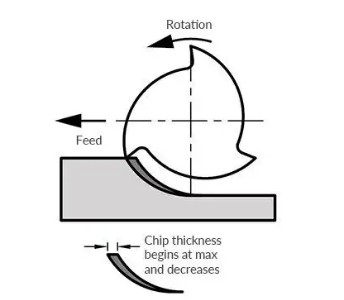
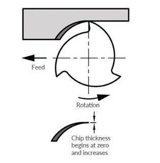
Climb and Conventional Milling
There are two distinct ways to cut materials when milling: Conventional Milling (Up) and Climb Milling (Down). The difference between these two techniques is the relationship of the rotation of the cutter to the direction of feed. In Conventional Milling, the cutter rotates against the direction of the feed. During Climb Milling, the cutter rotates with the feed.
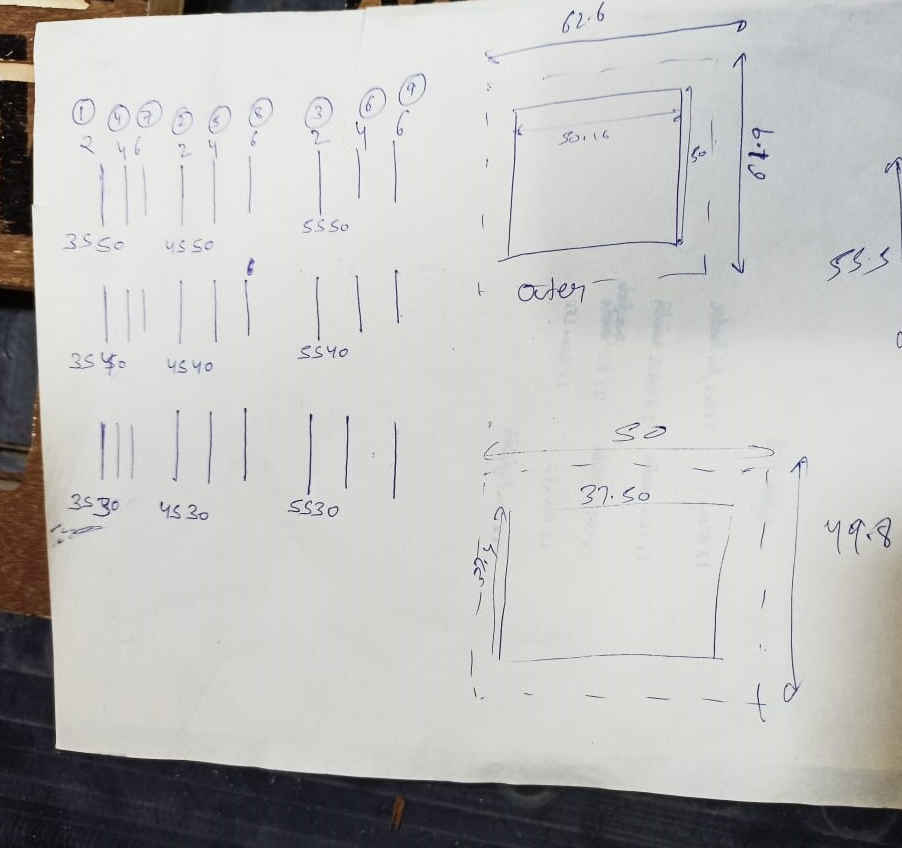
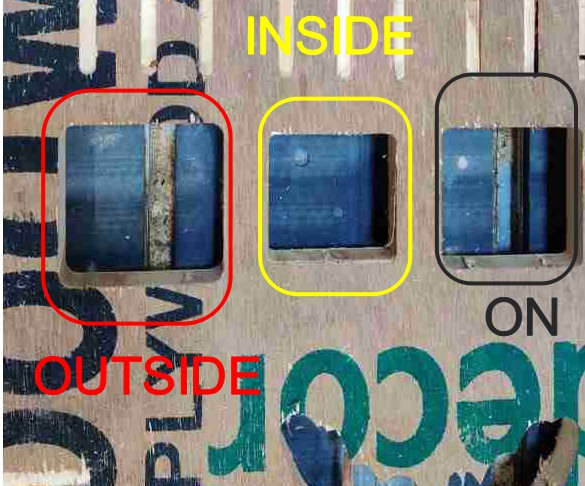
TEST TWO
We did the testing for OUT IN and ON the line of the drawing. The three rectangular pieces were cut with
OUT IN and ON the path approach.
The result we obtained for are :
(i) The Rectangle for IN path came out to be 50x50mm exact and the inner portion of rectangle was 37.4mmx37.5mm.
(ii) The Rectangle for OUT path which came out to be is 62.6mmx62mm and the inner rectangle is 50mmx50mm.
(iii) The rectangle for ON path came out to be 55.5mmx56mm and the rectangle came out to be 46mmx46mm.
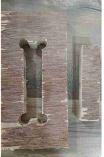
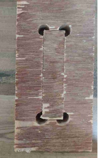
Test Three
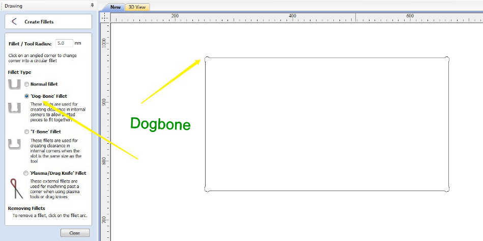
The wood we are using is 19mm thick so we wanted to test if it can go in a rectangular hole of 19mm with the dogbone feature.
So we tested it by cutting two different features (i) Rectangular hole of 19 mm width where the tool cut on inside the path (ii) Rectangular
piece of wood of 19 mm thickness .
I found that the piece was easily fit into the rectangular hole and this test gave me the confidence of
providing slots of 19mm width whereever a fit was required.
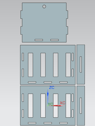
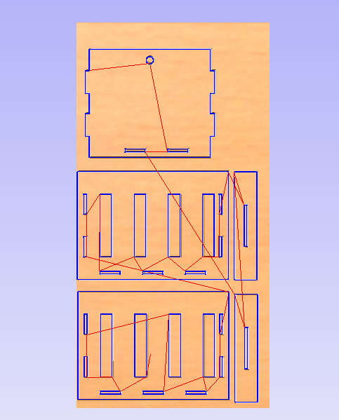
Cradle Design
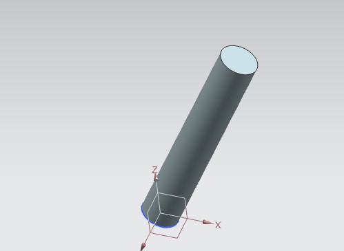
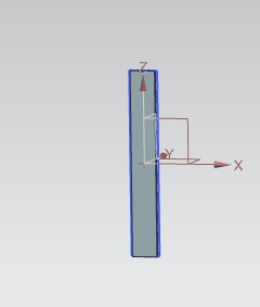
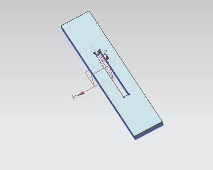
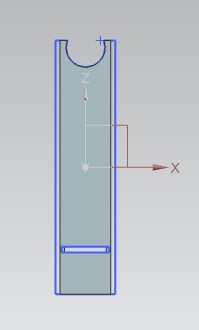
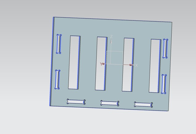
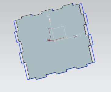
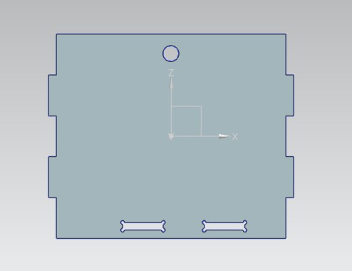
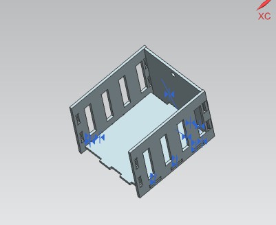
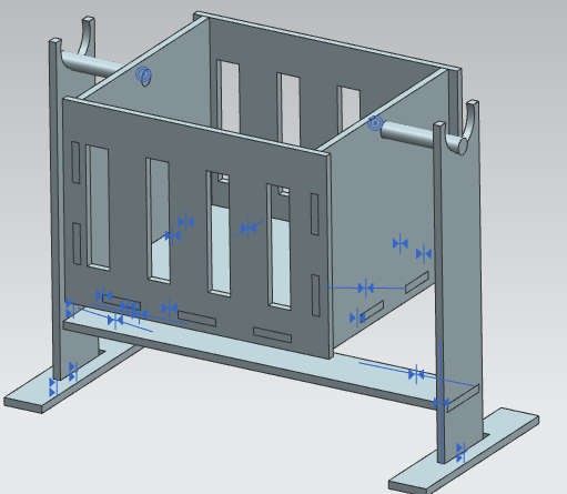
All the parts are drawn seprately using NX11 and then assembled to give a final shaoe to the cradle.
The design part requires correct knowledge of the fit which will be required to put all the parts in place
The thickness of the wood is 19mm so i need to provide a width of 19mm of the slots where fit is required. The
19mm slot came out through a test done to find out the tolerance.
Download NX file
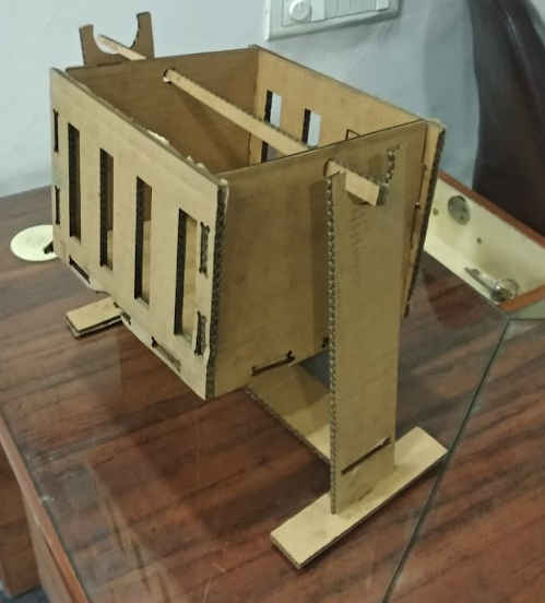
Testing on Laser Cutter
I wanted to test my part first on laser cutter. I took a card board and scaled down the size of the object and started cutting it on laser. The process for using the laser cutter and RD works software is expalined in week4
Steps
Step 1: Design Your File on any software if it is complex.
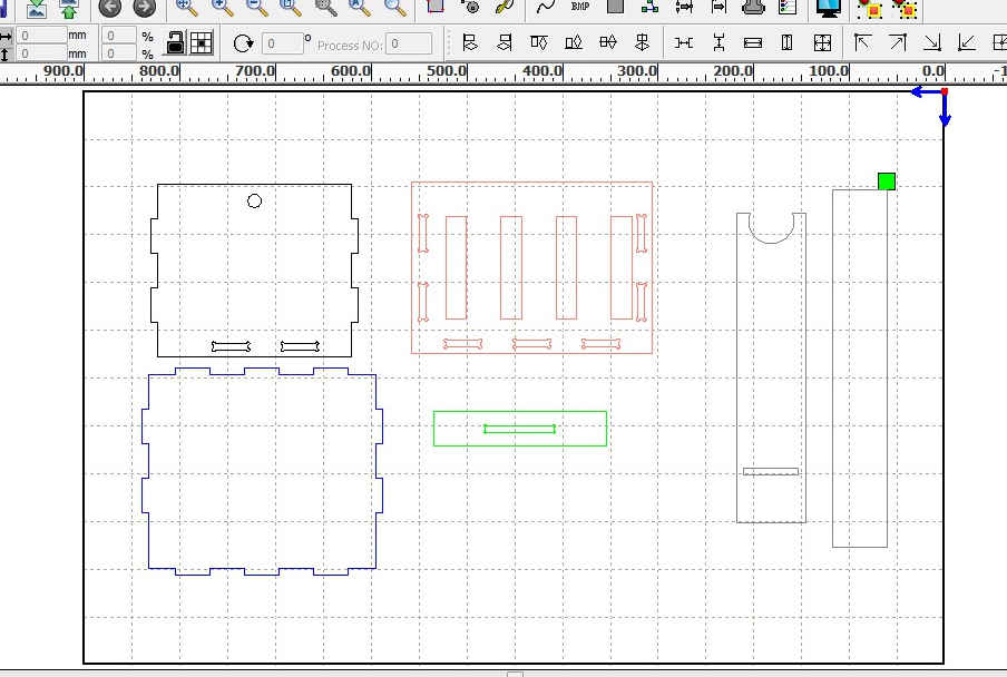
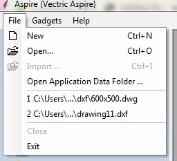
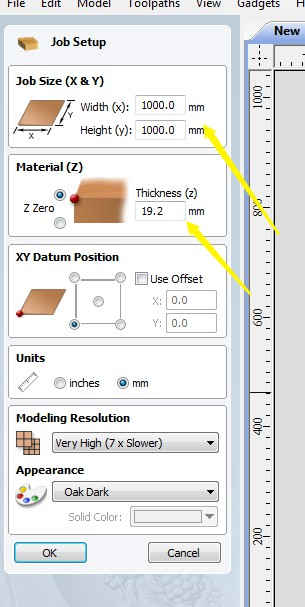
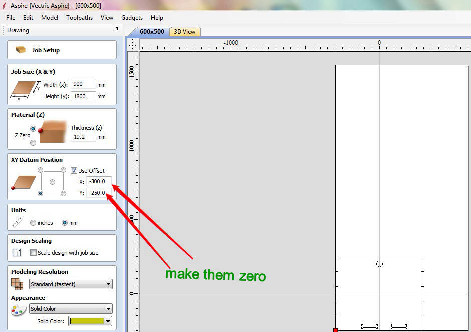
The drawing can also be drawm on Aspire if it is easy. You can download the Aspire from this Link. The web page will ask for the size of the sheet on which the drawing is needed to be cut. In our case it is 900mm X 1800mmand it is 19mm thick. i made my design using NX11 and exported my design as DXF. Then the DXF will be imported to the Aspire software.
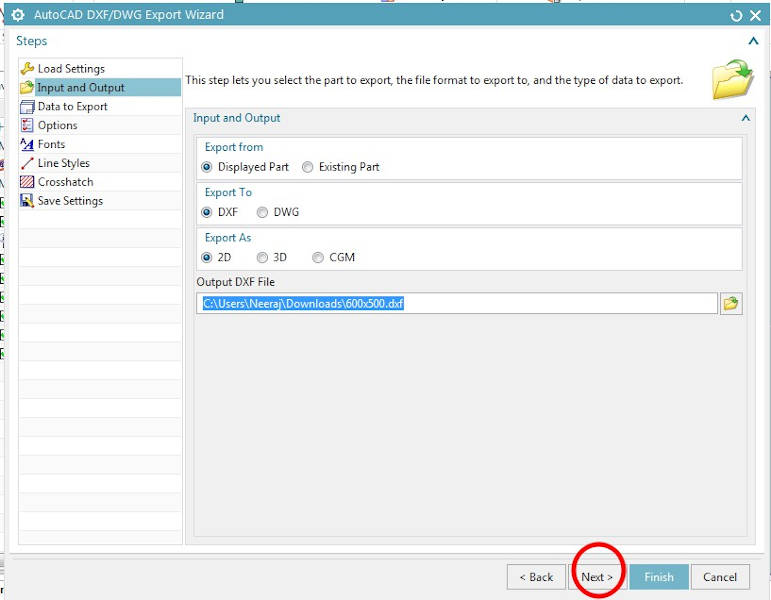
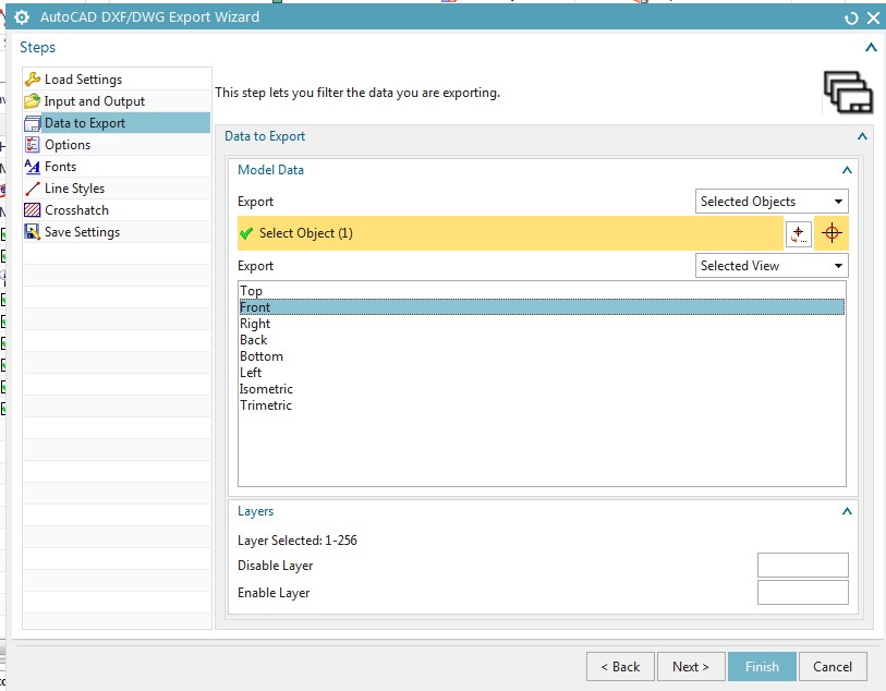
Step 2: Upload the design file in DXF format.
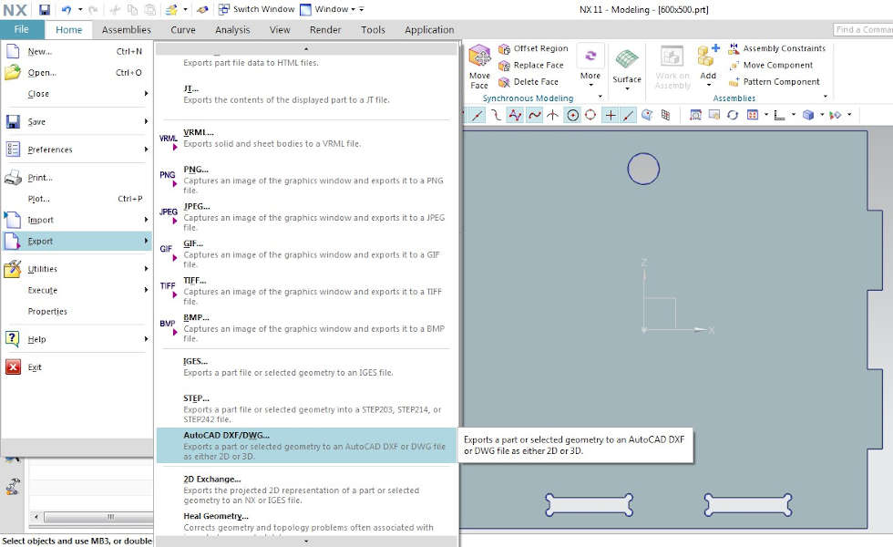
Converting into DXF format
The procedure of converting the design file into DXF is as following: Go to File>>Export>>AUTOCAD DXF
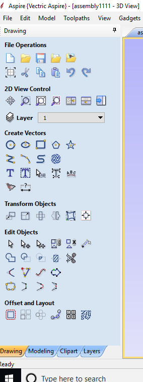
Upload the file and it will be visible on the interface. You need to join all the open vectors by clicking on the join tab. The duplicate vectors are deleted by right clicking on the drawing and selecting the duplicate vectors and deleting them. There is an option of DOGBONE in the toolbar itself which allows to give the corners a shape which will be easily fit.
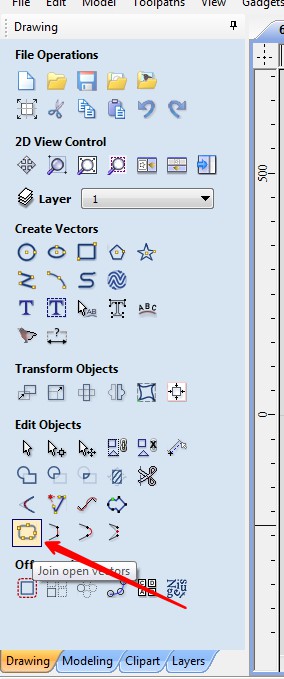
There is a problem of duplicate vectors and open vectors in the drawing. the duplicate vectore are deleted from the right click of the mouse and then selecting
select duplicate vectors>> delete duplicate vectors.
The open vectors are closed using the join option present in the toolbar.
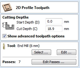
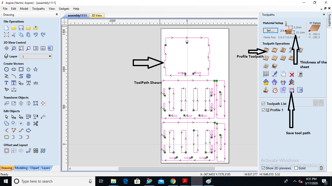
Step 3: Creating Toolpath
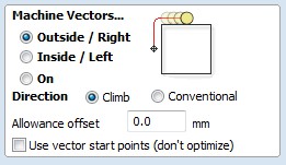
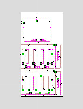
The toolpath is created according to the outside or inside features in the drawing. The internal features will be cut first by the machine followed by the external one. We can give the features the type of cutting it requires be it outside the line or inside the line and on the line.
Note: It is important to remember to delete all the duplicate vectors.
Step 4: Saving the Toolpath file
The toolpath is saved as the CNC file format . Clicking on the save toolpath button asks for the format in which you want to save the file.
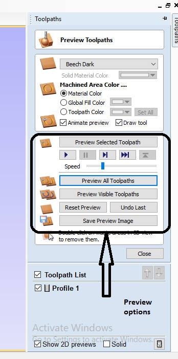
Step 5:Export the file to the machine
The file needs to be exported to the machine and the file is shown on the teach pendant. Before you start cutting on the machine it is required to set the origin an all the axis and then start the cutting process.
Cradle
It took me almost 8 hours to cut all the parts of the cradle. It is very important to clamp the material tightly and operate the machine on 20 feed and 3S speed. Becuase the clamp can come out and the part can be misaligned. and it is also iportant that you design your part very carefully if there is a mismatch of even a cm can ruin all the model.
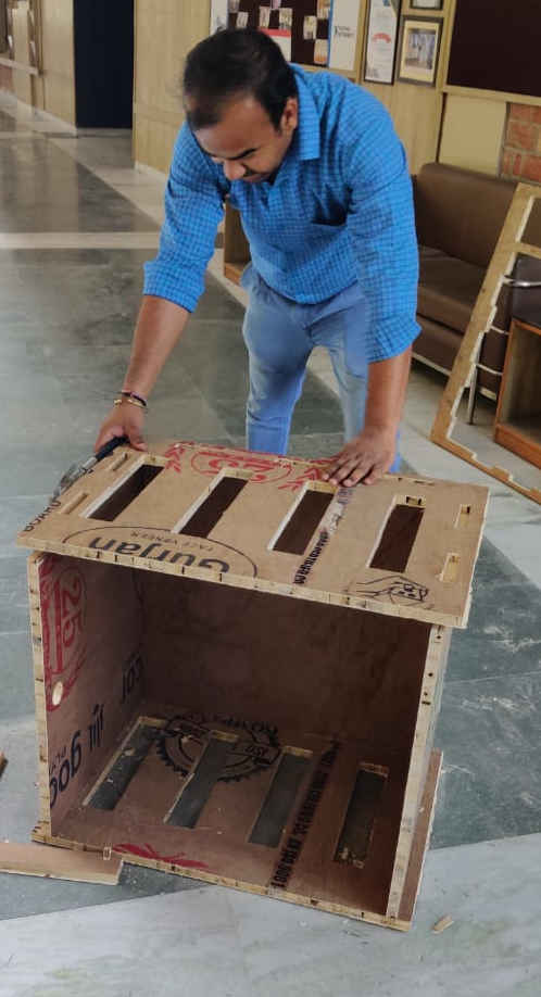
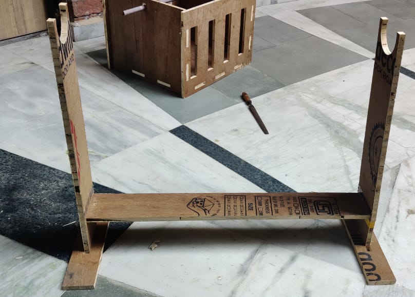
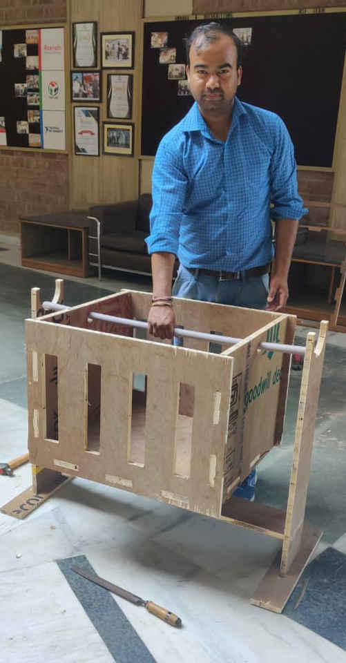
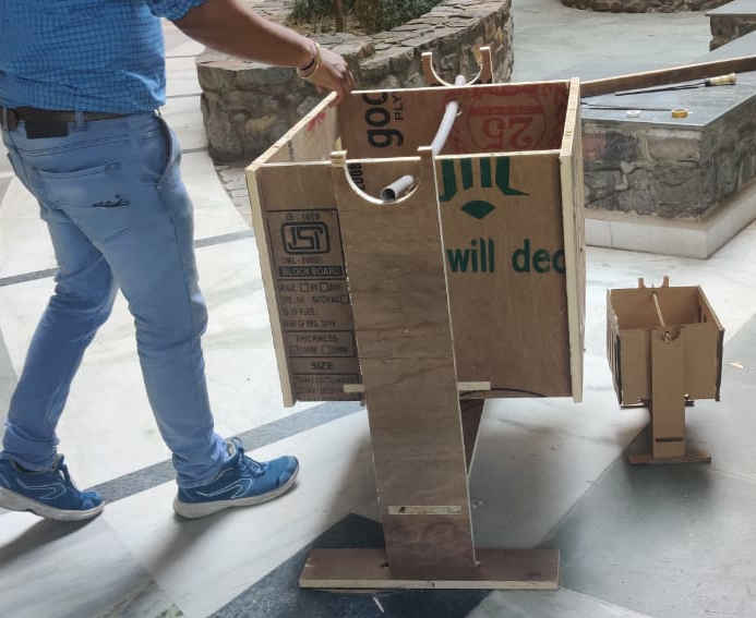
HERO SHOT OF THE CRADLE
Problems Faced and Conclusion
The machining of cradle was the toughest work since you need to be with the machine all the time.
You cannot leave the machine even for a second. The reason behind is that when a small piece is cut from the log of wood, it sticks there or can come partially out
which can cause restriction in the motion of the tool which results in tool damage and uplifting of the log which can really be very dangerous.
It happened to me 2 times but since i was there i could press the stop button and then resume the cutting after removing the cut part.
one more important point is the clamp which needed to be fixed tightly on the bed from various points. If the wood is not tightly pressed with clamp then
then the wood can come out and i swear it will take a hell lot of time to adjust it to its original position. It happened with me and it took me more than 2 hours to settle it again.
The test performed before as the group assignment is very important because from that portion only you will be able to design the slots needed for fit.
According to the test performed, i decided to do the cutting with the 30 feed and 3S speed but while cutting with these settings, i found that the wood was coming out of its position which was very dangerous. So i had to work with the reduces feed rate of 10 and 20 (10 mostly) which increased the time of cuttng to around 8 hours. The clamps of the machines are now old and they need to be replaced as they are not able to hold the wood at higher feed rates.
The another reason for taking 8 hours to machine was that its thickess was 19mm and it had a lot of cutting sections which eventually increased the time. But i did not machine it in one go but distributed the machinng to two days.
As the cradle which came out was very robust and it was very heavy at the same time and one leg of the cradle also broke down after. The cradle's leg was broken and it was a design fault from my side as i did not leave enough material to the sides of the press fit feature which can take the load of the cradle. So i had to move to another design for the cradle. The another reason for moving to another design was that i wanted to add some new features for the final project cradle. The new design of the cradle is completely different from this one. You can see full documentation of the new cradle on this page.