3D PRINTING AND SCANNING
This week we are going to make our designs in physical form and scan the materials around us using Scanners.The group assignment for this week is to test the design rules for your 3D printers. The individual assignment is to design and 3D print an object that could not be made subtractively and 3D scan an object.
3D PRINTING
3D printing or additive manufacturing is a process of making three-dimensional solid objects from a digital file. The creation of a 3D printed object is achieved using additive processes. In an additive process an object is created by laying down successive layers of material until the object is created. Each of these layers can be seen as a thinly sliced horizontal cross-section of the eventual object. 3D printing is the opposite of subtractive manufacturing which is cutting out / hollowing out a piece of metal or plastic with for instance a milling machine. Source:3dpriting.com
Our FABLAB is having Makerbot and ULtimaker 3D Printers.
MakerBot Industries, LLC is an American desktop 3D printer manufacturer company headquartered in New York City. It was founded in January 2009 by Bre Pettis, Adam Mayer, and Zach "Hoeken" Smith to build on the early progress of the RepRap Project. It was acquired by Stratasys in June 2013.Ultimaker is a 3D printer-manufacturing company based in the Netherlands, with offices and assembly line in the US.They make FFF 3D printers, develop 3D printing software, and sell branded 3D printing materials. Their product line includes the Ultimaker S5, Ultimaker 3 series, Ultimaker 2+ series and Ultimaker Original+. These products are used by industries such as automotive, architecture, healthcare, education, and small scale manufacturing. Source:wikipedia
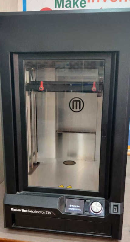
Our Fablab has MakerBot Replicator Z18 3D Printer. It has 12 x 12 x 18" Build Volume,
100-Micron Layer Resolution and it uses Uses PLA & MakerBot Tough PLA Filament. It supports MakerBot (.makerbot) file.
The build volume of
Ultimkaer is 230 x 225 x 205 mm, desktop space is338 x 358 x 389 mm and Layer Resolution: up to 20 micron (0.02mm)
and Materials: ABS,PLA,PET.
Safety and Precautions
Always unplug the printer before doing maintenance or modifications.
This equipment can radiate unintentional radio frequency energy
and, if not installed and used in accordance with the instruction manual, may cause interference to radio communications.
Always let the printer cool down for at least 30 minutes before doing maintenance or modifications.
Only use your printer in a well-ventilated area.
Technologies of 3D Printing
There are various 3D printing technologies available. These are 1. Strereolithography 2. Digital Light Processing 3.Fused Deposition Modeling (FDM) 4. Selective Laser Sintering (SLS) 5. Selective Laser Melting (SLM) 6. Electronic Beam Melting (EBM) 7. Laminated Object Manufacturing (LOM). All the technologies are used in various types of 3D printers. This page helped me to learn about these technologies.
DESIGN RULES ON MAKERBOT
Before start printing objects we need to find the characteristic of the machines which we are going to use. There are many tests which are performed to find out the design rules of the machine.
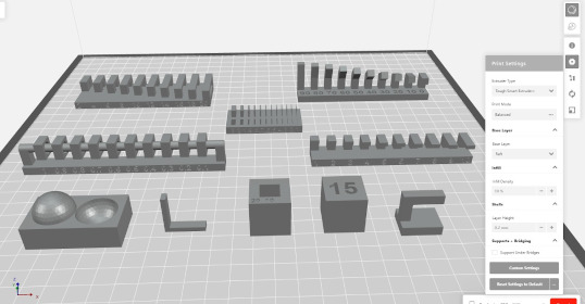
In group assignment we decide to print the STL files from Fab Academy.For this we used Makerbot Replicator Z-18 3D Printer.
The settings are:
1. All the parts are printed without any support.
2.Infill:10%
3.Layer Height:0.2mm
4.Raft :On
5.Material Used:Tough PLA(Slate Grey)
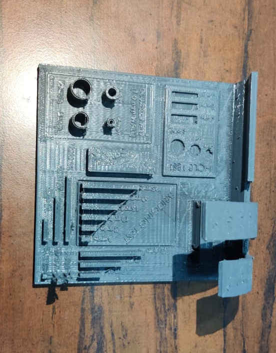
These are the test pieces that were carried and taken to characterize the 3d printing machine.
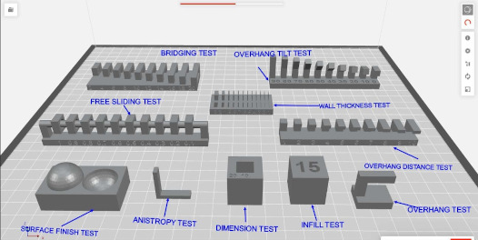
1.Bridge Test
This test is used to find out the length upto which the brdge can be laid down between two supports. It means how it easily it can print without any support upto certain length.
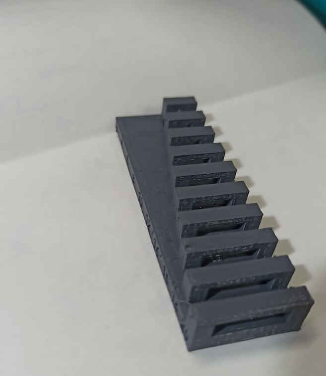
The test showed that the print was complete and clean upto 30 mm length.
we have also printed a test kit signifying all the test involved,. Makerbot was used to print these tests to find out the capability of the machine.
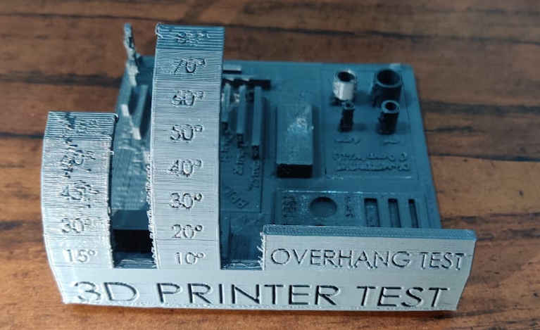
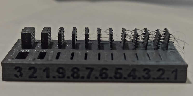
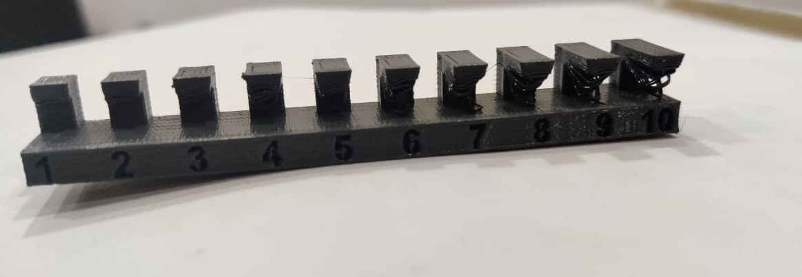
2. Overhang Tilt Test
A 3D printing overhang is any part of a print that extends outward, beyond the previous layer, without any direct support.
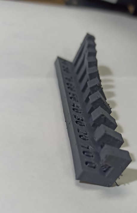
In this test we found that the overhang was complete and clean till 20 degrees and after that strings started to come which means that it reqires support to print above that angle.
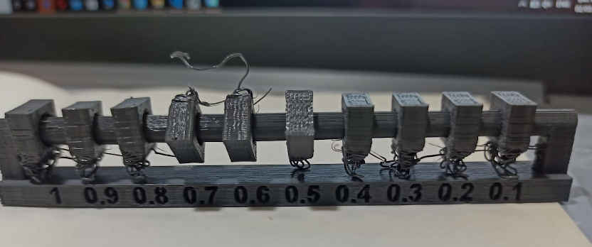
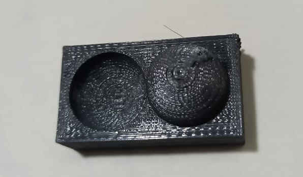
3. Freesliding Test or Clearence test
This test is performed to find the clearence between two mating parts. In this test the clearence between a common
rod and holes are varied to find out at what clearence does the relative motion stop. We found that the clearence
at which the movement is smooth is .5mm and after that the motion stops. It is due to the shrinkage of the material. The test is
performed with PLA material on Makerbot machine.
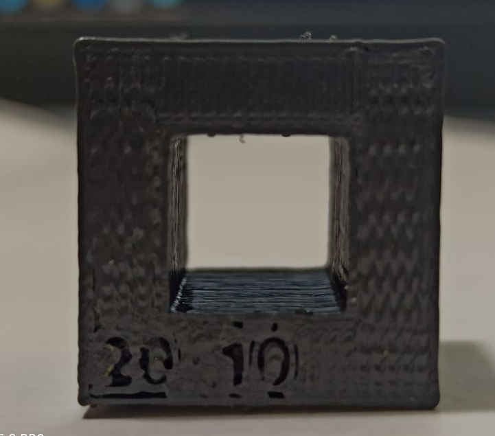
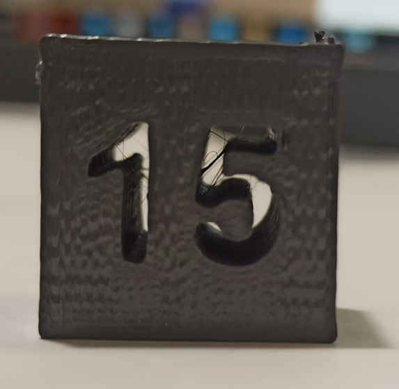
4. Dimension Test
Dimesion test is used to find the accuracy of dimensions. The printed object after shrinking chnages its dimension. so we need to have info about how much it is going out from the intended dimension. In our case the internal cavity redubes to 9.8mm and the outer cavity came out to be 19.74mm.
5. Wall Thickness and hole Test
This test is performed to find the minimum wall thickness and minimum dimension of hole that can be printed from the machine. We found that the printer was able to build the wall till .4mm without string and .1mm minimum with strings over it. The holes were through till .4 mm and after that the holes could not be completed.
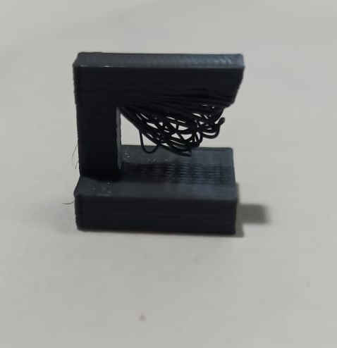
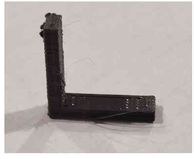
6. Overhang test
This test is performed to find out the limit of the machine as to how much length printer can make a overhang part. The test piece started to getting distorted just after 5 mm of the overhang. there were strings of the material which were coming out after 5mm.
7.Anisotropy Test
The material property of the test part is going to be different in digfferent directions. it will be higher where
the strans of the material are longitudnal and lesser where they are transverse.
8.Surface finish test
The surface finish in the test piece is a function of the angle and overhang. In the test piece, where the angle is greater the finsh is good but as the angle of the depositon is decreasing the surafce finish is getting rough.
9. Infill Test
The strength and the density of the test piece will be higher and larger if the infill is higher and it will be lower if the infill is lesser.
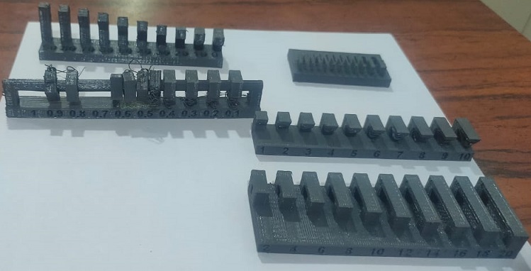
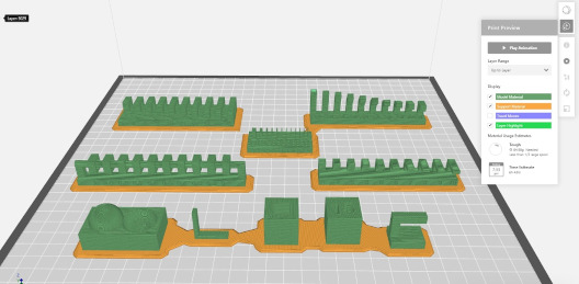
In some of the images it seems that first layer is warped but it is not so. The above picture shows the test prints put together. The base of all the test prints are flat as the quality of the printer and the material is good.
The design files were downloaded from the class schedule page
Working on Ultimaker
The ultimaker machine was not printing the material. we found out that the spool which i was using was kept in
the machine from many months and the material was not able to melt inside the nozzle. We changed the spool and found out that the
material start melting and it was coming out easily on to the bed. But then it was not sticking to the bed properly, we decided to
change the adhesive but there was no improvement. We decided to calibrate the bed using a piece of paper. You can use this
video to
know how to calibrate the bed. After bed calibration, the printer started to print properly.
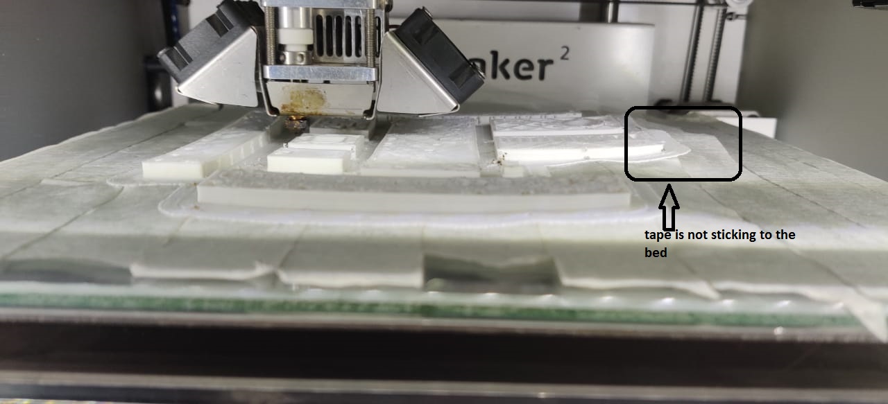
But after some layers of printing, the base statred to come up. We were getting this issue earlier as well. we had tried using some adhesives also but i did not work.
so we decided that we must use a masking tape as the material can stick to it since the surface of the glass was very smooth and the material was not stcking to it. So i decided to go with the
tape but i did not work there as well and the print could not be completed.
I contacted the service provider for this problem and he explained that the ABS material should be printed in a closed chamber. If i want to print PLA then open environment will be suitable but for printing ABS a closed chamber is required.
So while printing ABS with applying adhesives as well, i did not get the required output. Our lab does not have PLA for ultimaker as the diameter for the ultimaker material 2.85mm
so we cannot use the material of makerbot od stratysys in it. We are now developing a box for the ultimaker machine so to give it a closed chamber and then we will see if we can a good print with ABS.
3D Printing
The individual assignment is to design something which cannot be made from the 2.5D machining techniques.
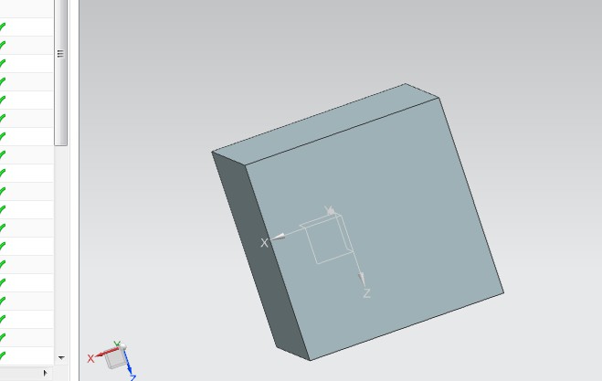
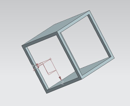
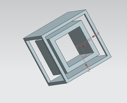
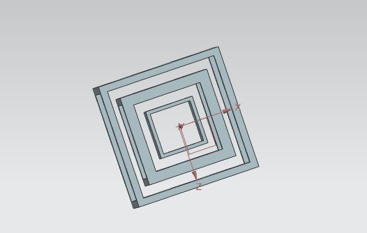
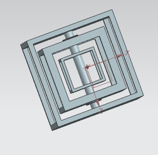
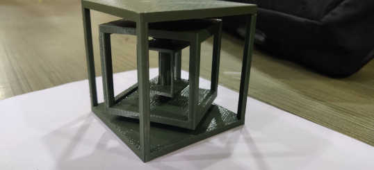
I designed a cubical shape toy with relative motion of the inner hollow cubes. I have chosen this shape because
it is difficult to make it through 2.5 d and if it is made through a subtractive process then the loss of material will be very large.
The print was done makerbot using software makerbot print. The settings used were .2mm layer thickness and 10 % infill. But the quality which came out
was relatively poor.
I was watching 3D priting of the shape and i realised that it is also priting the support and the support
in maker bot is of the same material which would have been very difficult to remove.
the support was very essential since my part was having a lot of overhanging parts. The support which was
there to print would have been very difficult to remove.
I had to take a decision and i moved to
stratysys. Stratysys is a 3d printer with best quality
3d printing quality. Stratysys is having a seprate material for the support and that support material is very
easy to remove as there is a solution in which the whole shape is dipped and the support material gets
dissolved in the solution itself. The quality which comes out is best and they are used in industrial grade
applications.
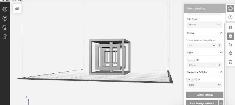
Step1: Make the design on CAD software. I have used NX11 to make my own design.
I have
Step2: Export the design file to STL format .
Step3: Open the file in Makerbot print
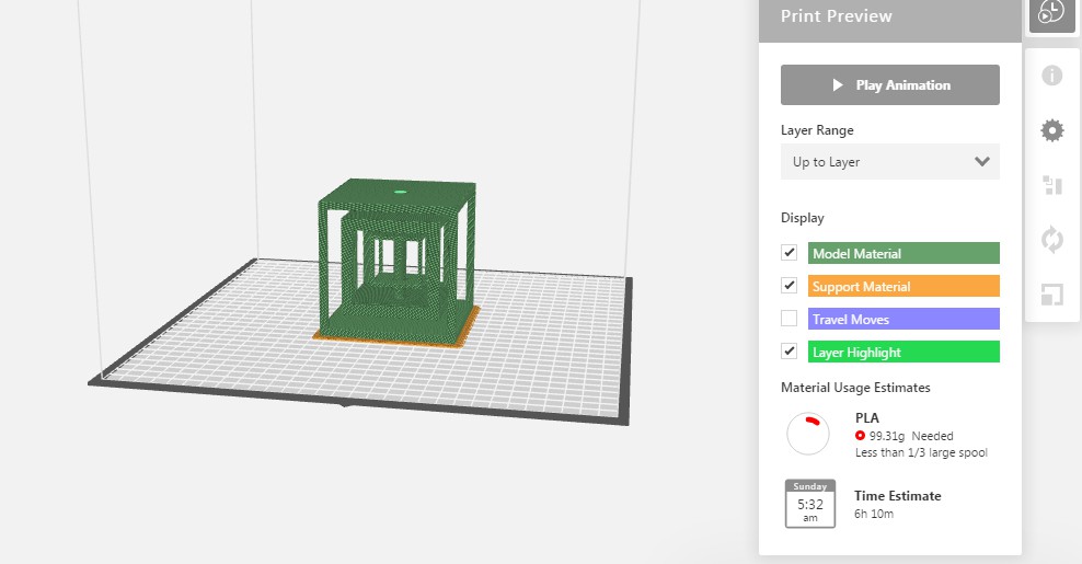
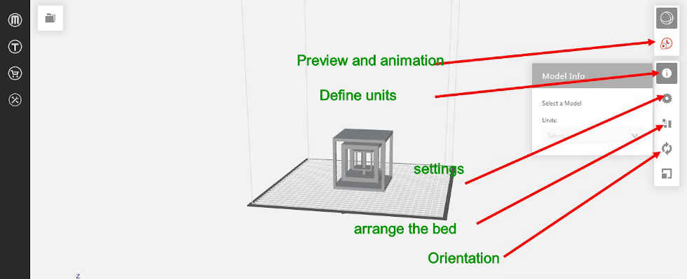
Step4: Change the settings as required. in my case the settings are changed to no raft,.2mm layer thickness, 10% infill density, temperature 215 degrees shell (recommended)and material used is PLA.
Then i moved to the next printer to print and printed the toy. The layer thickness is .2mm and the infill density is 10%. the material used is ABS. Here the software which i used is Cradcad. The interface of all the 3d printing softwares are almost the same.
Download all Design NX and STL file
The video link is this
Why the part cannot be made using conventional technique
My design is having three hollow cubes which are having relative motion to each other. This design cannot be made through conventional technique because it requires relative motion among all the cubes and the tool will not be able to cut the pieces for the inner section of the designed part.
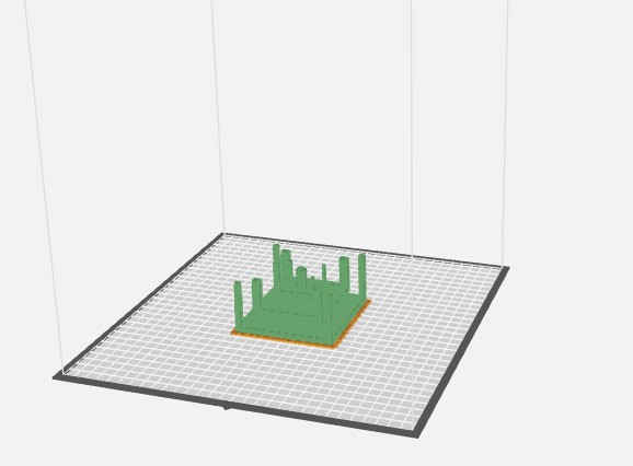
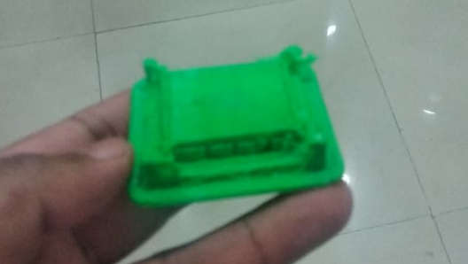
Failed part
The first attempt to make the design failed because it was having a lot of overhang parts and because of which
a lot of support material got inside of all those overhang parts which would have been difficult to remove as the support material
was also of the same material. the removal of the support from that small
dimension was not possible. so i had to stop in between and then i used STRATYSYS F370 to make the print as
the support material in this case is easily removed .
Advantages and Disadvantages of 3D Printing
3D priting is best for prototyping and small batch manufacturing but not a viable option for mass production as the time taken to print can vary from
hours to days.
3D pritning technology can make any complex shapes whcih cannot be made from traditional manufacturing technologies.
The material used for printing like in FDM requires thermoplastics to melt which pollutes the working environment
so it is essential to keep ventilation in the working area.
Scanning
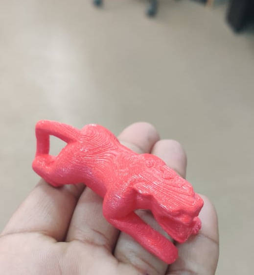
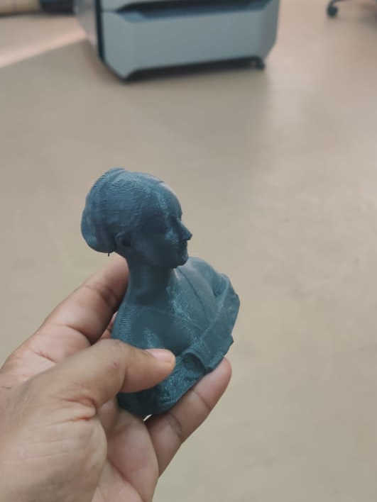
Qlone
It is a mobile app which lets you scan sitting anywhere and any object. You just need to have a sheet of paper having black and white squares which lets you scan the object. Since we were having A4 sheet with us so the scan we did is of a small object. The square sheet can be downloaded from the google link The qlone mat is essential to scan any object. you need to put the sheet on a plane surface and then put an object which you need to scan . One thing which should be kept in mind is that the size of the object should not be more than the size of the qlone mat because then it becomes very difficult to scan it.
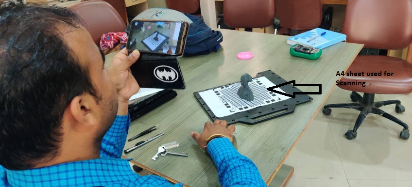
The app when opens and scans an object shows an dome like structure which is removed automatically when you scan the part in the back of the dome. The dome shape changes its color to transparent when the part of the object gets scanned. It is important to complete all colored pieces of dome to transparent dome anf then only the scan will be completed. I tried and scanned two shapes available in our fablab and they are scanned using Qlone itself. The app informs you when the scan is done. The file can be exported in various format as STL,OBJ and it cab send to other social media sites as well.
WORKING WITH X BOX KINECT 360
Now we have started to scan some items. We have KINECT XBox 360 with us.
For scanning, we used xbox kinect 360, The Kinect sensor is a horizontal bar connected
to a small base with a motorized pivot and is designed to be positioned lengthwise above or below the
video display. The device has an "RGB camera, depth sensor and multi-array microphone running
proprietary software", which provide full-body 3D motion capture, facial recognition and voice recognition capabilities.
It has a software available named as Skanect which can be downloaded from this link
Download Skanect
This is the video which i used for working with skanect on windows 7. I had downloaded the skanect software as gievn in the tutorial but the scannner was not able to open up. The scanner had a blinking point and it was never blinking when i was using skanect as the software for kinect.
I then searched for more options and i found other tutuorials explaining other softwares for using kinect x box 360.
The operation of using kinect can be learned from this Video
Since Skanect was not compatble with my laptop perhaps being Windows7 so we decided to downoad it in AFSHA's laptop and it was installed in her laptop succesfuklly but the kinect camera was not taking pictures with SKANECT. We tried several times with Skanect but were not able to take pictures with it. Because it was not able to access the camera of Kinect.
I am using windows 7 and because of which i am not able to work with kinect 360 so i am taking
help from Afsha to do this assignment.
There are a lot of softwares which has to be downloaded. I downlaaded 3D scan 3D preview and kinect runtime
in windows 7 but it did not work.
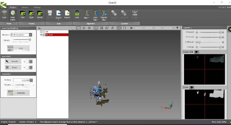
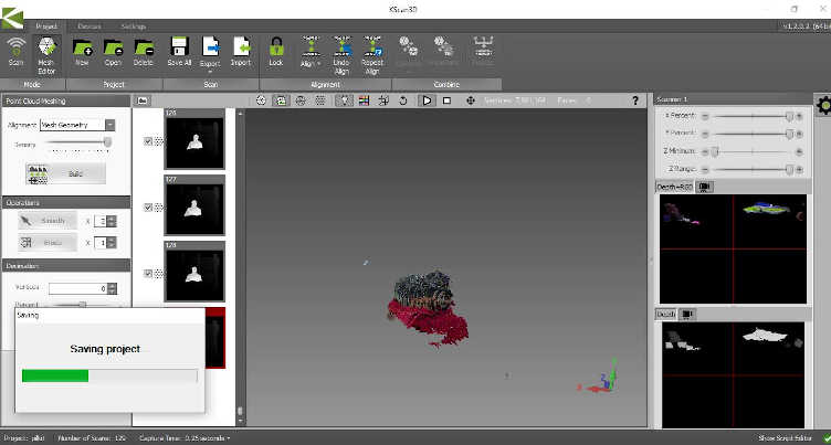
The system with windows 10 could read the input given by the Kinect. There was some problem with the kinect
because of which we could not get a
combined view of the images clicked.
We changed and increased the number of images clicked by us so that we can have a clear scanned
picture but there was issue aligning and combining the images.
Sometimes we came close to get nearly perfect scans but there were always some issues with the top
portion and the front portion.
The reason for our failure was that we did not get placed the scanner at a place where it can capture all the parts of the object because whenever we changed the position of the scanner there were some positive impact on some portion and negative impact on the other portion. The scanner was not able to combine all the images and which led to us to decide not to go with this scanner.
We have one more scanner from Zeiss but due to corona virus issues that facility is closed and we will experiment with that scanner also once the situation is normal again. we are accesing the facility but the college is closed.
New Laptop
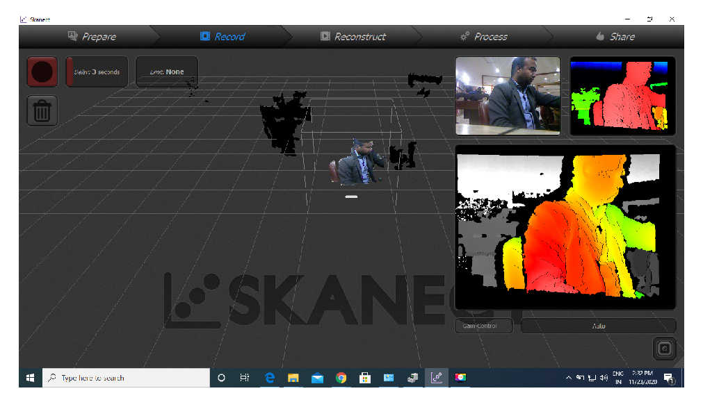
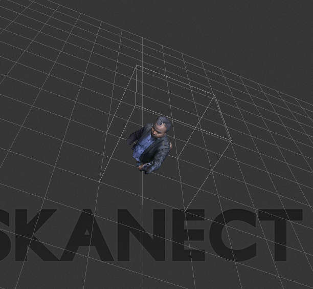
I have bought a new laptop with windows 10 on it. So by the advice of Mr.Salman (my global evaluator) i am again doing the scanning part. So i have easily installed the skanect software using this link and i have also downloaded and installed KINECT SDK. I have used this video to install and run the kinect scanner. This time all the softwares were installed properly and i could scan myself sitting on the chair. and if i campre this scanning with the previous ones which i did using Kscan 3d, i can see that the quality of the scan was good.
I have also converted the scan file into STL format which can also be used to 3d print the scan but the quality of scan in the free version of skanect is minimal and will be the best if i use the paid version of it. But right now i am using the free version of it.
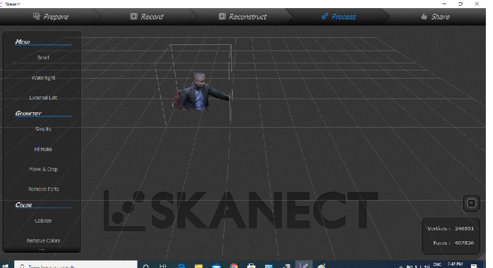


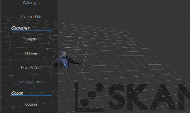
The skanect has some good features like water tight which actually closes the holes present in the scanning whch was not there in the Kscan3d because of which i could not get the required results.
Download STL FILE by SkanectI have exported the file as stl file whcih can be used for 3d printing.
I made two attempts for scanninf my body so both the STL files are present in the downloadable link.
Conclusion
This week was very exciting. we printed a lot of things on all machines availabile with us. Ultimaker, makerbot, Lilliput, fabx are some of the printers availaible at our faciltity. i also used Skannect and Qlone for the scanning part. i found that the qlone is very much portable and u can scan anything anywhere.Kinect has its own features which make the user scan larger onjects also. You cannot scan any tranparent objects with the scanners.