COMPUTER CONTROLLED CUTTING
So we are going to work on machines this week. We have been given group assignments and individual assignments also. The group Assignment is to characterize your lasercutter's focus, power, speed, rate, kerf, and joint clearance. The individual assignment is to cut something on the vinylcutter design, lasercut, and document a parametric construction kit,accounting for the lasercutter kerf.The machine availaible with us are Vinyll plotter Graphtech CE 6000 and the software compatible with this machine is Graphtec studio. The Laser machine available with us is of SILcompany.
Vinyl Plotter
This machine can cut anything in 2d shape. It is introduced to me as the most underrated machine.
There are a lot of things which we can do vinyll plotter. It is used for Prototypes and project decorations, paper engineering
woodworking,craft and painting etc. It is used to create stickers, logo etc. The vinyll plotter is a machine having blade coming out of a small opening. The Blade moves
horizontally and the sheet moves vertically according to the input given to it.
We started with instructions from our instructor Mr. Rahul Gautam
He taught about the operation of the machine.
The specifications of the machine are: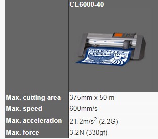
Here are the steps of the operation of the machine
1. The switch on button of the machine is on the left back side
2. The roll is provided to the machine from the back side where
there is a provision of mounting the cylinder on vinyll role.
3. The Vinyl sheet inserted should be parallel to the base of the machine
4. The Blade should be 0.2 mm outside the blade holder or you can test print some
shapes available on the machine interface itself.
5. It is therefore required to test print the shapes
using different forces and speed at a particular blade length to find out the
appropriate characteristic of the machine on which we can work.
6. The design made or exported will be send to the machine using the compatible software which in
this case is GRAPHTEC STUDIO.
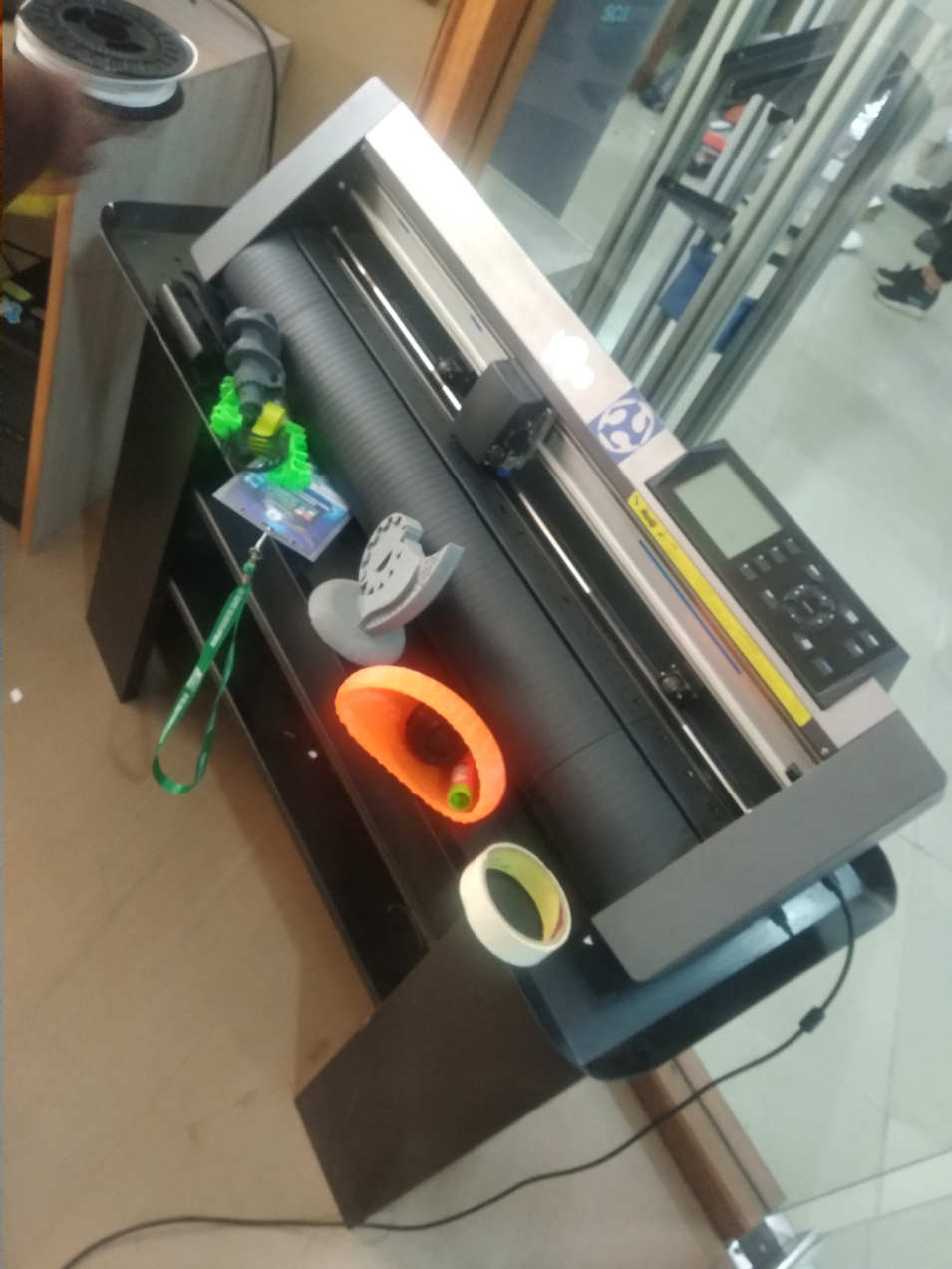
Machine availaible at our Fablab
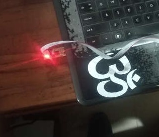
Initially some interesting stickers of batman, tortoise , OM are imported to the tool and worked upo
n using the Thresholds.
HOW TO SET PARAMETERS AND TEST CUT
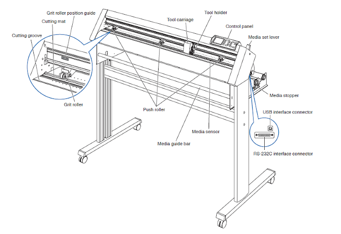
Setting the tool

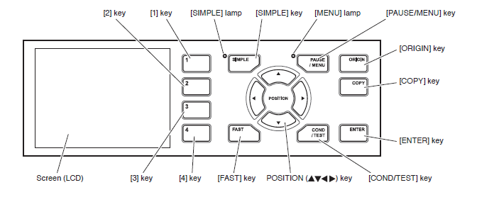
Control Panel
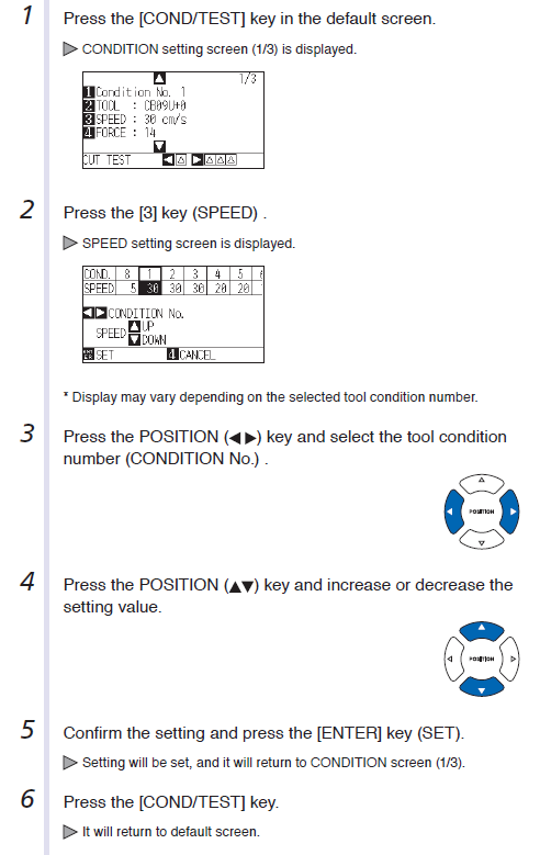
Setting the Parameters
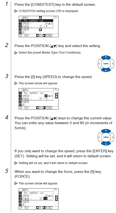
Setting the force value

Setting the Speed
Test Cut
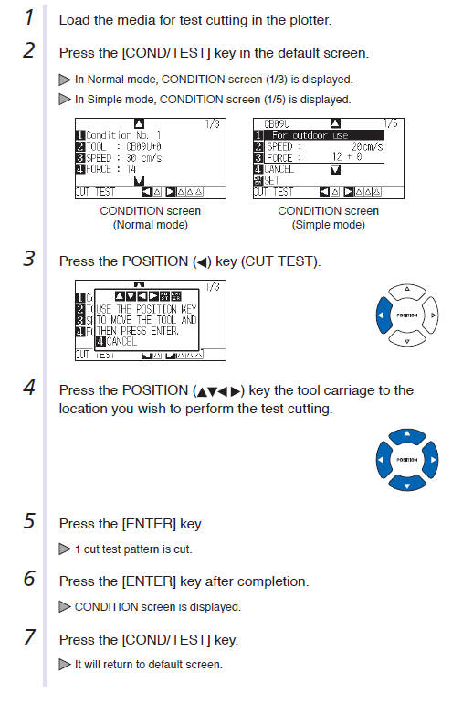
Test
Initially some test were performed to judge the optimum force and length of blade to cut the shape. The test cut
are present in machine as the three triangles inside a square. The test shape should be easily detachable from the sheet
and it should also not go to the bottom layer of the sheet. If the triangle edge is cut in such a way that the edges are off without any force
then it means that the force is more or the speed is less. We have to come to a trade off between the spped and the force
for the optimum characteristics.The optimum force in our case is 12 force and 10 speed .

Step 1:
Import the image
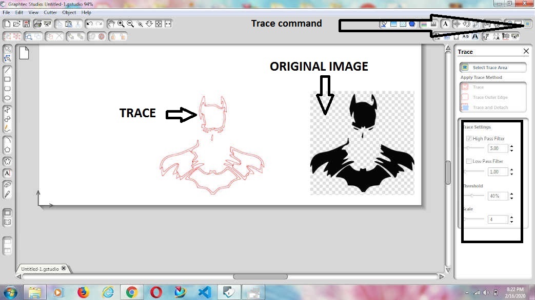
The image is to be imported to the software in my case, i have downloaded an image of Batman. It can be opened or can be dragged to the interface of the software. The basic commands of the software can be learnt using this link
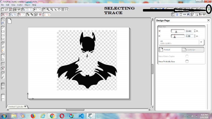
Step 2: Select the Trace Area
The trace area has to be selected and worked upon using the threshold settings.
High pass filter
It filters out or smooths the difference between the darker and lighter pixelsof the Bitmap and depending on the bitmap will grow or shrink the yellow tracing area.
Low Pass Filter
It removes noise in am image and it can reduce the sharpness in an image.
Threshold
It increases or decreases the sensitivity of the lighter colors when the high pass filter is applied.
Trace
It will trace both the inside and outside areas
Trace outer Edge
It will only trace the outline of the bitmap.
Trace and detach
It will trace and detach the yellow trace area of the bitmap from the untraced area of the bitmap.

Step 3:Play with the Threshold key
By increasing and decreasing the threshold and high pass filter and low pass filter
we can optmise the width of the lines.
When i did it for the first time i saw that there are two lines. which
are seen instead of one.Then i changed the figures to come out at an optimum level and then choosing the Trace option.
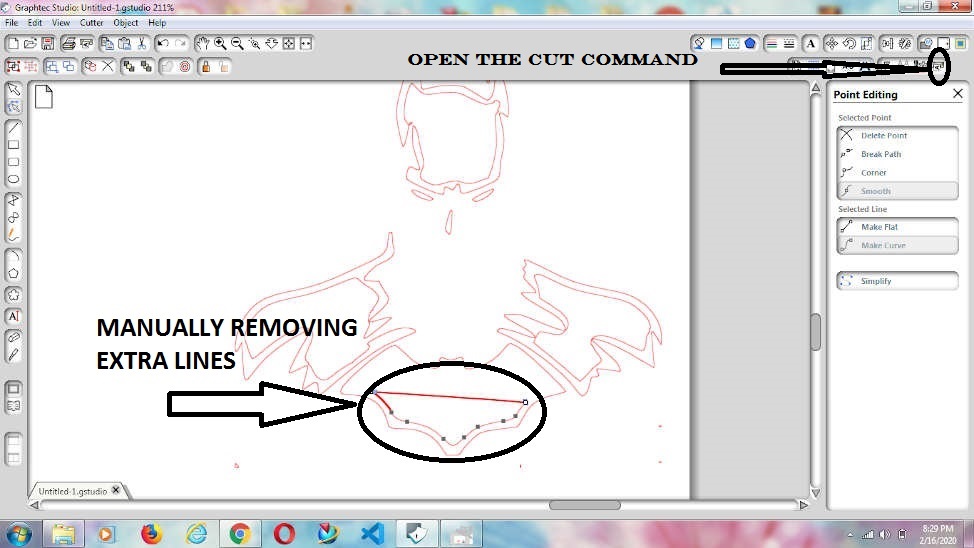
Step4: Edit the image as required
If the lines are not continous and after increasing the threshold , the proper alignment of the
drawing is not obtained then we can also edit the drawing by manually removing the double lines.
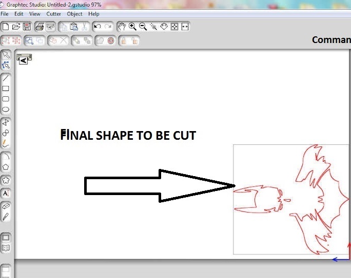
Step5: Send the Image to the Vinyl Plotter
Before sending the image to the plotter , we have to make sure that the origin is set. After the editing of the lines, the image can be sent to the machine by clicking an option of Send to cutter
        1. Lay your unweeded vinyl out on the table in a right-reading direction. Begin weeding from the upper right
         corner and work toward the lower left corner.

        2. When working with designs that are ½” or smaller, tape out the entire cut? The designs you need should
        come up with the vinyl in one piece. Lay this on your weeding area sticky side up and hold the vinyl in
        place using spring clamps. This will allow you to weed away the excess
        vinyl without causing any misalignment.

        3. Only cut a weeding border and no weeding lines, except the ones needed to separate groupings.
        Carefully weed out openings, such as the
        holes in the letters A, e and O. Cover the design in transfer tape like normal, carefully remove
        the backing paper and apply the design as
        usual. You should be able to remove the transfer tape and excess vinyl without the risk of damaging your design.

                                                                                                                ~ Source: https://www.thinksai.com/
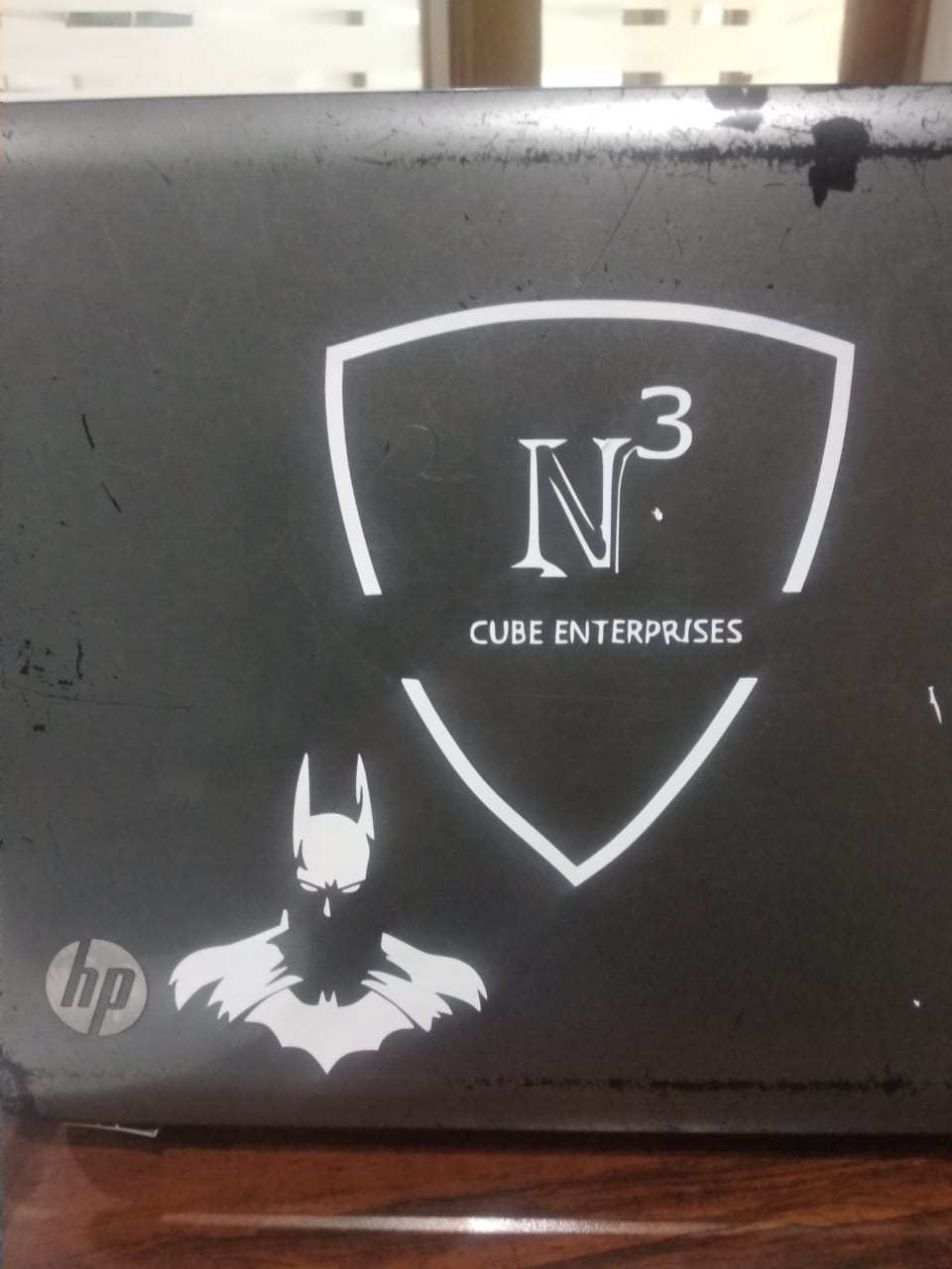
The sticker which i got after removing the unwanted lines form the trace area is this.
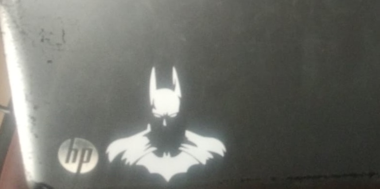
I also cut one more sticker for my laptop
Failures and Mistakes
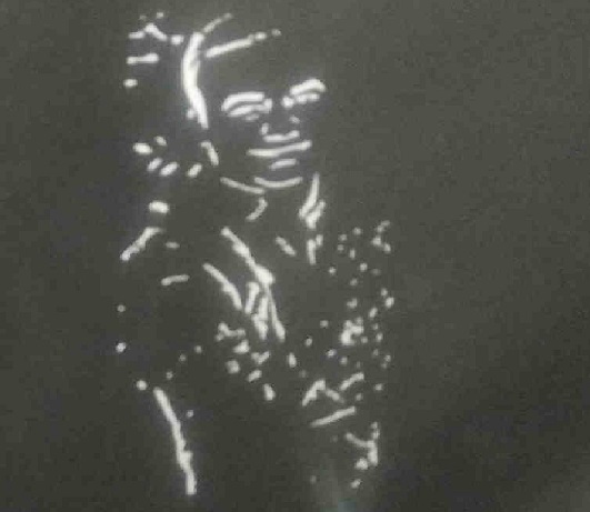
I also tried to make my own pic but the picture contained a lot of dots inside it
because of insufficient threshold level. Since the drawing had a lot of dots in it so the plotter also
took a lot ot time to complete it. I many times forgot to position the origin because of which
the part of the sheet was wasted. The alignment of the sheet is also important if the sheet is not properly aligned
then it will have resistance in moving forward at different strokes which are required for the completion of the sticker.
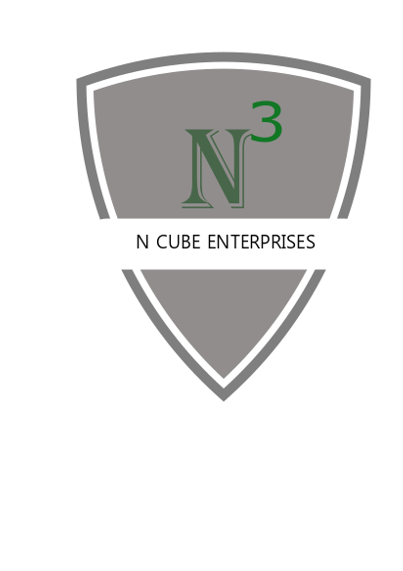
Created a logo using Inkscape
I wanted to make a logo and make a sticker of it. I used Inkscape since we already had a go with it
last week. I went through video tutorial to
learn some of the commands. The procedure i follwed is the same discusses above.
Laser Cutting machine
We have CO2 laser cutter machine in our fablab. The group assignment was to characterize the Laser focus
power, speed and kerf. CO2 laser cutting uses a focus
lens to gather CO2 laser beams on the material surface
to burn them. At the same time, the coaxial compressed
gas blows away the materials melt, making laser beams and
materials do relative motions along a certain path and forming a certain shape of cutting seam. Source Machinemfg.com

Laser cutter availaible at our Fablab
Initially i thought that itmust be very difficult to operate such a big machine
But as i got its working i found it the other way round.
The important thing is to keep in mind is that we are working with laser
and we have to take a lot of precautions.
Safety Precautions:
The laser cutter available in our fablab is of SIL.The specication of the machine is
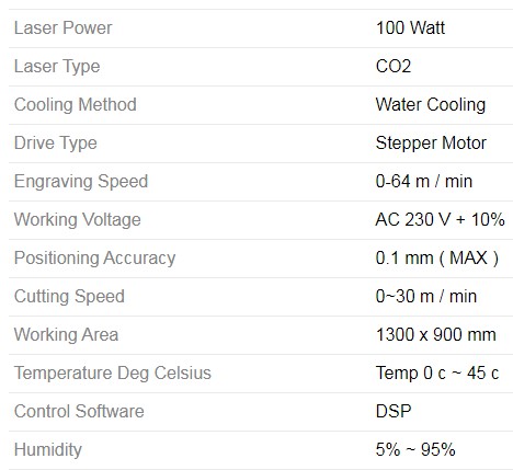
The main component system machine are
1.Bed 2.cooler 3. laser 4. polycarbonate sheet
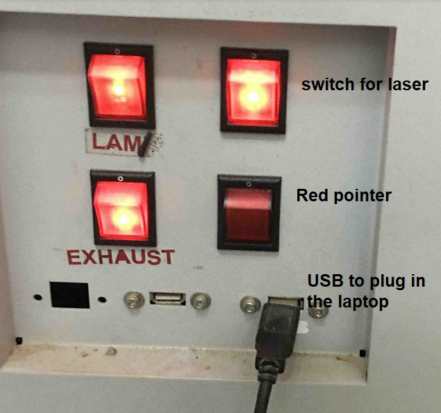
Four buttons are provided under right hand side. The buttons are for laser, point, exhaust and light.
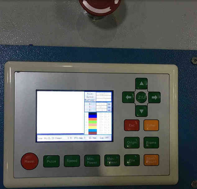
There is a controlling screen on the machine itself which facilitates movement of the bed up and down.
The full laser machine can be operated by inserting pendrive or by connecting the laptop to the machine.
Note:
It is important to converge the light to a point as it will concentrate the energy of the laser on that point and the cut will be clean and thin
Cooler is also installed which is there for cooling of the machine.
The water inside should be changed after every one week and it is important to operate the machine with cooler temp. up to or below 26 degree Celsius.
You can download RDworks software using this link
Setting the Laser machine
The machine has a CO2 laser which should be pointed on the cutting material. The laser pointer changes into two if the distance
between the laser slot and material is not proper. The laser is set by changing the length of the bed.
There are 4 buttons which are used to open the laser, pointer and the exhaust. The laser must be opened before giving command to the machine.
As the machine starts to follow the path even if the laser is off.
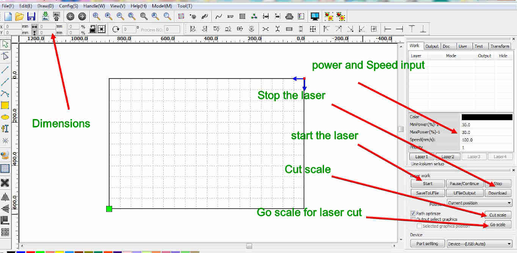
Working of RDworks
It is the software which is compatiblw with our laser machine. the interface is quite easy. you can import the .rld file and give the shape the requires powwr and speed
for cutting. And the laser cuts the material according to the input provided by the software.
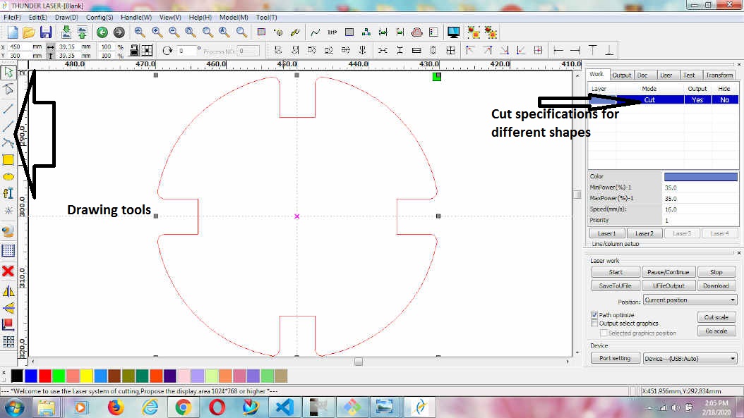
Kerf
Although the laser is extremely accurate and precise, the laser itself has a thickness, called a “kerf”.
Because the laser burns or vaporizes material, the kerf is the thickness of the portion of the material
that is lost when the laser cuts through.
For most applications of the laser cutter this is negligible, however in certain projects, adjusting the
drawing for the kerf of the laser may be necessary. For example, if a design has slot and fill components
that rely on friction of materials, adjusting for the kerf of the laser would be a good idea. Source:
nylasercut.com
Measuring Kerf
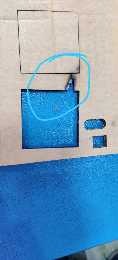
We first wanted to check kerf as it was important if we want design anything. we took a cardboard sheet and started cutting it with laser and suddenly we saw flames coming out of the cardboard. we stopped the cutting then reduced the power and and increased the speed to come up at the optimum value.
We ended up burning one square as we were not thorough with the specifications.
Initially we wanted to check the kerf at different speed and power. We ended up at optimum value
of power and speed for Cardboard.
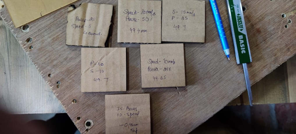
The value with minimum kerf obtained is Power=30 ans Speed=10.
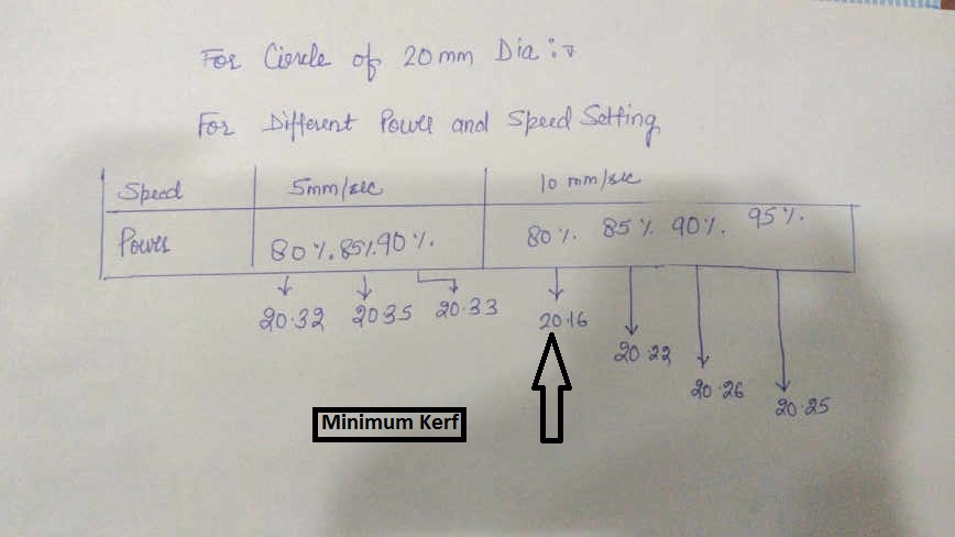
We then conducted the test on acrylic sheet at different speeds and power.The test design was such that we have used test cut?
with power varying from 80 to 95 and speed varying from 5 to 10. The cut was made at every speed and power
combinations. The minimum kerf obtained from the group of combinatons is with 80% power and 10 speed but if there are other
combinations of spped and power made availaible then the kerf obtained could also have been less than this.
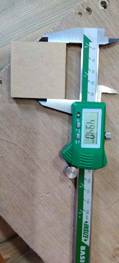
The minimum kerf was found in 80% percent power and 10 speed on acrylic sheet of 3mm thickness
The readings were recorded
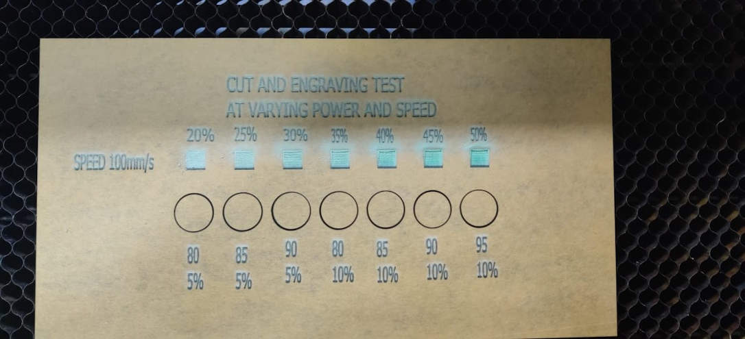
We then went ahead to have the engraving test on acrylic sheet.
The design was made on the RDworks software itself by PULKIT and we have to give the specication of cutting and speed
to eacn and every square. Since the colors availaible on RDWorks software are limited so the settings were provided to the software
horizontally. It took more than an hour to engrave all the rectangles.
As we can see from the image of the engraving
test conduted, we can see that the engraving converted to complete cut at some power speed combinations which was not required.
As the speed is increased, the depth of engraving is reduced at the same power input. But at the same speed and
increasing the power increases the depth of engraving. The engraving converted to complete and thorough cut at 20 and 40 speed with power more than 30.
so it is important to keep in mind what is the charecteristic at which we should work on.
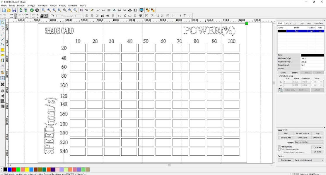
Shade card design on RDWORKS

Parametric Design
parametric design involves engineers building up a 3D geometry piece by piece. 2D sketches turn into 3D features, with constraints and relations duly applied to fit the designer’s intent. However, since each step follows from preceding steps, parametric design can require careful planning. The feature-based parametric modeling technique enables the designer to incorporate the original design intent into the construction of the model. The word parametric means the geometric definitions of the design, such as dimensions, can be varied at any time in the design process. Parametric modeling is accomplished by identifying and creating the key features of the design with the aid of computer software. The design variables, described in the sketches and described as parametric relations, can then be used to quickly modify/update the design.
Then we proceeded to make our individual assignments.
I designed some shapes for press fit on NX and
then exported them in DXF form to RDworks software and then made the cut.
Source: Engineering.com
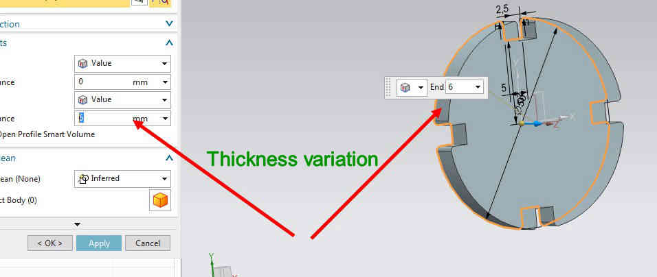
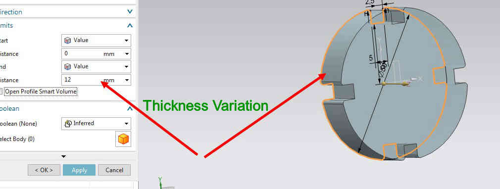
Compensation for the KERF
As the kerf came out to be 0.3mm at 30 power and 10 speed, so it was taken care of in the parametric design of the components. The slots made for press fit kit were changed as the slot length in the design was taken to be 5mm and the thickness of the cardboard was 5.3 mm. Since the design made is parametric so by changing one parameter, the whole design can be changed. The slots size were made considering the kerf of 0.3 mm for 5.3 mm cardboard.
The shapes are made on Nx11 to ensure the parametric design consideration. The design is made in such a way that the parameters can be changed as per the
requiremnt of the designer.
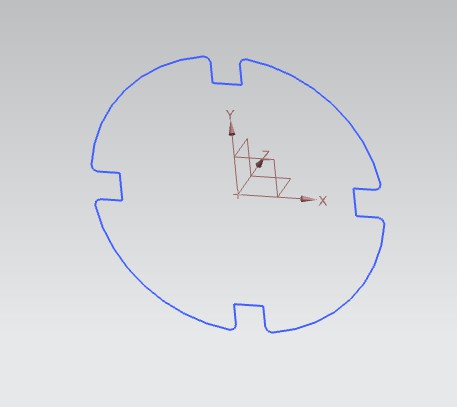

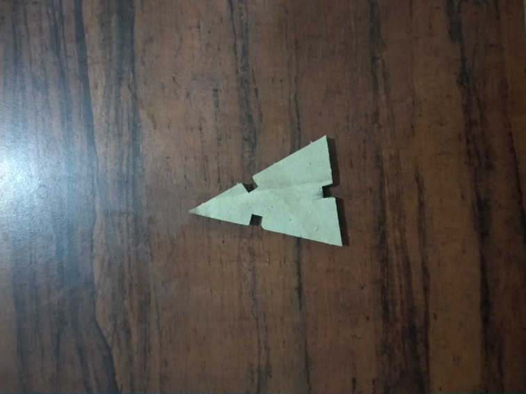
Triangle, square and cirlces shapes are designed on NX11 software and are exported to RDworks and then cut out
by using the laser cutter.
I tried to make various forms by using press fit.
These are the shapes which are obtained through laser cutter
Download Rdworks File
Download all Design NX files

The problem which i experienced working with cardboard is that it is difficult to find perfect horizontal pieces of cardboard which makes the laser travel through different depth and whcih results in different value of kerf and the pointer of the laser can also touch the cardboard. This problem is not there with Acrylic sheet as they are completely horizontal.
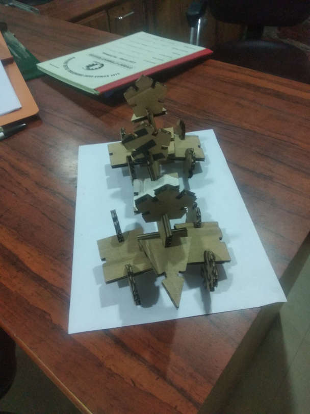
Pressfit kit
The different shapes are cut from the RDworks software and are joined to make pressfit kit. the slots are cut keeping in consideration that the fit is not loose and because of this the pressfit kits are strong enough.

The pressfit is easy in case of cardboard due to different thickness and roughness at its edges. We should keep in mind that the slots cut should not be greater than the thickness of the material. There is a
Hero Shot of the pressfit Kit
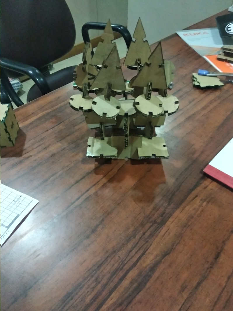
Initially I tested with two circle shapes. And i found that the fit was proper with 5mm depth.
Then I continued with the same settings.
Download all Design NX files