NETWORKING AND COMMUNICATION
This week we have a group assignment and an individual assignment .
The group assignment for this week is to send a message between two projects .
The individual assignment for this week is to design, build, and connect wired or wireless node(s) with network or bus addresses .
The goal for this week is to learn about the network and communications, and to learn how to connect two circuits either
wireless or with wires using so many Techniques such as bluetooth modules, radio modules and wifi modules.
This week also I am short of the equipments required to do the job. So I have used tinkercad through which simulation is shown where 3 arduino boards are connected and the one is acting as the Master and the other 2 are acting as the slave.
Networking and communication is very new to me. So i started with reading pages of previous fab academy students.
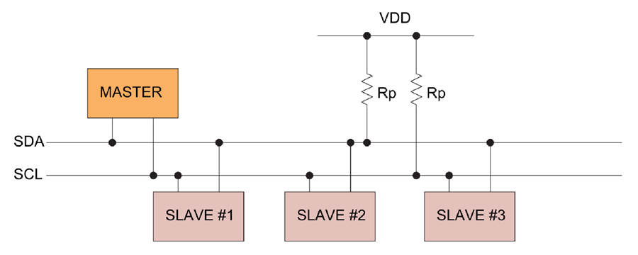
I2C Protocol
The Inter-integrated Circuit (I2C) Protocol is a protocol intended to allow multiple “slave” digital integrated circuits (“chips”) to communicate with one or more “master” chips. Like the Serial Peripheral Interface (SPI), it is only intended for short distance communications within a single device. Like Asynchronous Serial Interfaces (such as RS-232 or UARTs), it only requires two signal wires to exchange information.
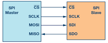
SPI PROTOCOL
The most obvious drawback of SPI is the number of pins required. Connecting a single master to a single slave with an SPI bus requires four lines; each additional slave requires one additional chip select I/O pin on the master. The rapid proliferation of pin connections makes it undesirable in situations where lots of devices must be slaved to one master. Also, the large number of connections for each device can make routing signals more difficult in tight PCB layout situations. SPI only allows one master on the bus, but it does support an arbitrary number of slaves (subject only to the drive capability of the devices connected to the bus and the number of chip select pins available).
UART PROTOCOL
 Stands for Universal Asynchronous Reception and Transmission (UART)
Simple serial communication protocol that allows the host communicate with the auxiliary device.
UART supports bidrectional, asynchronous and serial data transmission.
It has two data lines, one to transmit (TX) and another to receive (RX) which is used to communicate through digital pin 0, digital pin 1.
TX and RX are connected between two devices. (eg. USB and computer)
UART can also handle synchronization management issues between computers and external serial devices.
INDIVIDUAL ASSIGNMENT
I have used TINKERCAD software to do the simulation and i used 3 arduino boards with one as master and the other two as slaves and used I2C communication protocol.
The code for the Master Arduino is
  #include "Wire.h"

void setup()
{
  Wire.begin();
}

void loop()
{
  Wire.beginTransmission(1);
  Wire.write('H');
  Wire.endTransmission();

  delay(500);

  Wire.beginTransmission(1);
  Wire.write('L');
  Wire.endTransmission();

  delay(500);

  Wire.beginTransmission(2);
  Wire.write('H');
  Wire.endTransmission();

  delay(500);

  Wire.beginTransmission(2);
  Wire.write('L');
  Wire.endTransmission();

  delay(500);
}
The code for the Slave 1 is
  #include "Wire.h"

const byte slaveId = 1;

void setup()
{
  Wire.begin(slaveId);
  Wire.onReceive(receiveEvent);

  pinMode(13,OUTPUT);
  digitalWrite(13,LOW);
}

void loop()
{
}

void receiveEvent(int howMany)
{
  char inChar;

  while(Wire.available() > 0)
  {
    inChar = Wire.read();

    if (inChar == 'H')
    {
      digitalWrite(13, HIGH);
    }
    else if (inChar == 'L')
    {
      digitalWrite(13, LOW);
    }
  }
}
The code for the slave 2 is
  #include "Wire.h"

const byte slaveId = 2;

void setup()
{
  Wire.begin(slaveId);
  Wire.onReceive(receiveEvent);

  pinMode(13,OUTPUT);
  digitalWrite(13,LOW);
}

void loop()
{
}

void receiveEvent(int howMany)
{
  char inChar;

  while(Wire.available() > 0)
  {
    inChar = Wire.read();

    if (inChar == 'H')
    {
      digitalWrite(13, HIGH);
    }
    else if (inChar == 'L')
    {
      digitalWrite(13, LOW);
    }
  }
}
After the lockdown we have tried to upload the program on three arduinos and communicate between them through I2C COMMUNICATION.
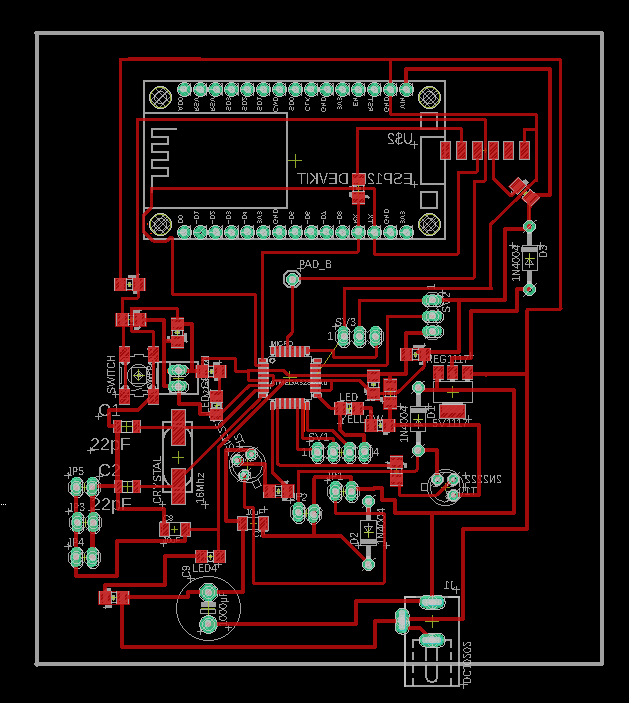
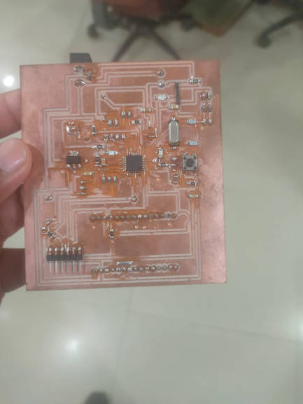
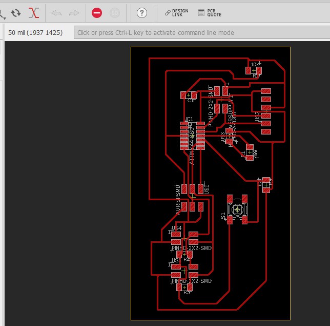
I designed the board in the elctronic design week so that it can be used for other assignmenst as well so for this week i am going to do UART communication between the board i desinged and the board i already designed for my final project.
I have also done the same communication between the final project boards of all the three projects.
The master board must have 2 pairs of RX TX where one will be connected to the FTDI( in our case it is arduino board) and the other pair of RX TX has to be connected to the slave board for the communication.
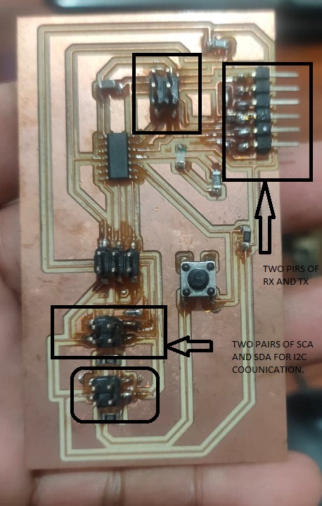
While uploading the code it very important to see the coonections which we are doing. The mistake which i made was that i uploaded a program for my board with wrong RX and TX pins and then after seeing all the steps i relaised that the board which i have made for my final project has different RX and TX pins then i have given in my program.
Since here we are using arduino as the FTDI so it is imporatnt to have strong connections through jumpers because sometimes it happens that the wires are seen as they are inside the hole but they are not. So we need to be cautious about it.
Code for the boards
/*This work by NEERAJ GUPTA is licensed under a Creative Commons
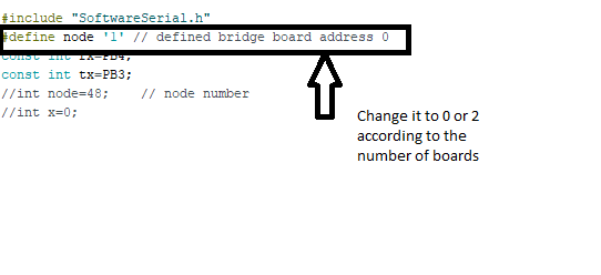
Attribution-ShareAlike 4.0 International License.*/ #include "SoftwareSerial.h" #define node '1' // defined bridge board address 0 const int rx=3; const int tx=4; //int node=48; // node number //int x=0; // the setup function runs once when you press reset or power the board SoftwareSerial mySerial(rx, tx); void setup() { // initialize digital pin 13 as an output. mySerial.begin(9600); pinMode(PB0, OUTPUT); digitalWrite(PB0, HIGH); } // the loop function runs over and over again forever void loop() { if(mySerial.available() > 0) { //mySerial.print("here"); int x=mySerial.read(); delay(1000); // mySerial.print(x); if (x==node) { digitalWrite(PB0, LOW); // turn the LED on (HIGH is the voltage level) delay(500); digitalWrite(PB0, HIGH); delay(500); } } }
Serial Communication between Arduino UNO and NODEMCU
Since i am going to use NODEMCU in my project which will be integrated to my board so i have made a serial communication between arduino uno and nodemcu.
Code for Arduino UNO
  void setup() {
  Serial.begin(9600);

}

void loop() {
Serial.println("Arduino bol raha huin");
delay(500);
}
I am printing a message on the serial monitor for the arduino uno and that msg will be sent to arduino uno through serial communication
Code for NODEMCU
  #include "SoftwareSerial.h"
SoftwareSerial mySerial (D1, D2);
void setup() {
 Serial.begin(115200);
 mySerial.begin(9600);

}

void loop() {
  String msg = mySerial.readStringUntil('\r');

  Serial.println(msg);

}
The hardware serial baud rate for NODEMCU is set to 1152000 and the software serial is same for both arduino and nodemcu which is 9600. The msg will be stored as the string type and will be displayed on the serial monitor of Nodemcu as soon as it comes on the serial port.
Through software serial library we can make number of pins for recieving and transmiison. In the present case i have used D1 and D2 as software serial however i could also have used the builtin RX and TX of Nodemcu.
It is required to leave the RX and TX pins of arduino uno if they are used for transmission and reciving. If the pins are busy then the program will not be uploaded on the board.
Use of USB to TTL Convertor
Serial Communication between Satshakit board and Nodemcu
Code for my Board
  #include "SoftwareSerial.h"
SoftwareSerial myySerial (3, 4);
void setup() {
  myySerial.begin(9600);

}

void loop() {
myySerial.println("Arduino bol raha huin");
delay(500);
}
Code for Nodemcu
  #include "SoftwareSerial.h"
SoftwareSerial mySerial (D1, D2);
void setup() {
 Serial.begin(115200);
 mySerial.begin(9600);

}

void loop() {
  String msg = mySerial.readStringUntil('\r');

  Serial.println(msg);

}
The difference between the arduino uno and my satshakit board is that i have given pin 3 and 4 for serial communication and all other things are same. The SoftwareSerial library has been developed to allow serial communication on other digital pins of the Arduino, using software to replicate the functionality (hence the name "SoftwareSerial"). It is possible to have multiple software serial ports with speeds up to 115200 bps. A parameter enables inverted signaling for devices which require that protocol.
Sending Data to Thingspeak from Nodemcu
In my project i want to display my data on a web browser for whcih i have used Thingspeak. "ThingSpeak is an open-source Internet of Things (IoT) application and API to store and retrieve data from things using the HTTP and MQTT protocol over the Internet or via a Local Area Network. ThingSpeak enables the creation of sensor logging applications, location tracking applications, and a social network of things with status updates.
so i will be using nodemcu which has a built in wifi and bluetooth and then i will send the data to thingspeak channel. the creation of chaneel is a easy task which i have explained in the later part of this page.
The code for Nodemcu requires you to put the wifi user name and password and the API key of the channel.
I have used the DHT11 sensor and i am putting the data collected by nodemcu to put up in the Thnkspeak channel.
Code for Nodemcu
  #include "DHT.h"
#include "ESP8266WiFi.h"

String apiKey = "NMIGD6AZW903W0D7";     //  Enter your Write API key from ThingSpeak

const char *ssid =  "Neeraj";     // replace with your wifi ssid and wpa2 key
const char *pass =  "darshika";
const char* server = "api.thingspeak.com";

#define DHTPIN 0          //pin where the dht11 is connected

DHT dht(DHTPIN, DHT11);

WiFiClient client;

void setup()
{
       Serial.begin(115200);
       delay(10);
       dht.begin();

       Serial.println("Connecting to ");
       Serial.println(ssid);


       WiFi.begin(ssid, pass);

      while (WiFi.status() != WL_CONNECTED)
     {
            delay(500);
            Serial.print(".");
     }
      Serial.println("");
      Serial.println("WiFi connected");

}

void loop()
{

      float h = dht.readHumidity();
      float t = dht.readTemperature();

              if (isnan(h) || isnan(t))
                 {
                     Serial.println("Failed to read from DHT sensor!");
                      return;
                 }

                         if (client.connect(server,80))   //   "184.106.153.149" or api.thingspeak.com
                      {

                             String postStr = apiKey;
                             postStr +="&field1=";
                             postStr += String(t);
                             postStr +="&field2=";
                             postStr += String(h);
                             postStr += "\r\n\r\n";

                             client.print("POST /update HTTP/1.1\n");
                             client.print("Host: api.thingspeak.com\n");
                             client.print("Connection: close\n");
                             client.print("X-THINGSPEAKAPIKEY: "+apiKey+"\n");
                             client.print("Content-Type: application/x-www-form-urlencoded\n");
                             client.print("Content-Length: ");
                             client.print(postStr.length());
                             client.print("\n\n");
                             client.print(postStr);

                             Serial.print("Temperature: ");
                             Serial.print(t);
                             Serial.print(" degrees Celcius, Humidity: ");
                             Serial.print(h);
                             Serial.println("%. Send to Thingspeak.");
                        }
          client.stop();

          Serial.println("Waiting...");

  // thingspeak needs minimum 15 sec delay between updates
  delay(1000);
Please replace "" with <> in the code.
Thingspeak
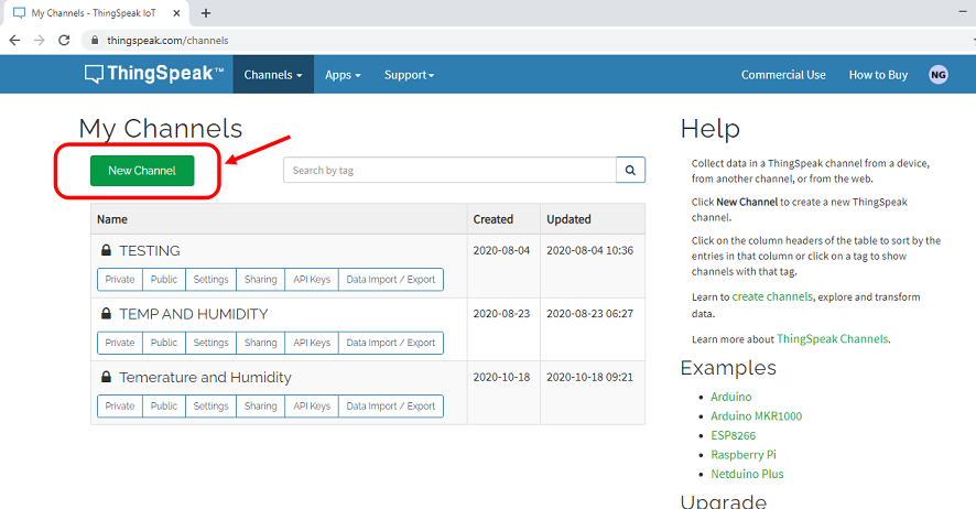
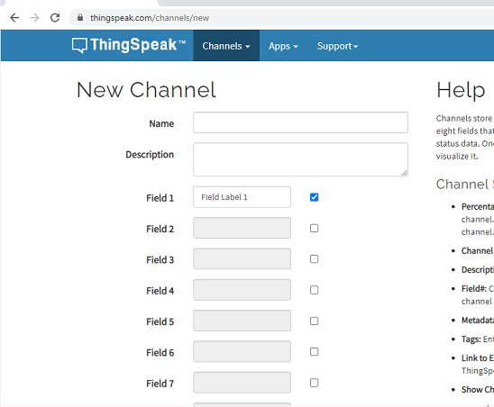
To create the channel, you just need to register and login with your credentials. in the homepage itself you will see the icon to craete the channel.
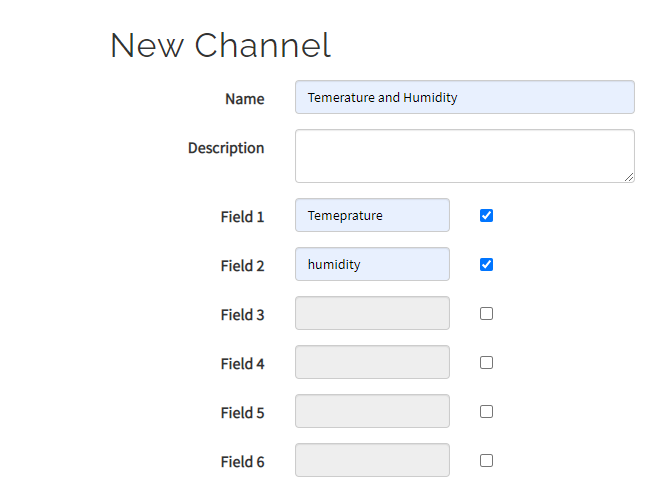
Then put the name off the channel and also the number of fields you want to utilize. Like in my case i will be usinmh the temperatute and humidity fields so i require two.
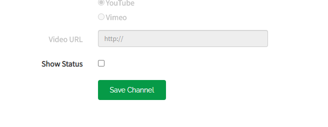
Put the name of the channel and click on the save button/
As you craete the channel, you will see some credentials like channel Id.
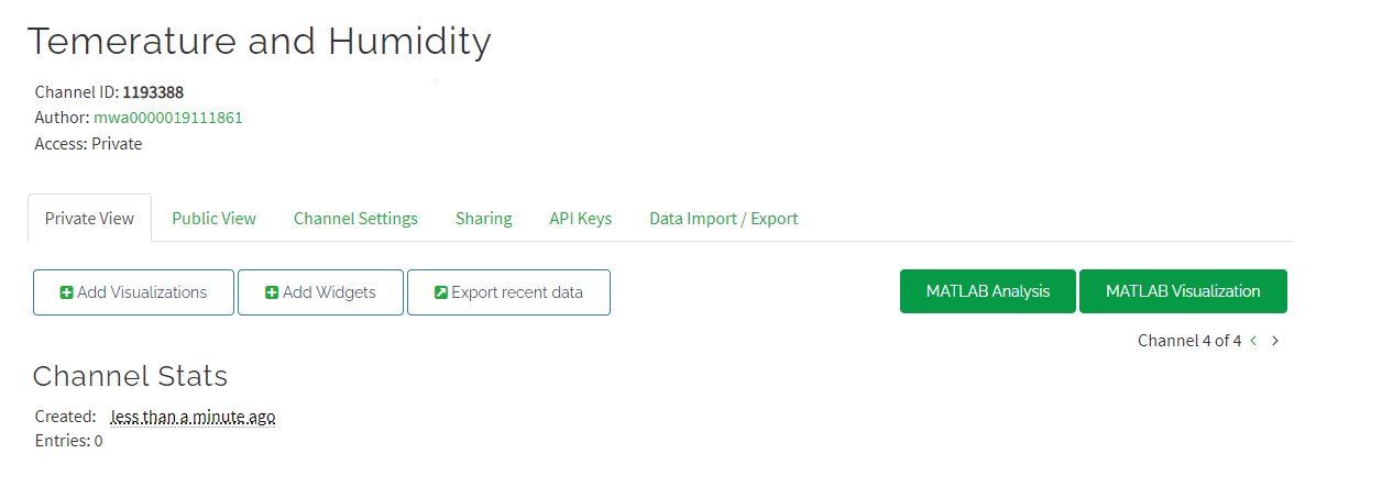
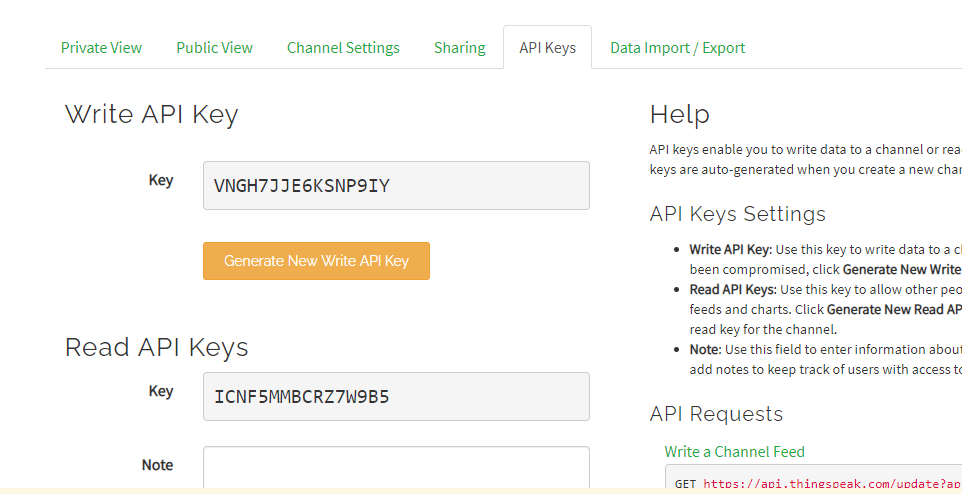
You can see the API key which is to be put in the arduino code by clicking on the API keys icon.
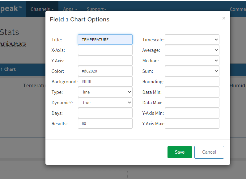
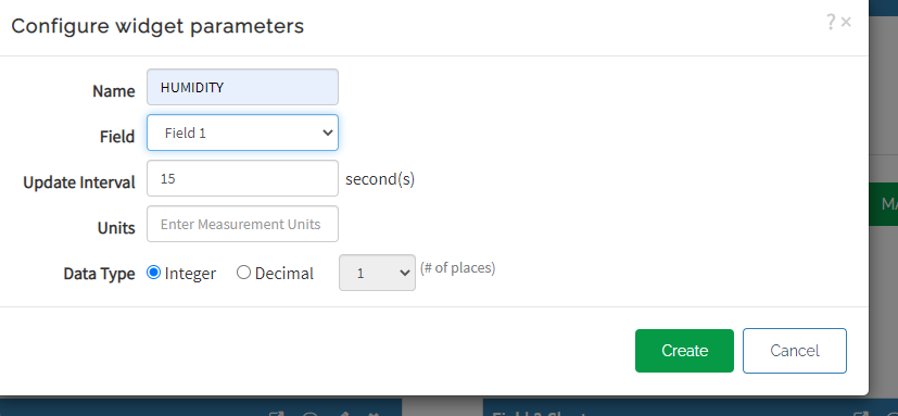
you need to name the foeld name as well and you can also add widget tool as well.
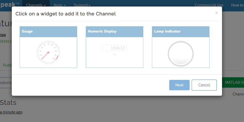
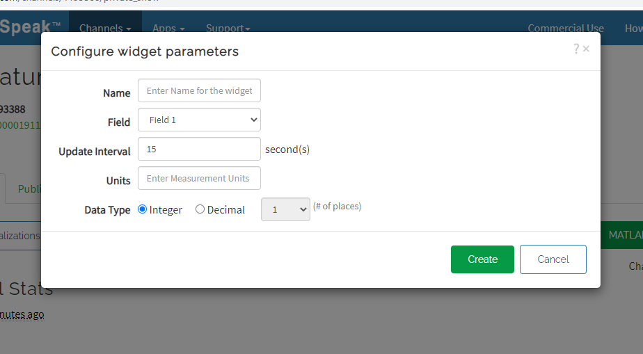
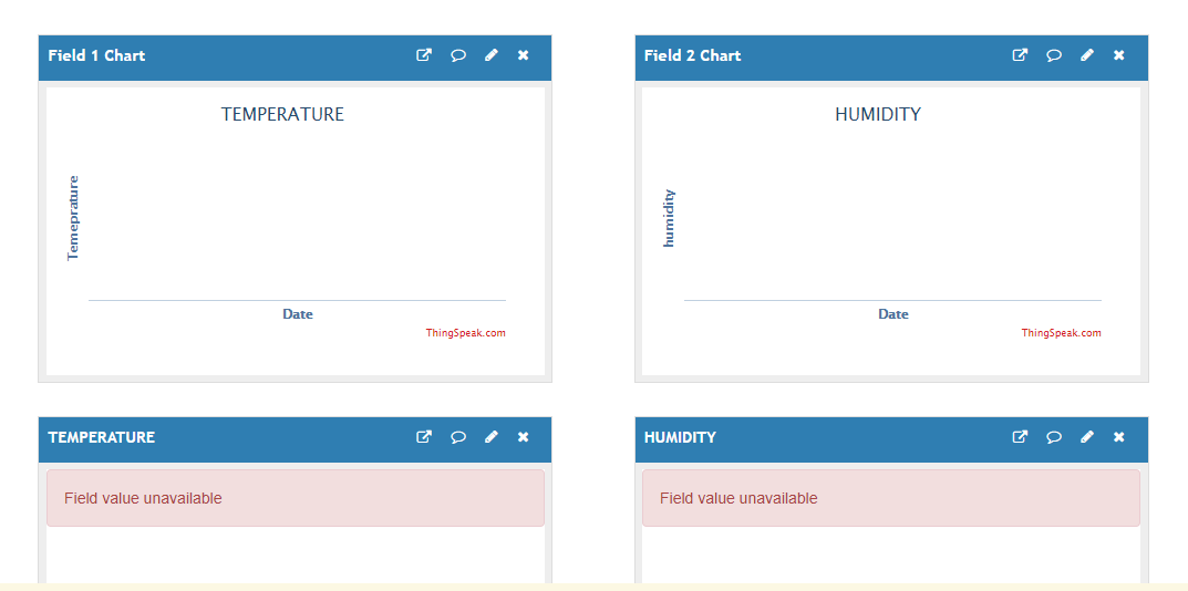
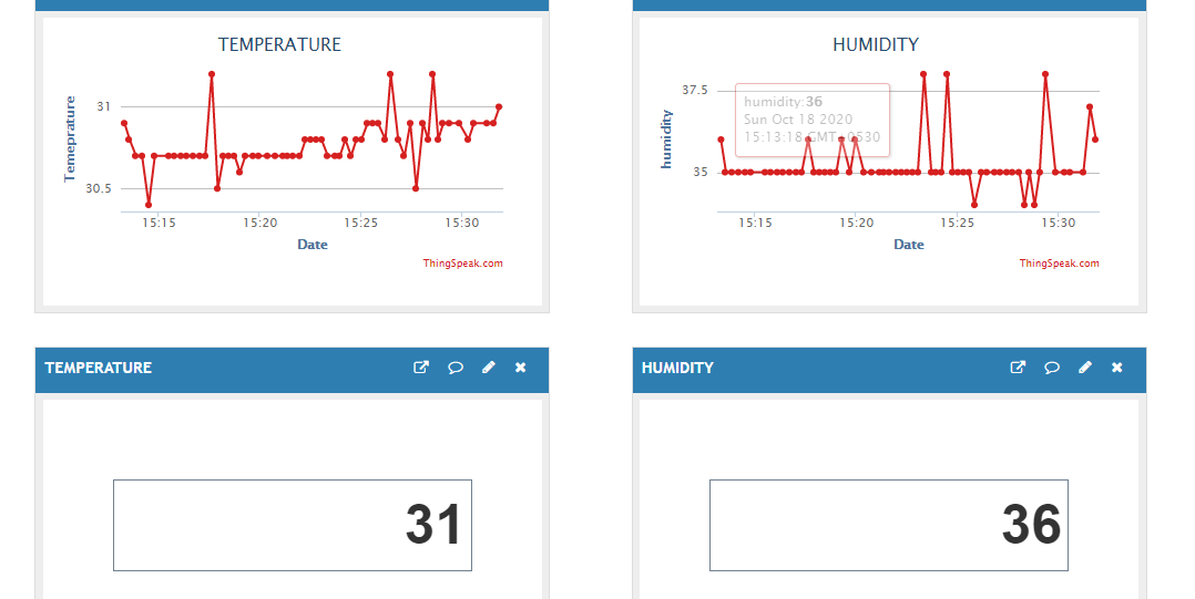
So there are two fields whcih are created and the other two will show the results in numeric form.
as soona s you upload the code you can see the value starts to appear on your serial monitor and those vales are trasnfereed to the thingspeak channel
Group Assignment
Our PCBs of the final projects were ready so we thought of programming our boards to make a communication between them. We used the same code as uploded in the individual assignment and a communication between the boards were achieved. Again it is important to have the exact value that you must put for the RX and TX pins becuase these are the pins responsible for the communication between the boards.
NETCAT
Netcat is a computer networking utility for reading from and writing to network connections using TCP or UDP.
The command is designed to be a dependable back-end that can be used directly or easily driven by other programs and scripts.
At the same time, it is a feature-rich network debugging and investigation tool, since it can produce almost any kind of connection its user could need and has a number of built-in capabilities.