INTERFACE AND APPLICATION PROGRAMMING
- Group Assignment
compare as many tool options as possible - Individual Assignment
write an application that interfaces a user with an input and/or output device that you made
This week we are going to make an app and will control the device using that app only. I am excited to make the app. We have been introduced to many languages in the Neil's Session and i am going to try with MIT App Inventor and Python.
MIT App Inventor
I went through a tutorials about the basics of this software and i found Tutoralvery helpful to undertand the basics of the app.
So i am going to make an app which will turn an led on and off with the use of an APP.
since i do not have any hardware and nor the simulator tool for such an assignment so i am going to write the code which will be there to on and off the led.
The code is
// Include Libraries
#include "Arduino.h"
#include "BTHC05.h"
#include "LED.h"
// Pin Definitions
#define BTHC05_PIN_TXD 11
#define BTHC05_PIN_RXD 10
#define LEDB_PIN_VIN 5
// Global variables and defines
// object initialization
BTHC05 bthc05(BTHC05_PIN_RXD,BTHC05_PIN_TXD);
LED ledB(LEDB_PIN_VIN);
// define vars for testing menu
const int timeout = 10000; //define timeout of 10 sec
char menuOption = 0;
long time0;
// Setup the essentials for your circuit to work. It runs first every time your circuit is powered with electricity.
void setup()
{
// Setup Serial which is useful for debugging
// Use the Serial Monitor to view printed messages
Serial.begin(9600);
while (!Serial) ; // wait for serial port to connect. Needed for native USB
Serial.println("start");
bthc05.begin(9600);
bthc05.println("Bluetooth On....");
menuOption = menu();
}
// Main logic of your circuit. It defines the interaction between the components you selected. After setup, it runs over and over again, in an eternal loop.
void loop()
{
if(menuOption == '1') {
// HC - 05 Bluetooth Serial Module - Test Code
String bthc05Str = "";
//Receive String from bluetooth device
if (bthc05.available())
{
//Read a complete line from bluetooth terminal
bthc05Str = bthc05.readStringUntil('\n');
// Print raw data to serial monitor
Serial.print("BT Raw Data: ");
Serial.println(bthc05Str);
}
//Send sensor data to Bluetooth device
bthc05.println("PUT YOUR SENSOR DATA HERE");
}
else if(menuOption == '2') {
// LED - Basic Blue 5mm - Test Code
// The LED will turn on and fade till it is off
for(int i=255 ; i> 0 ; i -= 5)
{
ledB.dim(i);
// 1. Dim Led
delay(15);
// 2. waits 5 milliseconds (0.5 sec). Change the value in the brackets (500) for a longer or shorter delay in milliseconds.
}
ledB.off();
// 3. turns off
}
if (millis() - time0 > timeout)
{
menuOption = menu();
}
}
// Menu function for selecting the components to be tested
// Follow serial monitor for instrcutions
char menu()
{
Serial.println(F("\nWhich component would you like to test?"));
Serial.println(F("(1) HC - 05 Bluetooth Serial Module"));
Serial.println(F("(2) LED - Basic Blue 5mm"));
Serial.println(F("(menu) send anything else or press on board reset button\n"));
while (!Serial.available());
// Read data from serial monitor if received
while (Serial.available())
{
char c = Serial.read();
if (isAlphaNumeric(c))
{
if(c == '1')
Serial.println(F("Now Testing HC - 05 Bluetooth Serial Module"));
else if(c == '2')
Serial.println(F("Now Testing LED - Basic Blue 5mm"));
else
{
Serial.println(F("illegal input!"));
return 0;
}
time0 = millis();
return c;
}
}
}
After Lockdown
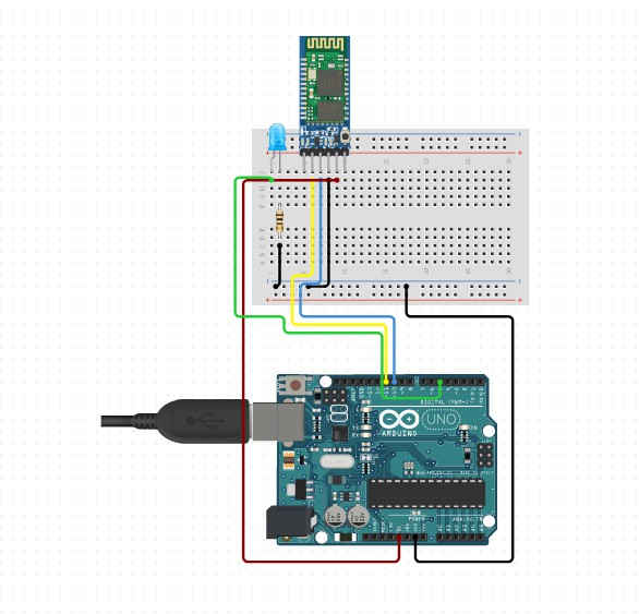
I had tried to make an app in the lockdown to blink an led on an arduino uno through MIT APP INVENTOR. And i got to know that it is not a difficult thing to crate an app. So now i am going to make an app which will blink the LED on the Arduino board and the board made in the electronic design week. You can see the design of my board on this Page .
So to make an app which talks to your board you need to use a bluetooth module. The bluetooth module will take the command given through the app to your board. The Transmitter and reciver pins (RX and TX) are responsible for the communication of the data and we also call it as UART communication.
So to make the board understand what command it is getting serially and what to do after getting the command, for that you need to program the board before or after making the app.
CODE FOR ARDUINO BOARD
  /*This work by NEERAJ GUPTA is licensed under a Creative Commons Attribution-ShareAlike 4.0 International License.*/
    char Incoming_value = 0;

void setup()
{
  Serial.begin(9600);
  pinMode(13, OUTPUT);
}

void loop()
{
  if(Serial.available() > 0)
  {
    Incoming_value = Serial.read();
    Serial.print(Incoming_value);
    Serial.print("\n");
    if(Incoming_value == '1')
      digitalWrite(13, HIGH);
    else if(Incoming_value == '0')
      digitalWrite(13, LOW);
  }
}
The code asks the board to activate the Built in LED at Digital Pin 13 if it sees any data coming to its serial port. If the value coming is 1 then it will switch on the LED and if the command is coming to the serial port is zero then it will switch off the LED.
MIT APP INVENTOR
MIT App Inventor is a web application integrated development environment originally provided by Google, and now maintained by the Massachusetts Institute of Technology (MIT). It allows newcomers to computer programming to create application software(apps) for two operating systems (OS): Android, and iOS. It is free and open-source software released under dual licensing: a Creative Commons Attribution ShareAlike 3.0 Unported license, and an Apache License 2.0 for the source code. Source:WIKIPEDIA.
You need to browse this page to come to the home page of MIT APP INVENTOR.
This tutorial helped me learn to build the app and also understand the application.
Thr process of making an app is explained
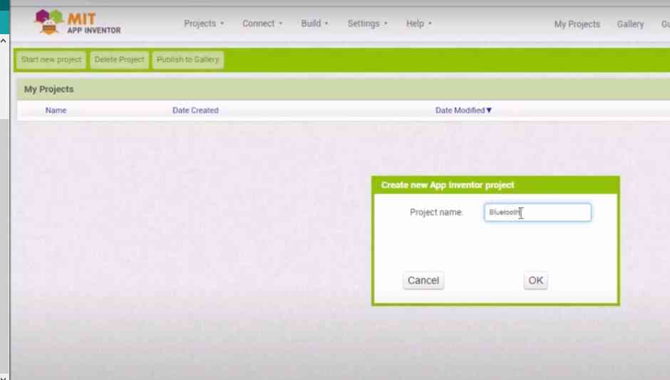
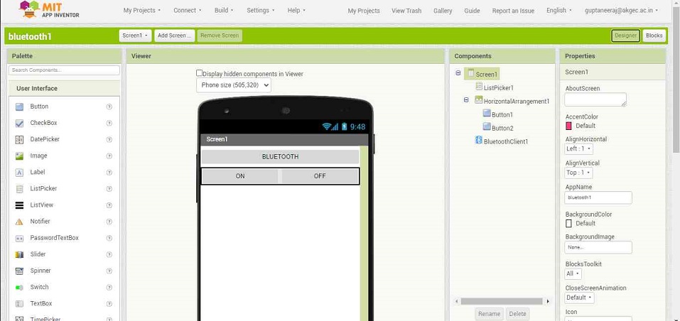
Step1: Open the site and start a project
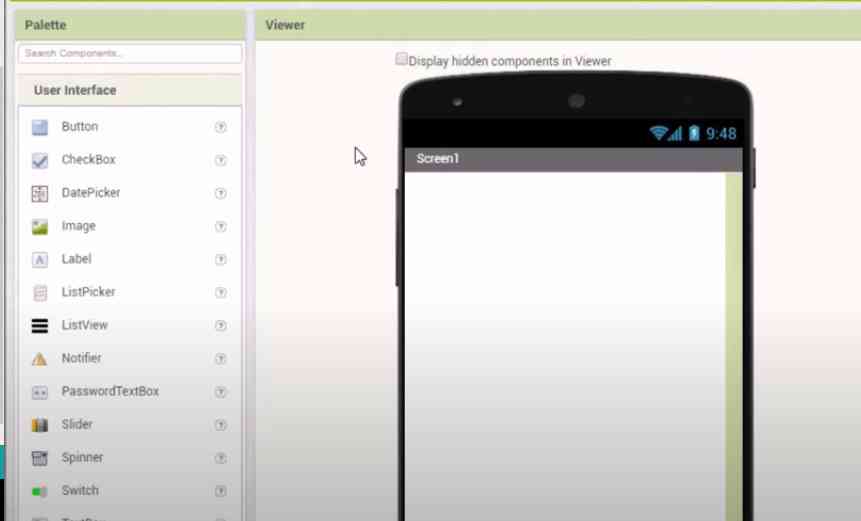
Step2: Use the user interface icons on the left to design the butons.
Step3: While making the interface you can change the dimesions of the button and colour and a lot of things from the settings itself.
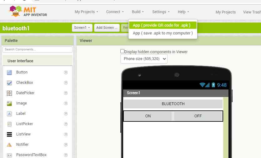
step 4 :Then you ned to install an app for scaonning the QR code for the app made by you. That app is MIT AI2 Companion.
The build icon lets you generate the QR code
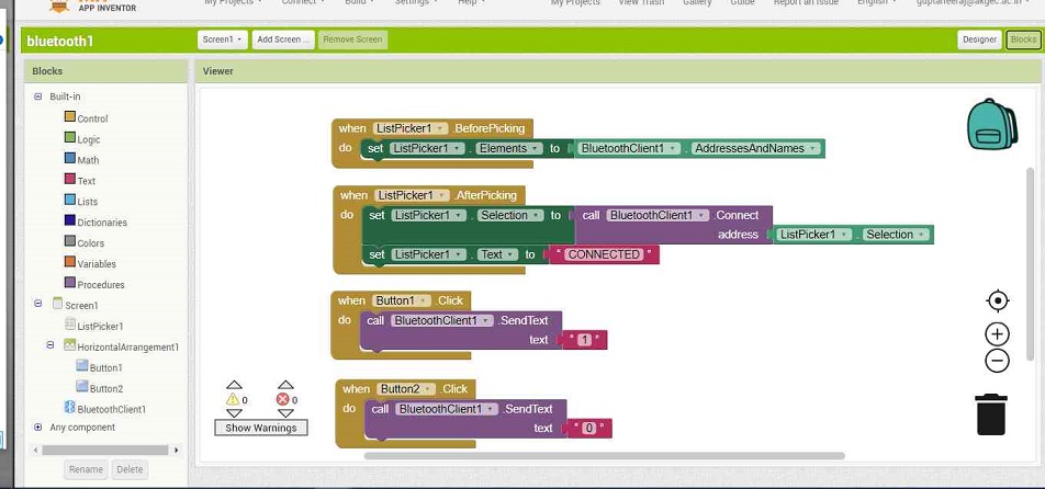
The programming tells the app what to do and how to do for that you need to click the blocks icon on the right side of the page.
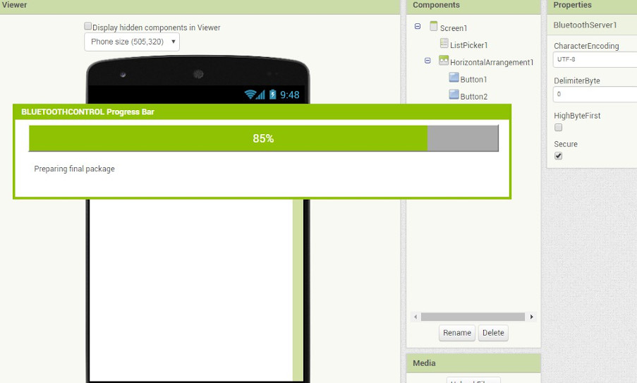
As you click on the build QR code then you will see some progress bars completing.
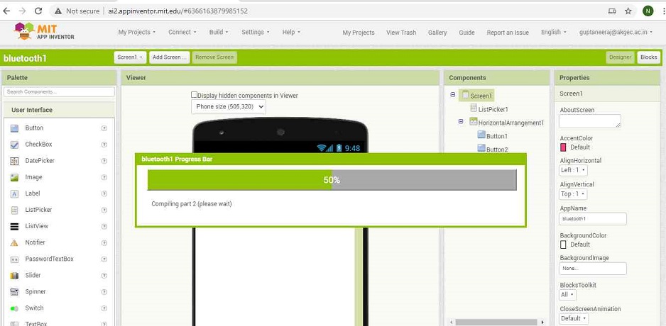
The QR scan code will be cisible on the screen and then you need to scan it through MIT AI2 companion app and a file will be loaded and will ask you to download it on your mobile phone.
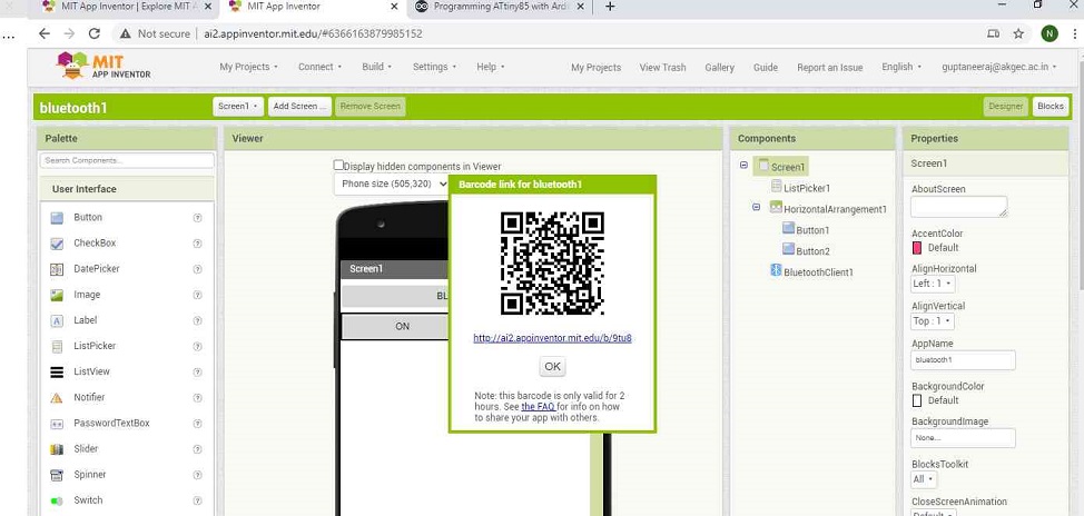
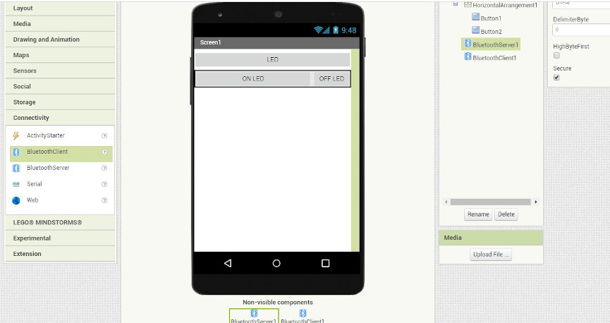
As you download the file and install the app, you will see the same screen og the app on your
Explaination of the code of MIT app Inventor
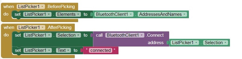
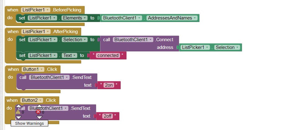
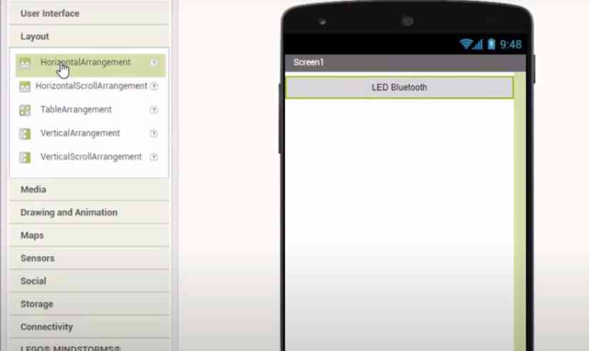
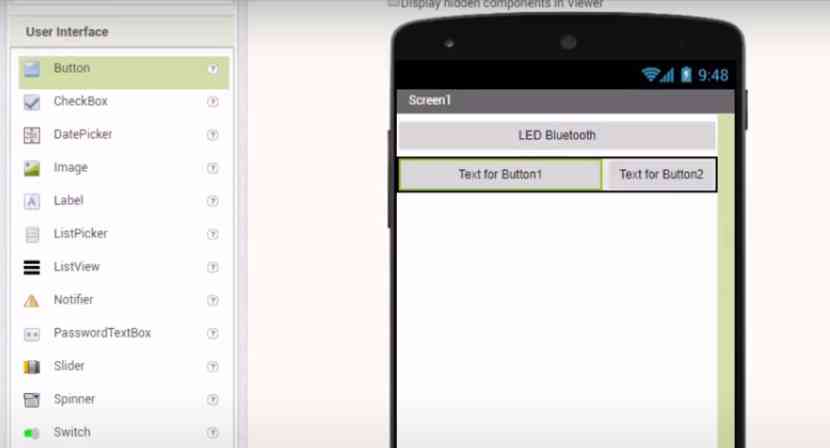
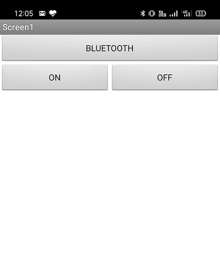
The app development on MIT app Inventor starts with picking elements from the user interface section starting with a list picker and then putting two buttons which is then followed by a bluetooth client. The size of the elements are changed according to the design we like.
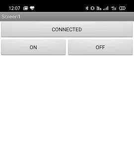
The name of the List picker is changed to BLUETOOTH which is basically a button which after clicking will change to show the availaible connections. Once it is connected to the HC 05 bluettoth module it, Bluetooth will be changed to connected.
After clicking the BLUETOOTH present on the app, it will show you the list of the connections available and once you connect it to the HC 05. It will be changed to CONNECTED. Before clicking the BLUETOOTH, the app will not do anything but there is a reuirement of the bluetooth of the phone to be open so that it can have the access of the bluetooth clients.

When button one is pressed it will send 1 to the bluetooth. The board will then interprate this according to the program given to microcontroller of the board which will take the commands from the bluetooth module .
When button two is pressed it will send 0 to the bluetooth module.
I made the program and app and ran it on arduino board and then on the board designed by me .
Code for Final Project Board
    /*This work by NEERAJ GUPTA is licensed under a Creative Commons Attribution-ShareAlike 4.0 International License.*/

  #include "SoftwareSerial.h"

SoftwareSerial mySerial(3, 4); // RX, TX
char Incoming_value = 0;

void setup()
{
  mySerial.begin(9600);
  pinMode(13, OUTPUT);
}

void loop()
{
  if(mySerial.available() > 0)
  {
    Incoming_value = mySerial.read();
    //mySerial.print(Incoming_value);
   // mySerial.print("\n");
    if(Incoming_value == '1')
      digitalWrite(13, HIGH);
    else if(Incoming_value == '0')
      digitalWrite(13, LOW);
  }
}
The code asks the board to activate the Built in LED at Digital Pin 13 if it sees any data coming to its serial port. If the value coming is 1 then it will switch on the LED and if the command is coming to the serial port is zero then it will switch off the LED. Here i have used the software serial library and have modified the code as per the pin arrangement of my board.
Processing
Processing is an open-source graphical library and integrated development environment built for the electronic arts, new media art, and visual design communities with the purpose of teaching non-programmers the fundamentals of computer programming in a visual context. Source:WIKIPEDIA
To downlaod Processing, you can visit this
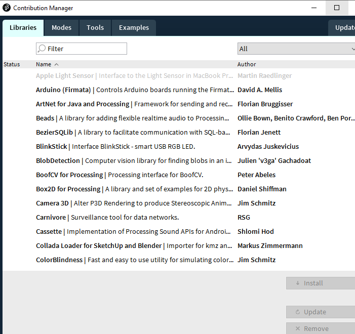
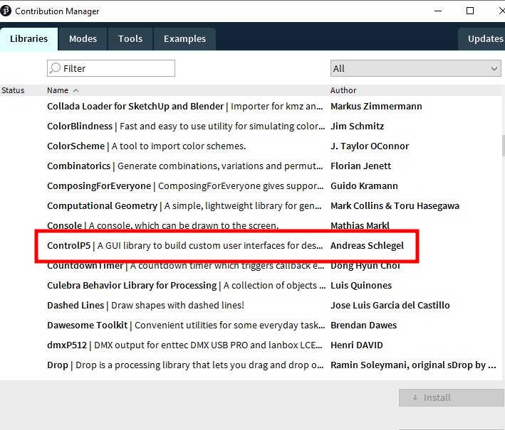
In the case of processing also you need to first import the serial library and then declare a global Serial object variable. We also have to import the Control P5 library which lets you build a graphical user interface on top of your processing sketch include Sliders, Buttons etc.
Write() lets you Write bytes, chars, ints, bytes[], Strings to the serial port
As arduino have libraries similarly it also have libraries whcih you need to install while you upload the code for various functions.
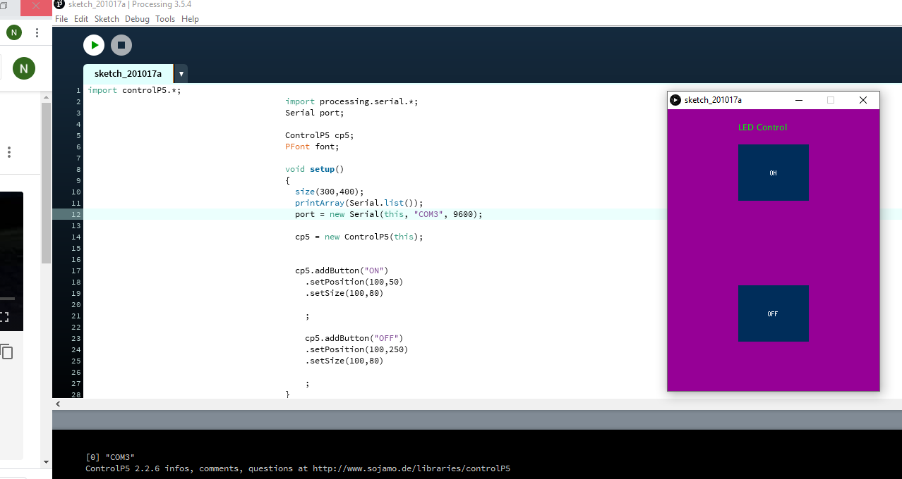
In the processing, we are going to make an interface which will control the board wgich we have made. The code is made to establish an interface. The interface which will be present on the monitor of your desktop or the screen of your laptop and from there you can give a command which will go to the board through serial communication and the board will behave the way we want it to behave accrding to the program installed in the board.
The program for processing is made to craete a screen of a certain size which is visible on the monitor and add an on and off button to it. The color of the background and the color of the buttons can be changed as per the requirement just by filling the details of the RGB required for a certain color in background(). The size of the button cal also be established by changing the values in setSize() and setPosition(100,250). We also need to tell which port we are going to use in the program itself. after creating the buttons we need to define then function we need them to do. when i press on, 1 should serially to the port and if i click off then 0 should be send serially.
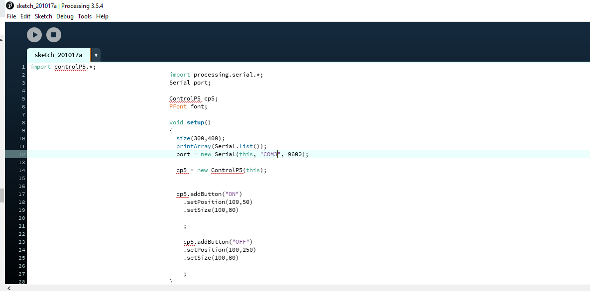
All the lines of the processing code is explained linewise below.
import controlP5.*; // import control P5 library
import processing.serial.*; // import serial library
Serial port;
ControlP5 cp5; // Control P5 object
PFont font;
void setup()
{
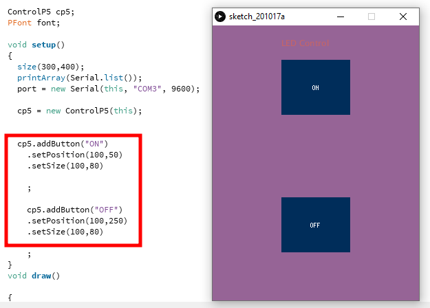
size(300,400); // windows size (width, height)
printArray(Serial.list()); // prints all availaible serial port
port = new Serial(this, "COM4", 9600); // connected the board to COM4
cp5 = new ControlP5(this);
cp5.addButton("ON") //On is the name of the button
.setPosition(100,50) // Position of the button
.setSize(100,80) // Size of the button
;
cp5.addButton("OFF") // Off is the name of the button
.setPosition(100,250) // Posotion of the button
.setSize(100,80) // size of the button
;
}
void draw() // loop
{
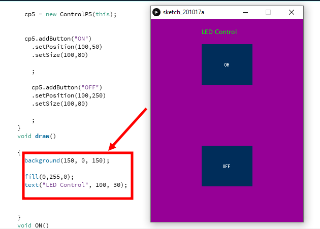
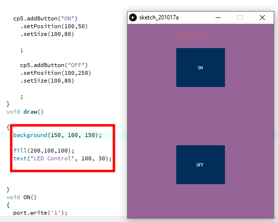
background(150, 0, 150); // Background color of the windows (r,g,b) or (0 to 255)
fill(0,255,0); // text color (r,g,b)
text("LED Control", 100, 30); // ("text", x cordinate , y cordinate)
}
// adding some functions to the buttons so that they send a charatcerr value serially
void ON()
{
port.write('1');
}
void OFF()
{
port.write('0');
}

You need to install the specicfic library whcih you are going to use in the program. The steps are similar to that for installing library for the
You can vary the values of background and fill and led control text by chanign the values of RGB
You can change the size of the buttons by chnaging the values of position and size as given in the program.
Program for the Arduino Board
      /*This work by NEERAJ GUPTA is licensed under a Creative Commons Attribution-ShareAlike 4.0 International License.*/
         void setup() {
                                          pinMode(13, OUTPUT);


                                           Serial.begin(9600); // starts serial communication at 9600 bps

                                        }

                                        void loop() {

                                          if (Serial.available()) {   // id data is availaible to read

                                            char val =  mySerial.read();

                                            Serial.println(val);

                                            if (val == '1') {   // if 1 is recieved turn the 13 pin high
                                              digitalWrite(13, HIGH);
                                              Serial.println("Led is ON");  // print Led is ON on serial monitor
                                            }

                                            if (val == '0') {  // if 0 is recieved turn the 13 pin high
                                              digitalWrite(13, LOW );
                                              Serial.println("LED is OFF");   // print Led is OFF on serial monitor
                                            }


                                          }
                                        }
The arduino code is using 13 pin as the output pin. when the value 1 is availaible on the serial port it will make the pin high and when it gets the value zero, it will make the Led off.
Program for the Designed board
         #include " SoftwareSerial.h"          //
                                         SoftwareSerial mySerial(0, 1);//rx,tx

                                        void setup() {
                                          pinMode(3, OUTPUT);


                                           mySerial.begin(9600); // starts serial communication at 9600 bps

                                        }

                                        void loop() {

                                          if (mySerial.available()) {  // id data is availaible to read

                                            char val =  mySerial.read();

                                            mySerial.println(val);

                                            if (val == '1') {  // if 1 is recieved turn the 13 pin high
                                              digitalWrite(3, HIGH);
                                              mySerial.println("Led is ON"); // print Led is ON on serial monitor
                                            }

                                            if (val == '0') {  // if 0 is recieved turn the 13 pin high
                                              digitalWrite(3, LOW );
                                              mySerial.println("LED is OFF"); // print Led is OFF on serial monitor
                                            }


                                          }
                                        }
The arduino code is using 13 pin as the output pin. when the value 1 is availaible on the serial port it will make the pin high and when it gets the value zero, it will make the Led off. Here since it is my board so i had to give different pins for serial communication and in this case i have given pin 3 and 4 for serial communication. And also imported the serial library for serial communjcation through diffeernt pins.
Program for the Final project Board
         #include "SoftwareSerial.h"
                                         SoftwareSerial mySerial(3, 4);//rx,tx

                                        void setup() {
                                          pinMode(13, OUTPUT);


                                           mySerial.begin(9600);  // starts serial communication at 9600 bps

                                        }

                                        void loop() {

                                          if (mySerial.available()) {  // id data is availaible to read

                                            char val =  mySerial.read();

                                            mySerial.println(val);

                                            if (val == '1') {   // if 1 is recieved turn the 13 pin high
                                              digitalWrite(13, HIGH);
                                              mySerial.println("Led is ON");  // print Led is ON on serial monitor
                                            }

                                            if (val == '0') {  // if 0 is recieved turn the 13 pin high
                                              digitalWrite(13, LOW );
                                              mySerial.println("LED is OFF");// print Led is OFF on serial monitor
                                            }


                                          }
                                        }
The arduino code is using 13 pin as the output pin. when the value 1 is availaible on the serial port it will make the pin high and when it gets the value zero, it will make the Led off. Here since it is my board so i had to give different pins for serial communication and in this case i have given pin 3 and 4 for serial communication. And also imported the serial library for serial communjcation through diffeernt pins.
Using processing with Final Project Board
Using Processing with Designed Board
Using Processing with arduino UNO
Experience and Conclusion
It is a great experience making apps and creating a interface to do something with the board. I have used most of the boards i can to apply to see the application of the interface. The app which i made was learnt from a tutorial and i used after understanding the code. I modified the code for the different boards which i made and controlled the boards Led with the use of the interface. We can control any other component as well after learning.