Brief Information About The Final Projects

The Vending Robot is a user friendly module derived from multiple Design and Engineering Principles. This device is capable of dispensing four solids and two liquid.This Device is designed to be a venders aid, assisting in the selling of various items both solid and liquids.
The Graphical User Interface
The machine has a lcd screen and buttons user interface where the user select products and items.
The buttons are provided to assist users scroll
DOWN and
UPthe item menu,while
MENU button allows for the selecting of items on the Vending_Machine .
The Coin Acceptor
what is the essences of having a vending machine without a section that accepts and stores specific coins. This part accepts a specific coin type so as to allows any item to be dispensed or dilivered
The Item Dispenser
For the item dispensing system helix springs will be mounted on motors to assist on item movements as shown below
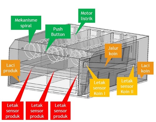
This setup allows the user to pushout the items onto a delivery slot ready for dispensing.
The Pick And Deliver Bot
This is a simple robotic setup that allows for precise item dispensing as opposed to the push and drop method synonimous to most vending machines. This mechanism elliminates the drop effect on the items making it possible to dispense all sort of items even fragle and britle items like fruits and glass items.checkout the final project for more Information
Work through a git tutorial build a personal site in the class archive describing you and your final project
Overview.
During the first week we had time to understand the structure of the course and the place where it would happen. In my case it is Kisumu and Fab Lab Winam located in Kisumu City Kenya near the Acacia hotel. Documentation is the main focus of the course. This year GitLab is being introduced to the Fab Academy students. All of us have an account on GitLab and we have to use Git in order to document our learning process. From our GitLab repository the documentation travels to a web server, where it becomes accessible to the users of the World Wide Web. I have decided (after the first week) to fill the documentation page of the first week with tutorials that could help others to set up their documentation website on GitLab. This is going to be Fab-Academy-specific and the following list is what topics we have to cover in order to get there.Git
o Installation o Configuration o Introduction• HTML
o The HTML mindset o Setting up Sublime Text o Building basic website• GitLab
o Setting up GitLab for your computer o Converting your website into Git repository o Uploading to GitLab and making it wisible on the web This would be the very basic setup that one would need for a course. This can be covered in a week if one is thorough. This is why I would stop here for the first week. Look at the second week documentation to find out next steps to make your documentation process work for you instead of the opposite.Git
I strongly suggest to use the command line version of Git. No matter how scary the command line might be, if you want to be friends with programming, begin mastering it now. Use Terminal on Mac OS X and Linux. Download Git command line for Windows or use Windows 10 Developer Mode.Installing Git
There are different ways of installing Git for each operating system. On Linux (Debian and Ubuntu) you should open Terminal and run the following command.sudo apt-get install git
It might be that sudois not the way to go and you need to change your user to
rootbefore you can install software. If so, run the following and repeat the command above.
su rootGit Configuration
Before you start working with Git, you should set it up with your persona. Three things are important. 1. Your name 2. Your email 3. Text editor Git will use your name and email to sign the so called commits which can be explained as markings in time with information about what has been changed in the project you are working on. Setting up text editor is important, as you probably do not want to spend too much time on learning something too ancient. By default the text editor is set to vim which is considered cool in the hacker community, but it takes a long time to master it. I suggest the GNU nano text editor, from my experience beginners have the least problems with it. Run the following commands in your Terminal to set Git up. git config --global user.name "David Diva".....
git config --global user.email "dave@rave.xyz"
git config --global core.editor nanoUsing Git
You will have to remember a handful of commands in order to use Git for managing versions of your project. Start with creating an empty directory for your project.Mkdir my-git-project commit c299ff48adf40a8a23c8bafbbeb6aea92923df44, these are unique commit identifiers. We can use them to roll back to a certain version in the project history. The rest should be self-explanatory.
The following is a simple workflow that you can use to version your project. I will explain more features in the GitLab part of this page.
1. Make a change (add or edit a file)
2. Use git status to see changes
3. Use git add filename to add specific file you want to commit
4. Use git commit -m 'Your commit message' to add changes to Git history
5. Repeat
Lastly you need to update the remote part (the server) with content you accumulated locally. For that you use the git push command. A screenshot below (I avoid using screenshots in this section since a lot can be done by showing plain code, but here is one real screenshot).
I also added my-git-project to my Fab Academy GitLab account.
Assignment
Model (raster, vector, 2D, 3D, render, animate, simulate, ...) a possible final project, and post it on your class page
Overview
During this week we will cover computer drawing skills and computer drawing aids . We will learning about different 3D and 3D drawing tools and environments to be used for digital fabrication. You can see the full list of tools discussed on the Fab Academy Computer-Aided Design page.
The assignment for the third week is to use one or more of these tools to design a possible final project.
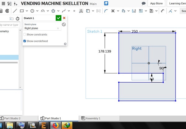
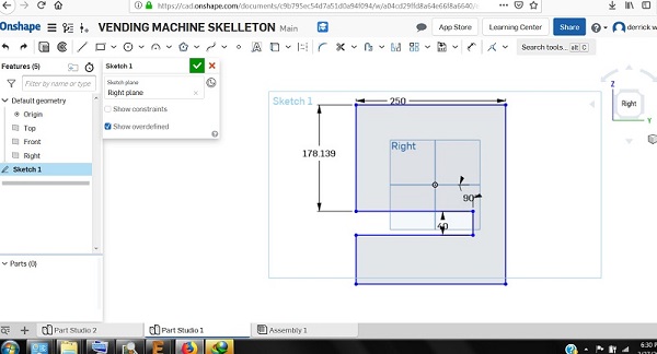
The project of mine is Vending_Machine Mashinani. I will design a structure of the Vending Vending_Machine Mashinani using a computer Aided Design tool called Onshape about Onshape see link below .
https://cad.onshape.com althought at atimes i will shift to 123d and fusio where necessary.But it is important to read through CAD environment before starting your design.
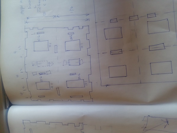
Drawing manualy on a piece of paper will direct your cad drawing develop a culture of sketching beforehand
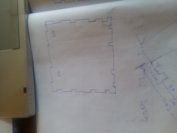
Drawing manualy on a piece of paper will direct your cad drawing develop a culture of sketching beforehand
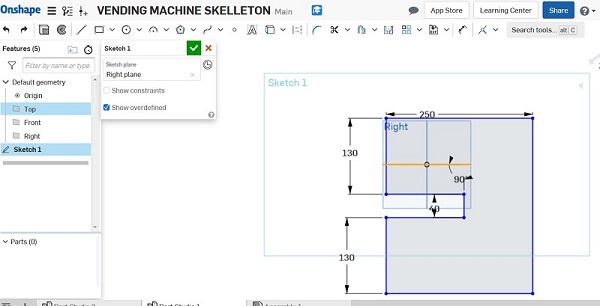
First we start with the struture partition taking keen focus on the dimensions. It is important to go through the tools sections of Onshape before starting design.This will familiarise you with this specific CAD application.
The assignment for the third week is to use one or more of these tools to design a possible final project. The project of mine is Vending_Machine Mashinani. I will design a structure of the Vending Vending_Machine Mashinani using a computer Aided Design tool called Onshape about Onshape see link below . https://cad.onshape.com
The assignment for the third week is to use one or more of these tools to design a possible final project. The project of mine is Vending_Machine Mashinani. I will design a structure of the Vending Vending_Machine Mashinani using a computer Aided Design tool called Onshape about Onshape see link below . https://cad.onshape.com
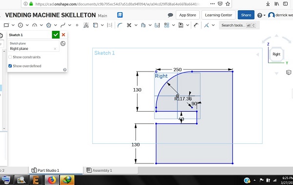
Set the curves using the insert cycle section.
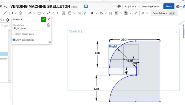
This is the side structure to be designed
.jpg)
The final structure.
3d CAD
The final structure.
.png)
for the 3d cad i went for the slider since my final project incorperates a similar mechanism.On this assingment i used 123D
.png)
The slider design is achieved by the following steps .
.png)
view topside ,insert rectangle of specified dimensions,extrude rectangle puting dimensions into considerations
.png)
for the through holes design circle on top of the rectangle and extrude appropriately.

Assignments
cut something on the vinylcutter design, lasercut, and document a parametric press-fit construction kit, accounting for the lasercutter kerf, which can be assembled in multiple ways, and for extra credit include elements that aren't flat
Overview
During the fourth week of the Fab Academy course we finally got to use some of the machines. We started out with examining the vinylcutter. The topic of the week was computer-controlled cutting. The assignment for the fourth week consisted of two parts: a group assignment and an individual one. The group assignment was about characterizing the laser cutter and for the individual one everybody had to cut anything with the vinylcutter and design, lasercut and document a press-fit contstruction kit.interesting work for me.
Vynl Cutting "IronMan Helmet"
.png)
I dont know what it is about vynl cutters and png images because all images sent for processing to the vynlcutter have to be png,personally i hate png images i think they are lame but because of this weeks asignments i am forced to use it.I know this I love comics especially marvel comics so in this weeks assignments i will vynlcut the helmet of IronMan.
.jpg)
I dont know what it is about vynl cutters and png images because all images sent for processing to the vynlcutter have to be png,personally i hate png images i think they are lame but because of this weeks asignments i am forced to use it.I know this I love comics especially marvel comics so in this weeks assignments i will vynlcut the helmet of IronMan.
Assignments
Make an in-circuit programmer by milling the PCB, program it, then optionally try other PCB processes.
Overview
Electronic Producton consisted of two parts: a group assignment and an individual one. The group assignment was about characterizing the specifications of one’s PCB production process. The individual assignment was to make in in-circuit programmer by milling a PCB and soldering components on it.
characterizing the specifications of the PCB production process.
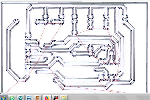
In this section i got guidelines from the fab academy tutorials.http://fabacademy.org/2019/docs/FabAcademy-Tutorials/week04_electronic_production/srm20_windows.html. If you are like me and you like learning through practicles i would suggest the fabacademy tutorials the first step is having your design as a png image the key words in this entire process is observation,and following instructions.
the fabmodule
this is an online tool that alows you to covert your image to machine tool paths http://fabmodules.org/
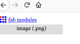
Using the fab module as i said is more of following instructions and undestanding the kind of machine you have for my case its SRM20 monofab,understanding the type of drill bit ,end mill you wil use. lets understand how fab modules work. http://fabmodules.org/
Using the fab module is pretty straight forward.this is what i managed to collect. http://fabmodules.org/
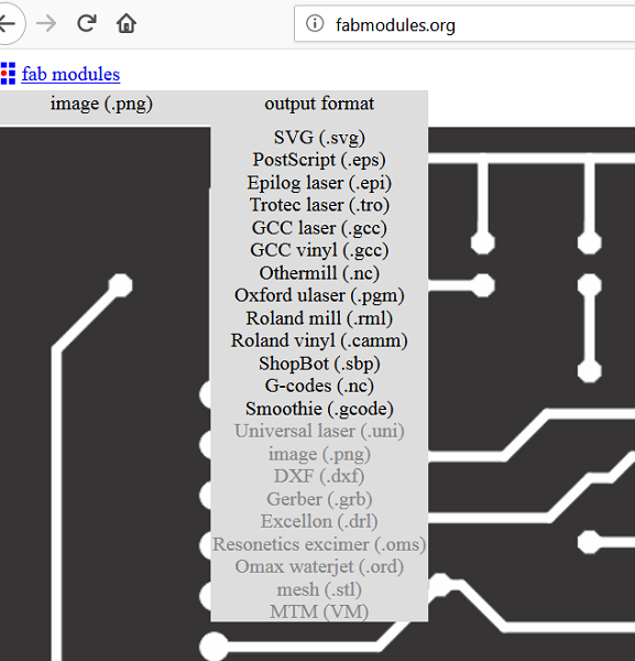
go to.http://fabmodules.org/. select input format as png

output select roland mill


output select roland mill
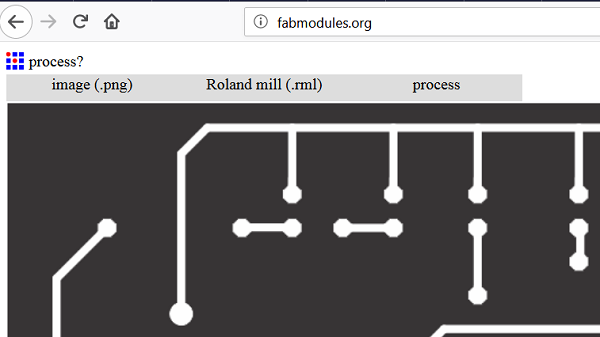
process pcb traces 1/64 an slide down appears follow instructions as directed by the tutorial.http://fabmodules.org/.
Input all variable as instructed if complete hit the calculate button for

you now have your machine tool path,save and download the

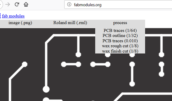
Input all variable as instructed if complete hit the calculate button for
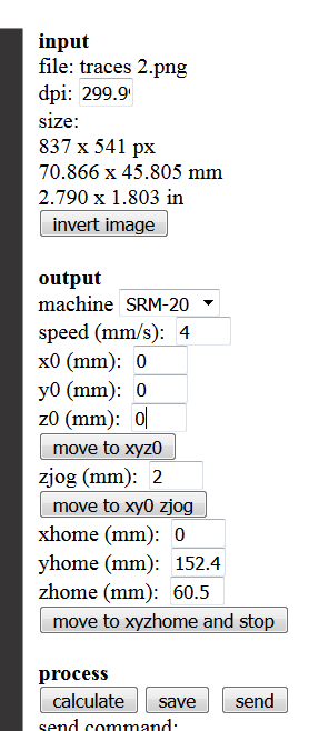
you now have your machine tool path,save and download the
Working with Roland SRM20
Turn on Roland Modela and the computer and open VPanel for SRM-20 A nice tip is to warm the spindle for 10 min at mid Rpm before using it.
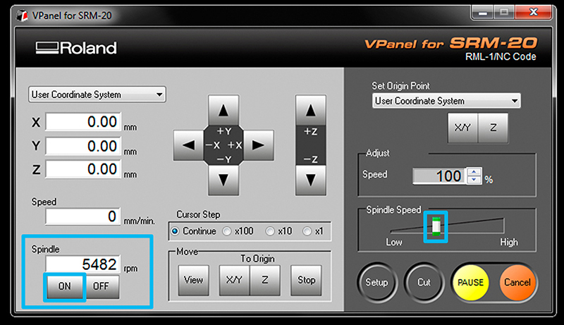
Turn on Roland Modela and the computer and open VPanel for SRM-20 A nice tip is to warm the spindle for 10 min at mid Rpm before using it.
Set the X/Y/Z zeros
As stated in the tutorials its good to start just a few milimiters inside. Move the machine to its position by using the X/Y arrows in VPanel for SRM-20 Decide where to set the origin on your board.It depends on where you taped your board. When you have choosen the position click on Set origin X/Y in Vpanel
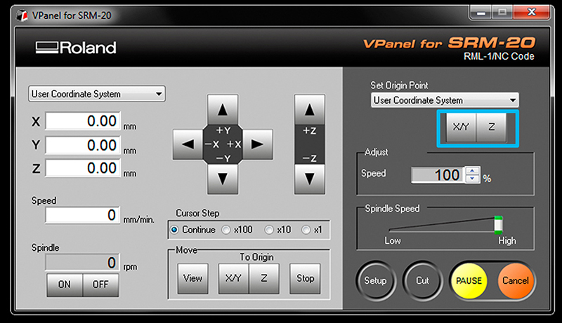
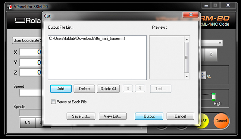
Send the traces!
Click “Cut” on the control panel. A new window will appear where you will select your traces cutting file, now click Output and the machine should start. You can send multiples files at once if you have set differents origins in fabmodules
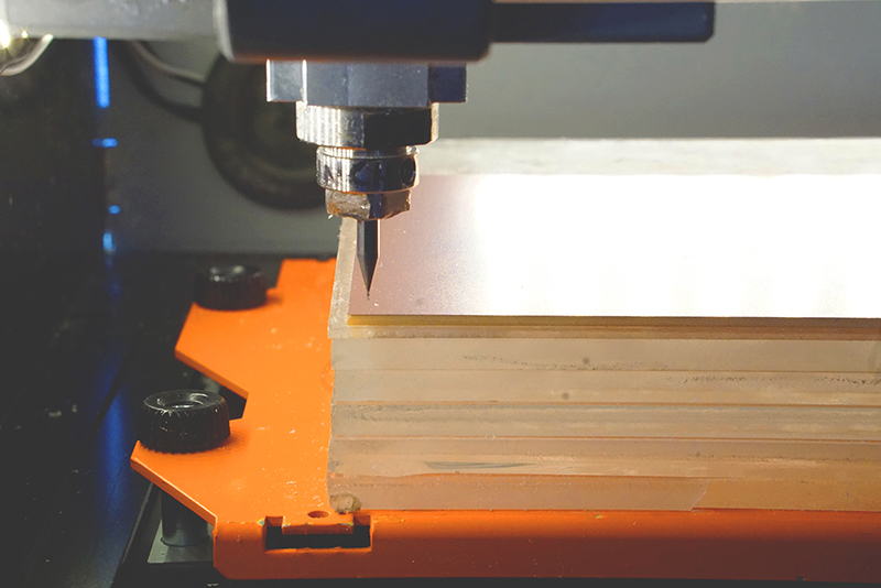
milling Outcomes
Below are some of my failed attempts
.jpg)
.jpg)
This was the final attempts for me its fair enough.
.jpg)
Send the outcut/holes!
When the machine stops, you will have to vacuum to see the traces.Do not remove the board! Now we are going to repeat the same Z origin procedurebut before we have to change the end mill to use the 1/32 end mill. After zeroing the Z (only the Z)click "CUT" again in the control panel but now choose your Outcut/Holes files and click Output. Only set the origin Z or you will not be able to match the last origin X/Y When the machine stops,remove your board with the help of a spatula,don't be Hulk or you will break the board.Vacuum away the plastic and metal chips in the area. Enjoy your PCB and Clean your mess and files after you're done working!
Assignment
- design and 3D print an object (small, few cm3, limited by printer time) that could not be made subtractively - 3D scan an object (and optionally print it)

Overview
3d print of a design object ,3d scan of an object
.jpg)
Getting started
In 3d printing its important to know the machine you are using and how to load gcode onto it.this week we explore the options and possibilities in 3d Printing This was one of the weeks when it was hard to motivate myself to complete and document as It was my first encounter with 3d Printing. 3D printing is a useful way of rapid prototyping and in relation to my final project I can use it to iterate on the housing.
123D designs and editting
3d designs is easy when you have mastered the drawing tool bar because it all about resizing extruding shaping checking Repeat.
3d designs is easy when you have mastered the drawing tool bar because it all about resizing extruding shaping checking Repeat.
3d designs is easy when you have mastered the drawing tool bar because it all about resizing extruding shaping checking Repeat.
3d designs is easy when you have mastered the drawing tool bar because it all about resizing extruding shaping checking Repeat.
3d designs is easy when you have mastered the drawing tool bar because it all about resizing extruding shaping checking Repeat.
.png)
3d designs is easy when you have mastered the drawing tool bar because it all about resizing extruding shaping checking Repeat.
.png)
3d designs is easy when you have mastered the drawing tool bar because it all about resizing extruding shaping checking Repeat.
.jpg)
3d designs is easy when you have mastered the drawing tool bar because it all about resizing extruding shaping checking Repeat.
.jpg)
3d designs is easy when you have mastered the drawing tool bar because it all about resizing extruding shaping checking Repeat.
.jpg)
3d designs is easy when you have mastered the drawing tool bar because it all about resizing extruding shaping checking Repeat.
.jpg)
3d designs is easy when you have mastered the drawing tool bar because it all about resizing extruding shaping checking Repeat.
.jpg)
3d designs is easy when you have mastered the drawing tool bar because it all about resizing extruding shaping checking Repeat.
.jpg)
3d designs is easy when you have mastered the drawing tool bar because it all about resizing extruding shaping checking Repeat.
.jpg)
3d designs is easy when you have mastered the drawing tool bar because it all about resizing extruding shaping checking Repeat.
.jpg)
3d designs is easy when you have mastered the drawing tool bar because it all about resizing extruding shaping checking Repeat.
.jpg)
3d designs is easy when you have mastered the drawing tool bar because it all about resizing extruding shaping checking Repeat.
.jpg)
3d designs is easy when you have mastered the drawing tool bar because it all about resizing extruding shaping checking Repeat.
.jpg)
3d designs is easy when you have mastered the drawing tool bar because it all about resizing extruding shaping checking Repeat.
.jpg)
3d designs is easy when you have mastered the drawing tool bar because it all about resizing extruding shaping checking Repeat.
.jpg)
3d designs is easy when you have mastered the drawing tool bar because it all about resizing extruding shaping checking Repeat.
.jpg)
3d designs is easy when you have mastered the drawing tool bar because it all about resizing extruding shaping checking Repeat.
.jpg)
3d designs is easy when you have mastered the drawing tool bar because it all about resizing extruding shaping checking Repeat.
.jpg)
3d designs is easy when you have mastered the drawing tool bar because it all about resizing extruding shaping checking Repeat.
.jpg)
3d designs is easy when you have mastered the drawing tool bar because it all about resizing extruding shaping checking Repeat.
.jpg)
3d designs is easy when you have mastered the drawing tool bar because it all about resizing extruding shaping checking Repeat.
.jpg)
3d designs is easy when you have mastered the drawing tool bar because it all about resizing extruding shaping checking Repeat.
.jpg)
3d designs is easy when you have mastered the drawing tool bar because it all about resizing extruding shaping checking Repeat.
.jpg)
3d designs is easy when you have mastered the drawing tool bar because it all about resizing extruding shaping checking Repeat.
The deal here is to place the components well spread on the board .
Once every thing is placed in position ratsnets the the route .
electronics design
Assignment
redraw the echo hello-world board, add (at least) a button and LED (with current-limiting resistor) check the design rules, make it, and test it
Overview
After programming the echo hello world board we are required to control an led via a button.
Getting started
After programming the echo hello world board we are required to control an led via a button.
Eagle designs and editting
After programming the echo hello world board we are required to control an led via a button.In elecronics design it is important to choose a CAD you are familliar with this will help fasten your work and make easy the design process.
As for me this weeks assingment should be fairly simple since in my hello world board i made provisions for input and output which is explained in the the Electronic Production week.
.jpg)
In eletronics design most of the work is in circuit layout this is an attempt using ATTINY44
.jpg)
This is usually the beginning point for those of us using eagle it is important to have a visual or mental picture of how you want your board to look like positioning and
.jpg)
The deal here is to place the components well spread on the board .
.jpg)
Once every thing is placed in position ratsnets the the route .
.jpg)
electronics design
.jpg)
it is beginning to shape up.
.jpg)
When you are done export image ready for production.
.PNG)
.PNG)
This is the same process as shown above but now its applied for ATTINY45.
.PNG)
This is the same process as shown above but now its applied for ATTINY45.
.PNG)
This is the same process as shown above but now its applied for ATTINY45.
.PNG)
This is the same process as shown above but now its applied for ATTINY45.
.PNG)
This is the same process as shown above but now its applied for ATTINY45.
.PNG)
This is the same process as shown above but now its applied for ATTINY45.
.PNG)
.png)
This is the same process as shown above but now its applied for ATTINY45.
.png)
This is the same process as shown above but now its applied for ATTINY45.
.png)
This is the same process as shown above but now its applied for ATTINY45.
.png)
This is the same process as shown above but now its applied for ATTINY45.
.png)
This is the same process as shown above but now its applied for ATTINY45.
.png)
This is the same process as shown above but now its applied for ATTINY45.
.png)
This is the same process as shown above but now its applied for ATTINY45.
.png)
This is the same process as shown above but now its applied for ATTINY45.
During the Week 08 we had to explore the possibilities of computer-controlled machining. In our case it meant gaining understanding about the terminology and available machines involved. The individual assignment was about making something big. You can find more information about the week on the Fab Academy class page of the week. Below are some notes from the lecture. Not much, but still.
RhinoCAM is the preferred software for CAM at Fab Lab BCN. In order to use it, you have to type RhinoCAM2015 in the command line of Rhino and hit ENTER. You can use DXF file format with RhinoCAM.
Make sure that you are in the MILL module.
.jpg.) The strategies that we are going to use this week are the 2 Axis strategies. One might ask why 2 axis for X, Y and Z? It is because Z is not considered as an axis in this case.
Facing or Roughing is used to flatten the top layer of the material.
The strategies that we are going to use this week are the 2 Axis strategies. One might ask why 2 axis for X, Y and Z? It is because Z is not considered as an axis in this case.
Facing or Roughing is used to flatten the top layer of the material.
.jpg.) Pocketing is for creating pockets, or pits in other words, into the material. One can create things like boxes or cups by using this strategy.
Profiling is used to follow a vector line in order to cut something. You can position the tool on one side of the line (similar to tangent contstraint in CAD).
Engraving is similar to profiling, but insdead of movig the tool on one side of the line, the center of the tool follows the line.
V-Carving relates to tools that have a V shape. It is useful for cuts that have to be in an angle. It is also useful for engraving text. Nice for creating decorative cuts that employ depth and shadow-play.
Hole Pocketing is used to create holes. It is similar to Pocketing, but does not leave material on the bottom. It cuts as deep as the defined material thicness.
Hole Profiling creates holes, but instead of using the pocketing / engraving approach, it cuts the pieces out by using their outlines. It is important to use tabs for this strategy.
Add tabs to pieces that will be cut out from the material in order to avoid excessive amounts of panic!
Pocketing is for creating pockets, or pits in other words, into the material. One can create things like boxes or cups by using this strategy.
Profiling is used to follow a vector line in order to cut something. You can position the tool on one side of the line (similar to tangent contstraint in CAD).
Engraving is similar to profiling, but insdead of movig the tool on one side of the line, the center of the tool follows the line.
V-Carving relates to tools that have a V shape. It is useful for cuts that have to be in an angle. It is also useful for engraving text. Nice for creating decorative cuts that employ depth and shadow-play.
Hole Pocketing is used to create holes. It is similar to Pocketing, but does not leave material on the bottom. It cuts as deep as the defined material thicness.
Hole Profiling creates holes, but instead of using the pocketing / engraving approach, it cuts the pieces out by using their outlines. It is important to use tabs for this strategy.
Add tabs to pieces that will be cut out from the material in order to avoid excessive amounts of panic!
.jpg.) Tabs keep the pieces to be removed in place while cutting your material. You would cut the tabs after the milling machine has finished its job. You would use a hammer and a chisel or a handsaw to do the final cuts. If there are no tabs, the piece can get loose, jump off and destroy your lab!
Click on Post to open the Post Processor Options window. ShopBot MTC post processor has to be used for the ShopBot milling machine. Mach3MM post processor has to be used for the Precix machine. Go to Fab Lab BCN Wiki to learn more.
Post File Extension has to be set to .sbp.
Tabs keep the pieces to be removed in place while cutting your material. You would cut the tabs after the milling machine has finished its job. You would use a hammer and a chisel or a handsaw to do the final cuts. If there are no tabs, the piece can get loose, jump off and destroy your lab!
Click on Post to open the Post Processor Options window. ShopBot MTC post processor has to be used for the ShopBot milling machine. Mach3MM post processor has to be used for the Precix machine. Go to Fab Lab BCN Wiki to learn more.
Post File Extension has to be set to .sbp.
.jpg.) Click on Stock to specify material that we are going to use for milling.
You can import 3D objects from other 3D software, but you have to make sure that the top surface matches the Z axis origin (value 0).
Creating the stock usually involves creating a new Box Stock instance. The origin of the Box Stock should be set the top-left corner of the box representation.
Measure your material before creating the stock instance.
Click on Stock to specify material that we are going to use for milling.
You can import 3D objects from other 3D software, but you have to make sure that the top surface matches the Z axis origin (value 0).
Creating the stock usually involves creating a new Box Stock instance. The origin of the Box Stock should be set the top-left corner of the box representation.
Measure your material before creating the stock instance.
.jpg.)
Stock from selection can be used as well. You can define your material by drawing in the 3D view. You can extrude the outline downwards in order to define the material thickness. When you are done, click on Stock and select Stock from selection.
Click on Stock visibility icon to enable a ghost image of your material. You can delete the original object, the stock ghost will be still there.
You should position the bottom-left of the material at the X0, Y0 position of the 3D view.
.jpg.)
 It is important to mark where you are going to put the screws for attaching the material to the build plate of the milling machine.
The first CNC strategy is going to be for the screw marking. Add single points to mark the places where you want to add screws. If you skip this, you have a higher possibility to break the tool as it hits the screws. You (and the machine) should know where they are.
Holes/Drill can be used to mark the skrew locations. Select the points which define the drilling locations.
It is important to mark where you are going to put the screws for attaching the material to the build plate of the milling machine.
The first CNC strategy is going to be for the screw marking. Add single points to mark the places where you want to add screws. If you skip this, you have a higher possibility to break the tool as it hits the screws. You (and the machine) should know where they are.
Holes/Drill can be used to mark the skrew locations. Select the points which define the drilling locations.
.jpg.)
 Tool selection lets you define parameters for the tool you are using.
The less flutes your tool has, the faster you have to go in terms of RPM.
Tool selection lets you define parameters for the tool you are using.
The less flutes your tool has, the faster you have to go in terms of RPM.
.jpg.)
 >
Search: ShopBot chip load. Use GUHDO chipload calculator (scroll down to the bottom of the page).
You can also use the official ShopBot chip load guide or consult the Fab Academy Barcelona CNC tips.
Clearance is the tool traveling distance above the material when rapidly changing location. It is important to set it if you use attachments that stand out above the material.
We are going to do most tasks with a 6mm tool. First steps are the following.
>
Search: ShopBot chip load. Use GUHDO chipload calculator (scroll down to the bottom of the page).
You can also use the official ShopBot chip load guide or consult the Fab Academy Barcelona CNC tips.
Clearance is the tool traveling distance above the material when rapidly changing location. It is important to set it if you use attachments that stand out above the material.
We are going to do most tasks with a 6mm tool. First steps are the following.
.jpg.)
.jpg) Put the material on the build plane of the machine.
Set the origin of the milling machine.
Use the screw marking strategy.
Put the material on the build plane of the machine.
Set the origin of the milling machine.
Use the screw marking strategy.
.jpg)
.jpg) Dogbones are additional interior corner cuts for connecting parts. Dogbones one has to define herself for interior corners of connecting parts. Since the tool of a milling machine is circular, it is not possible to create sharp interior corners otherwise.
The not recommended, but fast way of creating dogbones is to define points on a separate layer in RhinoCAM and create a drilling strategy from them.
Hit the Play button to preview the simulation of the created strategies.
Dogbones are additional interior corner cuts for connecting parts. Dogbones one has to define herself for interior corners of connecting parts. Since the tool of a milling machine is circular, it is not possible to create sharp interior corners otherwise.
The not recommended, but fast way of creating dogbones is to define points on a separate layer in RhinoCAM and create a drilling strategy from them.
Hit the Play button to preview the simulation of the created strategies.
.jpg)
.jpg.) To create a strategy, you have to select one or more paths in your design and then choose a strategy template from the Program menu. A window will open and you will have to define additional parameters.
Cut Parameters define how the tool should move along the line and in what direction it should spin. In Global Prameters you can specify such parameters as Tolerance which specifies what is the maximum distance of the interpolated line from the actual vector toolpath. Region refers to the path that we are selecting in RhinoCAM’s design.
Cut Levels you hace to specify At Top for the Location of Cut Geometry. Add 1mm more for the Total Cut Depth in order to make sure that the tool cuts through.
You can do most things with Pocketing, Engraving and Profiling.
To create a strategy, you have to select one or more paths in your design and then choose a strategy template from the Program menu. A window will open and you will have to define additional parameters.
Cut Parameters define how the tool should move along the line and in what direction it should spin. In Global Prameters you can specify such parameters as Tolerance which specifies what is the maximum distance of the interpolated line from the actual vector toolpath. Region refers to the path that we are selecting in RhinoCAM’s design.
Cut Levels you hace to specify At Top for the Location of Cut Geometry. Add 1mm more for the Total Cut Depth in order to make sure that the tool cuts through.
You can do most things with Pocketing, Engraving and Profiling.
.jpg.)
 It is good practice to create your paths using layers. Create one for marking, engraving, pocketing and profiling. That let’s you to select all paths that you want to relate to a strategy at once. The more parts you have, the more time and effort you can save with this.
The range of the Spindle Speed is from 6,000 to 14,000 RPM (rounds per minute). Feed Rate unit is millimeters per minute. 3200 mm/min is a good start for a 6mm tool with 12,000 RPM.
There are two cutting modes. Sometimes we might want to go slow at the end of a cutting strategy. Rough Depth refers to the depth we want to cut fast or rough. Finish Depth refets to the depth that we might want to cut slowly in order to reach highter cut quality. For each cutting mode we can specify depth cuts. For a 14mm rough cut we might specify 7mm depth cut step which will result in 2 cuts. For 2mm finish cut we might choose 1mm depth cut step and end up with 2 finishing cuts for the last 2mm of the material.
Rough Depth Cut should be less or equal to the diameter of the tool. For the Finish Depth Cut it should be generally less than the diameter of the tool.
Do not forget to add tabs to your profiling strategies!
It is good practice to create your paths using layers. Create one for marking, engraving, pocketing and profiling. That let’s you to select all paths that you want to relate to a strategy at once. The more parts you have, the more time and effort you can save with this.
The range of the Spindle Speed is from 6,000 to 14,000 RPM (rounds per minute). Feed Rate unit is millimeters per minute. 3200 mm/min is a good start for a 6mm tool with 12,000 RPM.
There are two cutting modes. Sometimes we might want to go slow at the end of a cutting strategy. Rough Depth refers to the depth we want to cut fast or rough. Finish Depth refets to the depth that we might want to cut slowly in order to reach highter cut quality. For each cutting mode we can specify depth cuts. For a 14mm rough cut we might specify 7mm depth cut step which will result in 2 cuts. For 2mm finish cut we might choose 1mm depth cut step and end up with 2 finishing cuts for the last 2mm of the material.
Rough Depth Cut should be less or equal to the diameter of the tool. For the Finish Depth Cut it should be generally less than the diameter of the tool.
Do not forget to add tabs to your profiling strategies!
.jpg.)
 Advanced Cut Parameters is the place where you can find
Tools Machining Options click on Regions in order to define paths that will have custom tabs. Create a new region and use the Manual Bridge Points on selection tool to add custom locations for your tabs. Then in the Control Geometry part of the strategy parameters, select the Select Predefined in order to select the predefined region with manually added tabs.
Select the strategies you want to export, right-click and select Post to generate continous machine code for the selected strategies.
Add a number in front of the strategy file to be able to tell the sequence of the strategies you want to run.
Below is a YouTube video that can help to understand most of the things discussed above.
Advanced Cut Parameters is the place where you can find
Tools Machining Options click on Regions in order to define paths that will have custom tabs. Create a new region and use the Manual Bridge Points on selection tool to add custom locations for your tabs. Then in the Control Geometry part of the strategy parameters, select the Select Predefined in order to select the predefined region with manually added tabs.
Select the strategies you want to export, right-click and select Post to generate continous machine code for the selected strategies.
Add a number in front of the strategy file to be able to tell the sequence of the strategies you want to run.
Below is a YouTube video that can help to understand most of the things discussed above.
.jpg.)
.jpg.)
.jpg.)
.jpg.)
.jpg.)
.jpg.)
.jpg.)
Assignment
Read a microcontroller data sheet program your board to do something, with as many different programming languages and programming environments as possible
Overview
This week, I programmed my "program85" hello-world board. I wrote C code and compiled it on the an arduino development board puting considerations to the pins necessary of data transfer SCK,RESET,MISO,MOSI,VCC,and GND , UPLOADED the ARDUINO ISP program on to the arduino development board that compiles the code and flashs it to the target board using ArduinoISP ports.I have experience with programmming microcontrollers expecially Atmel family Microcontrollers.This made my work easy because the microcontroller i used is from the Atmel family ATTINY45. Previous encounters with programming was on development boards and intergeted development environment.IDE for short. and my knowledge on registers, bit manipulation, and interrupts is a bit rusty, I was quite an experience learning on this weeks assignment.
Here's the list of stuff I used for this assignment: Laptop,with arduino 1.6.4 ide installed An arduino mega2560, My program85 board, and jumper wires
About Attiny45

The ATtiny25/45/85 is a low-power CMOS 8-bit microcontroller based on the AVR enhanced RISC architecture. By executing powerful instructions in a single clock cycle, the ATtiny25/45/85 achieves throughputs approaching 1 MIPS per MHz allowing the system designer to optimize power consumption versus processing speed.See picture below.
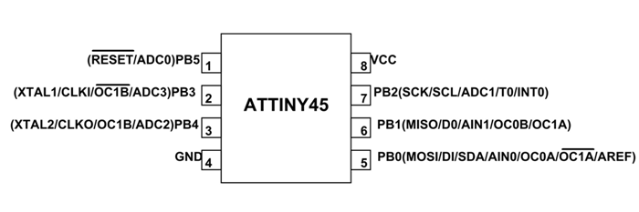
Pin Configuration
ATTINY45 is an 8 pin iC as shown in the ATtiny45 pin diagram above. All I/O pins of the chip here have more than one function. We will describe the functions of each pin below.
Pin1, PB5 (RESET/ADC0)
Pin by default is used as RESET pin. The pin active low. PB5 can only be used as I/O pin when RSTDISBL Fuse is programmed. . ADC0 (ADC Input Channel 0)
Pin2 and Pin3 ,PB3 (XTAL1/CLKI/OC1B/ADC3)
XTAL1 (Chip Clock Oscillator pin 1 ), CLKI(Clock Input from an External Clock Source ), ADC3 (ADC Input Channel 3), OC1B (Inverted-Timer/Counter1 Output Compare Match B Output).
Pin4,PB4 (GND)
Negative Terminal. Connected to ground
Pin5, PB0(MOSI/DI/SDA/AIN0/OC0A/OC1A/AREF)
MOSI (Master Output Slave Input). When controller acts as slave, the data is received by this pin. [Serial Peripheral Interface (SPI) for programming] , DI(Data Input for USI three-wire mode) , SDA (Two-wire Serial Bus Data Input/output Line) , AIN0(Analog Comparator Positive I/P) , OC0A(PWM - Timer/Counter0 Output Compare Match A Output) , OC1A (Inverted PWM - Timer/Counter1 Output Compare Match A Output) , AREF(Analog Reference Pin for ADC).
Pin6, PB1(MISO/D0/AIN1/OC0B/OC1A)
• MISO (Master Input Slave Output). When controller acts as slave, the data is sent to master by this controller through this pin. [Serial Peripheral Interface (SPI) for programming] , DO(Data Output for USI three-wire mode) , AIN1(Analog Comparator Negative I/P) , OC0B(PWM - Timer/Counter0 Output Compare Match B Output) , OC1A (Timer/Counter1 Output Compare Match A Output.)
Pin7,PB2(SCK/SCL/ADC1/T0/INT0)
, SCK (SPI Bus Serial Clock). This is the clock shared between this controller and other system for accurate data transfer. [Serial Peripheral Interface (SPI) for programming] , SCL (Two-wire Serial Bus Clock Line) , T0( Timer0 External Counter Input) , INT0(External Interrupt source0) , ADC1 (ADC Input Channel 1)
Pin8,VCC
Positive Terminal.
Arduino as an In System Programmer
setting up ARDUINO
In order to use Arduino as a ISP.you need the following procedure,First install Arduino IDE VERSION 1.6.4, run ide on you pc,go to files choose examples on examples select arduino isp,
managing arduino libraries to surport ATTINY45
In Arduino 1.6.4, you can install the ATtiny support using the built-in boards manager. Open the preferences dialog in the Arduino software. Find the “Additional Boards Manager URLs” field near the bottom of the dialog.Paste the following URL into the field (use a comma to separate it from any URLs you’ve already added): https://raw.githubusercontent.com/damellis/attiny/ide-1.6.x-boards-manager/package_damellis_attiny_index.json Click the OK button to save your updated preferences. Open the boards manager in the “Tools > Board” menu.boards-manager Click on the ATtiny entry. An install button should appear. Click the install button.The word “installed” should now appear next to the title of the ATtiny entry. Close the boards manager. You should now see an entry for ATtiny in the “Tools > Board” menu.Connecting the program85 or attiny45
You’ll need to provide 5V supply to the ATtiny and connect it to your programmer. That is, connecting MISO, MOSI, SCK, RESET, VCC, and GND of the programmer to the corresponding pins on the ATtiny. (Or, if you’re using an circuit w/ an ATtiny, simply connect the programmer to the ISP header on the board – you may also need to power the board separately.)
Configuring the ATtiny to run at 8 MHz
By default, the ATtiny’s run at 1 MHz. You can configure them to run at 8 MHz instead, which is useful for faster baud rates with the SoftwareSerial library or for faster computation in general. To do so, once you have the microcontroller connected, select “8 MHz (Internal)” from the Tools > Clock menu. (In Arduino 1.0.x, select the appropriate 8 MHz clock option from the main Tools > Board menu.) Warning: make sure you select “internal” not “external” or your microcontroller will stop working (until you connect an external clock to it). Then, run the “Burn Bootloader” command from the Tools menu. This configures the fuse bits of the microcontroller so it runs at 8 MHz. Note that the fuse bits keep their value until you explicitly change them, so you’ll only need to do this step once for each microcontroller. (Note this doesn’t actually burn a bootloader onto the board; you’ll still need to upload new programs using an external programmer.)
Connecting Arduino pin With ATTINY45 PINS GUIDE
This sketch turns the Arduino into a AVRISP using the following arduino pins: pin name:mega(1280 and 2560)
slave reset: 53
MOSI: 51
MISO: 50
SCK: 52
Put an LED (with resistor) on the following pins:
9: Heartbeat - shows the programmer is running
8: Error - Lights up if something goes wrong (use red if that makes sense)
7: Programming - In communication with the slave
23 July 2011 Randall Bohn -Address Arduino issue 509 :: Portability of ArduinoISP http://code.google.com/p/arduino/issues/detail?id=509
October 2010 by Randall Bohn - Write to EEPROM > 256 bytes - Better use of LEDs: -- Flash LED_PMODE on each flash commit -- Flash LED_PMODE while writing EEPROM (both give visual feedback of writing progress) - Light LED_ERR whenever we hit a STK_NOSYNC. Turn it off when back in sync. - Use pins_arduino.h (should also work on Arduino Mega)
October 2009 by David A. Mellis - Added support for the read signature command
February 2009 by Randall Bohn - Added support for writing to EEPROM (what took so long?) Windows users should consider WinAVR's avrdude instead of the avrdude included with Arduino software.
January 2008 by Randall Bohn - Thanks to Amplificar for helping me with the STK500 protocol - The AVRISP/STK500 (mk I) protocol is used in the arduino bootloader - The SPI functions herein were developed for the AVR910_ARD programmer - More information at http://code.google.com/p/mega-isp
the hello world code
int led0=0;
int led1=1;
int led2=2;
int led3=3;
// These constants won't change:
const int analogPin = A0;    // pin that the sensor is attached to
const int threshold = 400;   // an arbitrary threshold level that's in the range of the analog input


void setup() {
// initialize digital pin 13 as an output.
pinMode(led0, OUTPUT);pinMode(led1, OUTPUT);pinMode(led2, OUTPUT);pinMode(led3, OUTPUT);
}

void loop() {
// put your main code here, to run repeatedly:
int analogValue = analogRead(analogPin);

// if the analog value is high enough, turn on the LED:
if (analogValue > threshold) {
chaser();
}
else {
ledPin();
}
}

void chaser
() {
digitalWrite(led0, HIGH);   // turn the LED on (HIGH is the voltage level)
delay(100);
digitalWrite(led1, HIGH);   // turn the LED on (HIGH is the voltage level)
delay(100);
digitalWrite(led2, HIGH);   // turn the LED on (HIGH is the voltage level)
delay(100);
digitalWrite(led3, HIGH);   // turn the LED on (HIGH is the voltage level)
delay(100);              // wait for a second
digitalWrite(led0, LOW);    // turn the LED off by making the voltage LOW
delay(100);              // wait for a second
digitalWrite(led1, LOW);    // turn the LED off by making the voltage LOW
delay(100);              // wait for a second
digitalWrite(led2, LOW);    // turn the LED off by making the voltage LOW
delay(100);              // wait for a second
digitalWrite(led3, LOW);    // turn the LED off by making the voltage LOW
delay(100);              // wait for a second

}

void  ledPin() {
digitalWrite(led0, LOW);    // turn the LED off by making the voltage LOW
delay(100);              // wait for a second
digitalWrite(led1, LOW);    // turn the LED off by making the voltage LOW
delay(100);              // wait for a second
digitalWrite(led2, LOW);    // turn the LED off by making the voltage LOW
delay(100);              // wait for a second
digitalWrite(led3, LOW);    // turn the LED off by making the voltage LOW
delay(100);              // wait for a second

}
Assignment
Design a mold around the stock and tooling that you'll be using, mill it (rough cut + (at least) three-axis finish cut), and use it to cast parts
Overview
From my understanding of molding and casting i know that for one to mold the requirements are a machined or 3d printed mold and a material used for the two part casting.In two part casting one is required to cast twice. First its in the casting the primary mold which in turn will produce the final mold.therefore this section I will take us through the various stages.I will mold and cast my favorite comic logo the avengers endgame logo.
The Mold
.png)
For this part i need autodesk fusion for designing the mold ready for the machinable wax.I got alot of help from my friend Abner Otieno using ,configuring and producing the set mold.even the fusion version i used to produce the mold was primarily suggested by him.thanks Abner.
.png)
From my understanding of molding and casting i know that for one to mold the requirements are a machined or 3d printed mold and a mateiral used for the two part casting.In two part casting one is required to cast twice. First its in the casting the primary mold which in turn will produce the final mold.therefore this section I will take us through the various stages.
.jpg)
From my understanding of molding and casting i know that for one to mold the requirements are a machined or 3d printed mold and a mateiral used for the two part casting.In two part casting one is required to cast twice. First its in the casting the primary mold which in turn will produce the final mold.therefore this section I will take us through the various stages.
Assignment
Measure something: add a sensor to a microcontroller board that you have designed and read it
.jpg)
Overview
This week is for exploring sensors and enhancing our boards to be able to process sensor input and preferably to send it to a computer for further processing. My final project has a 3-button push-button on board, thus for this week I would like to explore something related to that.
What I want to do
Integrate the a button switch into my Hello Board design.execute a program write in Cpp send data on which button is pressed via serial connection. Adjust my set fuctions to react to the buttons in a specific way.my function is driving a stepper motor Let’s start with designing the circuit.
.jpg)
Designing the Circuit
I decided to start with the existing Hello Board design that I did in Eagle. After the Electronics Design week it still worked during the Embedded Programming week, thus I thought it is a good idea to build on top of it. I had to decide whether to integrate a connector to the button or build them all inclusive. I disconnected the push-button and was left with 5 free digital pins of the ATTiny.which i used four of them to connect a stepper motor.
The Program
As you all know i like using arduino IDE to design most of my projects because of its globe support and most codes are easy to find.As i was browsing online i came across this code that could run a unipolar stepper motor, change directions and even vary its speeds .What i will do is adjust a the code to only include one run and one reverse run then stop.This function is called the retriver
/*
input week
*/

// These constants won't change:
const int analogPin = A0;    // pin that the sensor is attached to
const int ledPin = 13;       // pin that the LED is attached to
const int th0 = 400;   // an arbitrary threshold level that's in the range of the analog input
const int th1 = 400;   // an arbitrary threshold level that's in the range of the analog input
const int th2 = 400;   // an arbitrary threshold level that's in the range of the analog input
const int th3 = 400;   // an arbitrary threshold level that's in the range of the analog input
const int th4 = 400;   // an arbitrary threshold level that's in the range of the analog input
const int th5 = 400;   // an arbitrary threshold level that's in the range of the analog input
const int t0 = 500;
const int t1 = t0+400;
const int t2 = t1+400;
const int t3 = t2+400;
const int t4 = t3+400;
const int t5 = t4+400;
void setup() {
// initialize the LED pin as an output:
pinMode(ledPin, OUTPUT);
// initialize serial communications:
Serial.begin(9600);
}

void loop() {
button0();button1();button2();button3();button4();button5();
}

void button0() {
// read the value of the potentiometer:
int analogValue = analogRead(analogPin);

// if the analog value is high enough, turn on the LED:
if (analogValue > th0) {
digitalWrite(ledPin, HIGH);delay(t0); digitalWrite(ledPin, LOW);delay(t0);
}
else {
digitalWrite(ledPin, LOW);
}

// print the analog value:
Serial.println(analogValue);
delay(1);        // delay in between reads for stability
}


void button1() {
// read the value of the potentiometer:
int analogValue = analogRead(analogPin);

// if the analog value is high enough, turn on the LED:
if (analogValue > th1) {
digitalWrite(ledPin, HIGH);delay(t1); digitalWrite(ledPin, LOW);delay(t1);
}
else {
digitalWrite(ledPin, LOW);
}

// print the analog value:
Serial.println(analogValue);
delay(1);        // delay in between reads for stability
}

void button2() {
// read the value of the potentiometer:
int analogValue = analogRead(analogPin);

// if the analog value is high enough, turn on the LED:
if (analogValue > th2) {
digitalWrite(ledPin, HIGH);delay(t2); digitalWrite(ledPin, LOW);delay(t2);
}
else {
digitalWrite(ledPin, LOW);
}

// print the analog value:
Serial.println(analogValue);
delay(1);        // delay in between reads for stability
}

void button3() {
// read the value of the potentiometer:
int analogValue = analogRead(analogPin);

// if the analog value is high enough, turn on the LED:
if (analogValue > th3) {
digitalWrite(ledPin, HIGH);delay(t3); digitalWrite(ledPin, LOW);delay(t3);
}
else {
digitalWrite(ledPin, LOW);
}

// print the analog value:
Serial.println(analogValue);
delay(1);        // delay in between reads for stability
}

void button4() {
// read the value of the potentiometer:
int analogValue = analogRead(analogPin);

// if the analog value is high enough, turn on the LED:
if (analogValue > th4) {
digitalWrite(ledPin, HIGH);delay(t4); digitalWrite(ledPin, LOW);delay(t4);
}
else {
digitalWrite(ledPin, LOW);
}

// print the analog value:
Serial.println(analogValue);
delay(1);        // delay in between reads for stability
}


void button5() {
// read the value of the potentiometer:
int analogValue = analogRead(analogPin);

// if the analog value is high enough, turn on the LED:
if (analogValue > th5) {
digitalWrite(ledPin, HIGH);delay(t5); digitalWrite(ledPin, LOW);delay(t5);
}
else {
digitalWrite(ledPin, LOW);
}

// print the analog value:
Serial.println(analogValue);
delay(1);        // delay in between reads for stability
}

}
Assignment
Measure something: add a sensor to a microcontroller board that you have designed and read it
Overview
This week is for exploring sensors and enhancing our boards to be able to process sensor input and preferably to send it to a computer for further processing. My final project has a 3-button push-button on board, thus for this week I would like to explore something related to that.
What I want to do
Integrate the a button switch into my Hello Board design.execute a program write in Cpp send data on which button is pressed via serial connection. Adjust my set fuctions to react to the buttons in a specific way.my function is driving a stepper motor Let’s start with designing the circuit.
Designing the Circuit
I decided to start with the existing Hello Board design that I did in Eagle. After the Electronics Design week it still worked during the Embedded Programming week, thus I thought it is a good idea to build on top of it. I had to decide whether to integrate a connector to the button or build them all inclusive. I disconnected the push-button and was left with 5 free digital pins of the ATTiny.which i used four of them to connect a stepper motor.
The Program
As you all know i like using arduino IDE to design most of my projects because of its globe support and most codes are easy to find.As i was browsing online i came across this code that could run a unipolar stepper motor, change directions and even vary its speeds .What i will do is adjust a the code to only include one run and one reverse run then stop.This function is called the retriver
/* Stepper Motor Demonstration 1 Stepper-Demo1.ino Demonstrates 28BYJ-48 Unipolar Stepper with ULN2003 Driver Uses Arduino Stepper Library DroneBot Workshop 2018 https://dronebotworkshop.com edited by Derrick Were by including ccw and cw fuctions. */ //Include the Arduino Stepper Library #include// Define Constants // Number of steps per internal motor revolution const float STEPS_PER_REV = 32; // Amount of Gear Reduction const float GEAR_RED = 64; // Number of steps per geared output rotation const float STEPS_PER_OUT_REV = STEPS_PER_REV * GEAR_RED; // Define Variables // Number of Steps Required int StepsRequired; // Create Instance of Stepper Class // Specify Pins used for motor coils // The pins used are 8,9,10,11 // Connected to ULN2003 Motor Driver In1, In2, In3, In4 // Pins entered in sequence 1-3-2-4 for proper step sequencing Stepper steppermotor(STEPS_PER_REV, 8, 10, 9, 11); void setup() { // Nothing (Stepper Library sets pins as outputs) } void loop() { cw(); delay(100); ccw(); delay(100); } void cw() { // Rotate CW 1/2 turn slowly StepsRequired = 110*STEPS_PER_OUT_REV / 32; steppermotor.setSpeed(950); steppermotor.step(StepsRequired); } void ccw() { // Rotate CCW 1/2 turn quickly StepsRequired = - 110*STEPS_PER_OUT_REV / 32; steppermotor.setSpeed(950); steppermotor.step(StepsRequired); } }
.jpg)
Overview
This week we do things related to interface and application programming. Since my final project has a part where that is needed, to finish this week I will build it, which is a graphical user interface for the vending machine. I am going to build on top of my solution from the last (input Devices) week where I created a button shield for minimal projection mapping capabilities on the fly. The idea is that one can do item collection and selection with minimal adjustments with the joystick device and do full project setup by using the web-interface. To get a better sense of what kind of projection mapping I am talking about, below you can see a video to see how my projection mapping workshops look like. I am building open source projection mapping software ofxPiMapper that runs on the Raspberry Pi minicomputers and as my final project I want to integrate that into a little box that one could use for projection mapping installations. The box would have a physical interface and also a web-based interface, which would become accessible once a computer gets connected to the WiFi network a Raspberry Pi creates around it. The WiFi connection and web interface becomes useful in scenarios when the device is connected to a projector that has no human access. On the low level there is a C++ application running on the ATMEGA328PU that takes care of the . A WiFi access point daemon has to run in parallel to open a WiFi network arount the device. Web server is being launched to host the web-interface. The web interface would forward user interface events to the projection mapping application.
What I want to do
Integrate the a button switch into my Hello Board design.execute a program write in Cpp send data on which button is pressed via serial connection. Adjust my set fuctions to react to the buttons in a specific way.my function is driving a stepper motor Let’s start with designing the circuit.
Designing the Circuit
I decided to start with the existing Hello Board design that I did in Eagle. After the Electronics Design week it still worked during the Embedded Programming week, thus I thought it is a good idea to build on top of it. I had to decide whether to integrate a connector to the button or build them all inclusive. I disconnected the push-button and was left with 5 free digital pins of the ATTiny.which i used four of them to connect a stepper motor.
The Program
As you all know i like using arduino IDE to design most of my projects because of its globe support and most codes are easy to find.As i was browsing online i came across this code that could run a unipolar stepper motor, change directions and even vary its speeds .What i will do is adjust a the code to only include one run and one reverse run then stop.This function is called the retriver
}
Assignment
Measure something: add a sensor to a microcontroller board that you have designed and read it
Overview
V-USB is a nice way to configure almost any chip into an USB1 device. Compouter Networks, the book, seems like a nice read. WireShark can be used for listening to a network.
What I want to do
Integrate the a button switch into my Hello Board design.execute a program write in Cpp send data on which button is pressed via serial connection. Adjust my set fuctions to react to the buttons in a specific way.my function is driving a stepper motor Let’s start with designing the circuit.
Designing the Circuit
I decided to start with the existing Hello Board design that I did in Eagle. After the Electronics Design week it still worked during the Embedded Programming week, thus I thought it is a good idea to build on top of it. I had to decide whether to integrate a connector to the button or build them all inclusive. I disconnected the push-button and was left with 5 free digital pins of the ATTiny.which i used four of them to connect a stepper motor.
The Program
As you all know i like using arduino IDE to design most of my projects because of its globe support and most codes are easy to find.As i was browsing online i came across this code that could run a unipolar stepper motor, change directions and even vary its speeds .What i will do is adjust a the code to only include one run and one reverse run then stop.This function is called the retriver
}
Assignment
Measure something: add a sensor to a microcontroller board that you have designed and read it
Overview
This week is for exploring sensors and enhancing our boards to be able to process sensor input and preferably to send it to a computer for further processing. My final project has a 3-button push-button on board, thus for this week I would like to explore something related to that.
What I want to do
Integrate the a button switch into my Hello Board design.execute a program write in Cpp send data on which button is pressed via serial connection. Adjust my set fuctions to react to the buttons in a specific way.my function is driving a stepper motor Let’s start with designing the circuit.
Designing the Circuit
I decided to start with the existing Hello Board design that I did in Eagle. After the Electronics Design week it still worked during the Embedded Programming week, thus I thought it is a good idea to build on top of it. I had to decide whether to integrate a connector to the button or build them all inclusive. I disconnected the push-button and was left with 5 free digital pins of the ATTiny.which i used four of them to connect a stepper motor.
The Program
As you all know i like using arduino IDE to design most of my projects because of its globe support and most codes are easy to find.As i was browsing online i came across this code that could run a unipolar stepper motor, change directions and even vary its speeds .What i will do is adjust a the code to only include one run and one reverse run then stop.This function is called the retriver
}
.jpg)
Assignment
This week assignment was to Design a machine (mechanism + actuation + automation) build the mechanical parts and operate it manually. Actuate and automate your machine. Document the group project and your individual contribution.
.jpg)
Overview
We desided to build a conveying belt with item counter Objective Count specific amount of item by moving them to a specific collection point, if count achieved stop conveyor
Individual Contribution
As stated in Mechanical Design week page, I was taking care of the group embedded systems and the overal code of the system. Also this week I did adjustments and improvements to it. I was contributing with various smaller things related to machine building and electronics, but nothing speciffic. Ideation on design improvements of the movement and sensing bit, but at the end we could make it work with the initial design.
.jpg)
The Process
While Bramuel was trying to design the structure, I was playing around with the conyeyor code . get the code here. Apart from that I was iterating on the group documentation page, adding content, adjusting things, making videos to show up.
.jpg)
The Program
As you all know i like using arduino IDE to design most of my projects because of its Global support and most codes are easy to find.As i was browsing online i came across this code that could run a dc motor, change directions and even vary its speeds .What i will do is adjust a the code to only include one run and in the event of the number of count is less than ten and stop if the count reaches ten.This function is called the conveyor

Start by declaring the variables globally

Assign the pins as pin modes at the set up section.

As you all know i like using arduino IDE to design most of my projects because of its Global support and most codes are easy to find.As i was browsing online i came across this code that could run a dc motor, change directions and even vary its speeds .What i will do is adjust a the code to only include one run and in the event of the number of count is less than ten and stop if the count reaches ten.This function is called the conveyor
// set pin numbers:
const int buttonPin = 2;     // the number of the pushbutton pin
const int motor =  13;      // the number of the LED pin
const int led =  8;
const int sensor = A0;

// variables will change:
int buttonState = 0;         // variable for reading the pushbutton status
int sensorState = 0;
int threshold = 120;

void setup() {
// initialize the LED pin as an output:
pinMode(motor, OUTPUT);
pinMode(led, OUTPUT);
pinMode(sensor, INPUT);
// initialize the pushbutton pin as an input:
pinMode(buttonPin, INPUT);
}

void loop() {
// read the state of the pushbutton value:
buttonState = digitalRead(buttonPin);

// check if the pushbutton is pressed.
// if it is, the buttonState is HIGH:
if (buttonState == HIGH) {
digitalWrite(motor, HIGH);
int i = 0;
while (i < 10){
sensorState = analogRead(sensor);
if (sensorState > threshold){
digitalWrite(led, HIGH);
delay (2000);
digitalWrite(led, LOW);
i++;
}
}
}
else {
// turn LED off:
digitalWrite(motor, LOW);
}
}
Assignment
Measure something: add a sensor to a microcontroller board that you have designed and read it
Overview
This week is for exploring sensors and enhancing our boards to be able to process sensor input and preferably to send it to a computer for further processing. My final project has a 3-button push-button on board, thus for this week I would like to explore something related to that.
What I want to do
Integrate the a button switch into my Hello Board design.execute a program write in Cpp send data on which button is pressed via serial connection. Adjust my set fuctions to react to the buttons in a specific way.my function is driving a stepper motor Let’s start with designing the circuit.
Designing the Circuit
I decided to start with the existing Hello Board design that I did in Eagle. After the Electronics Design week it still worked during the Embedded Programming week, thus I thought it is a good idea to build on top of it. I had to decide whether to integrate a connector to the button or build them all inclusive. I disconnected the push-button and was left with 5 free digital pins of the ATTiny.which i used four of them to connect a stepper motor.
The Program
As you all know i like using arduino IDE to design most of my projects because of its globe support and most codes are easy to find.As i was browsing online i came across this code that could run a unipolar stepper motor, change directions and even vary its speeds .What i will do is adjust a the code to only include one run and one reverse run then stop.This function is called the retriver
}
Assignment
Propose a final project masterpiece that integrates the range of units covered, answering:
Overview
As my final project I am building a prototype vending machine with a lcd screen and a joystick-like button device that dispenses four solids and two liquids.
What will it do?
With Vending_Machinani you will be able to purchase items by simply inserting coins on the coin detection device and by the help of an item dispenser and liqid dispenser get your desireble taste...
Who’s done what beforehand?
vending machines are everywhere and the mode of implimentation varied but the one that captured my eyes was the one by HOW TO MECHARONICS al share a link below
What will you design?
Electronics. I will design a PCB as a addon board for the motor and soleniod driving mechanisms. The board will interpret button signals coming from a 3 button and drive motors to dispense item to the user. Housing. I will design a case that feels nice in one’s hand and makes Vending_Machinani easy to use. I plan to use Fusion 360 for the design part. I will iterate on the digital fabrication part by using Formlabs Form 2 3D printer. Later I would like to use injection molding to create professionally looking housing and try to sell a limited amount of test devices. Software. I plan to modify my ofxPiMaper software to accept signals from the 5-way joystick button and the web interface. The web interface is a completely fresh piece of software that I have to develop, you can read about the first part of my efforts on the interface programming week page. Configuration. The ATMEGA328PU has to be configured to spawn a WiFi access point one can connect to with a computer or mobile device. Once connected, the web interface would be accessible through a web browser. I will make a simple product website available at umap.io as well.
What materials and components will be used?
To make the uMap PCB I will use a double-sided FR4 board (5cm x 8cm and 2mm thick). Once milled, I will lay out the following components. 1K resistors for the LED’s 10K resistors for other connections SparkFun COM-10063 5-Way switch for input ATTiny44 microcontroller N-MOSFET transistors for shifting levels between 5V and 3.3V Headers for connections to the Raspberry Pi and ISP programmer LED’s for power status and debugging Vias to connect top and bottom sides of the PCB four dc motors ATMEGA328PU microcontroller two steppermotors Spacers relay block 16BY2 LCD screeen. For the 3D printing iterations of the housing I will use the FormLabs Clear resin. I would like to try the FormLabs Tough resin if it will be available at the lab. If I will get that far, I will try to make aluminium molds for injection molding with the Precious Plastic injection molding machines available at the lab. For that I would use recycled plastic. And I will need a Raspberry Pi Zero W with an 8GB SD card for each unit.
Where the parts will come from?
Most of the electronics can be ordered from DigiKey. The SparkFun 5-way switch is available from SparkFun directly or Mouser Electronics. In order to iterate on the enclosure, I will use the FormLabs Clear resin available from FormLabs directly. For injection molding I would use recycled plastic available around me. The ATMEGA328PU one can get from many sources and it can happen that the shop is limiting the amount of possible purchases. I intend to buy from pi-shop.ch or pimoroni.de. An alternative due limited Raspberry Pi availability would be to use the Banana Pi Zero that shares the size characteristics with Raspberry Pi Zero W. It would possibly cause problems with the software, but I want to try it out in one of my future development iterations.
How much will they cost?
The most problematic part to get is the ATMEGA328PU. In order to get it from Mouser Electronics one has to wait for more than 2 weeks. I bought 2 pieces and paid 1000 kenyan shilings. I made a spreadsheet (available in the Files section) and the bill of materials or Vending_Machine resulted in 10000 kenyan shilings.
What parts and systems will be made?
As stated above, a custom PCB will be milled with the Roland SRM-20 CNC machine. A CNC cut structure will be 3D designed with the FormLabs Form 2 3D printer. I will use the ShopBot later to create the aluminium mold for injection molding with Precious Plastic injectors. On the software level my open source projection mapping software ofxPiMapper will be modified and upgraded to work with the PCB solution and the web interface. The web interface will be developed by using the three.js 3D graphics library for web browsers. Raspbian Lite Linux distribution will be upgraded with various packages so the Raspberry Pi Zero W would spawn a WiFi network to make the web interface available to users. A simple product website umap.io will be developed to celebrate a successful execution of the Fab Academy final project.
What processes will be used?
For the electronics part Autodesk Eagle software will be used to design the schematics and lay out the PCB. On the lab level for rapid design iterations Photoshop and Mods will be used to create machine code for the Roland SRM-20 CNC milling machine. Since the double-sided PCB, I will use a manual via crimper (a machine with the brand / name BUNGARO is available at the lab) to place 0.5mm thick vias into the 2mm thick double-sided copper clad. I will use Autodesk Fusion 360 design software to design parts for 3D printing, molds for injection molding and documentation later. Formlabs Form 2 SLA 3D printer will be used for rapid prototyping and iterating on the housing. I might use some more milling and / or molding and casting to produce soft parts for the final product. The 5-way switch could be covered with a soft cap made from silicone or rubber.
What questions need to be answered?
There are a number of questions that can not answer after developing the first working prototype. One thing that I will know after making it, that it works. Can it be made cheaper is another question. After calculating costs for the parts, I could see that many parts could be avoided by simplifying the design. Ideas about simplification also arise from the experience gathered while building the prototype. How hard or easy it is to create a injection mold for it? I have heard many opinions. Some say it is not too hard, others that it would be in the range from 1000 EUR to 2000 EUR. Tolerances are hard to manage. Companies who do that are not too friendly in terms of collaboration and creating the design together. I will have to find out the best practical and conceptual way in terms of injection molding the case. Is Raspberry Pi Zero W the best choice or Banana Pi Zero could be better? I have not tested the software on the Banana Pi. Theoretically, if it works there, Banana Pi Zero looks like a candidate otherwise. Will there be users and will they love it? I can use the website in order to find out. Releasing a preview video of the product and asking visitors for feedback could be a way. If things go well, I would try to launch a Kickstarted campaign to make a batch of 100 units for starters.
How will it be evaluated?
Depends on who is evaluating. As for me, it will take a year to test its durability and how well it plays with the type of projects it is intended for. User feedback will be an important way to evaluate its performance. If the users will buy it and / or contribute to the codebase, it will be a good sign. For the first prototype, it should be usable for projection mapping, it should look good and feel good in one’s hand. It should generate good feedback from most of the people I show and demontstrate it to.
Conclusions
There are parts where I could use more parts that are produced by using machines at the lab. Spacers would be one of the things where I could use lasercutter or casting and molding. The same goes for the soft pad for the 5-way button. I could also add another sensor to the board to make it a bit fancier although I feel rather sceptical towards this idea. My personal goal is to keep it rather minimal, but interesting enough to make it fun to play with. I would like it to be cheap to produce as well.
Assignment
Develop a plan for dissemination of your final project prepare drafts of your summary slide (presentation.png, 1920x1080) and video clip (presentation.mp4, 1080p HTML5, < ~minute, < ~10 MB) and put them in your root directory
Final Project Slides
In this section I will describe what steps I will take during and after the course to spread the information about my project (or product) and what would be its possible future. Below you can see my final project presentation slide. I kept it all black and white to emphasize the minimal aspect of the project. Grids and details stand for the underlying complexity and professional use of it.
Dissemination
The main tool for disseminating information of the project will be its website. I bought the domain umap.io and connected it with my web server. I believe in websites as presentation tools. A website remains available and visible even without you being at a specific location. It is crawlable and thus can be found on the internet by using one of the search engines. I plan to have a development blog on the website where I will describe the further development of the project. The Fab Academy documentation goes this far, but there are still some iterations ahead before I could launch uMap as a product. I want uMap to be open source software and hardware. I want to publish the designs online and make it possible for the people to be able to print and produce it themselves or at least be able to fix problems themselves if they occur.
Crowdfunding
Once I get a solid working prototype, I want to make a crowdfunding campaign to fund the production of, say, 100 units. According to my recent calculations, the money to be gathered could be in the range between 5,000 and 10,000 EUR. If the material expenses for 20 units is 820 EUR, for 100 of them it would be 4100. I have to add shipping expenses, injection molding services, PCB manufacturing as well as legal expenses to the list. Would be also nice to get paid for one month of work on top of that also. Thus 10,000 EUR seems like a realistic estimate for the goal of the first uMap crowdfunding campaign. Crowdfunding platforms such as Kickstarter or Indiegogo would be used for the campaign. Most probably I will do it from Germany and Kickstarter is well supported there since it is OK to register as a freelancer with a valid German bank account. Things to consider regarding a campaign is a precise estimation of expenses. As mentioned above, material expenses are not the only ones. There are services that I will have to purchase on top to make it happen. One of the most important things for a campaign is a good video. I will need someone with professional sound design and camera skills. I could do editing myself, but it may be better if I have someone to do it. These expenses would be added to the crowdbunding campaign goal. The so called rewards have to be figured out for different values of pledges. This could be as traditional as a sticker and device itself (or a batch) or something original as having a prototyping session together, having a hackathon on a beach, the list can go on here.
Licensing
Since I want the vending machine to be open source, I have to think about licensing of the software and hardware parts. For the software part I still can not decide between MIT and GNU GPL licenses. Both of them are good. I use the MIT license for my open source projection mapping software ofxPiMapper as the host platform openFrameworks uses it. The main points of the MIT license are: Everyone can use the code for free It does not matter if the derrivative is proprietary One should refer to the original license / author in case the resulting software is being used and redistributed The GNU General Public License is a bit more restrictive than the MIT license. In general it permits anybody to use, study and re-distribute the source of the software. One can sell the derrivative software at any price, but the source should remain open and the same GPL license terms should be applied. GPL licensed software are not compatible with Non-Disclosure-Agreements or illumitati deals. The main difference is that software licensed under the terms of GNU GPL should never be proprietary, which I prefer conceptually. For the hardware part the licensing is a bit different. As explained in the Open Source Hardware Wikipedia page, open source hardware rely more heavily on patent rather than on copyright law. Open source hardware is hardware whose design is made publicly available so that anyone can study, modify, distribute, make, and sell the design or hardware based on that design. From the list of open source hardware licenses, the ones I would like to choose most likely are the CERN Open Hardware License or TAPR Open Hardware License. Another option is to use a Creative Commons license. Here is an interesting article, an Introduction to Open Hardware Licensing and they discuss the same two CERN and TAPR licenses mentioned above.
Workshops
As I have done with my vending Machine, I would like to continue to run workshops with the GUI. It would be perfect for multilayered workshop content production as one could show a one-hour demo. the device, a four-hour one to explore the User interface of it and a two-day one to learn how to create generative content for it. . I described the production of the item dispenser in the Computer Controlled Machining week. Services could be offered to produce exclusive content for the Vending_Machine . Would it be an exhibition venue, a design shop or a market place, vending machinani could be used to assist in item vending.
Conclusions
As for the Fab Academy I wanted to develop something that would include the steps described above. My goal was to produce a working prototype that could be used as a base for a crowdfunding campaign. There is a bit more to it than developing the prototype itself. There are additional things to do. I would say that the prototype is 50% of the whole thing. I still have to figure out a lot of things, starting from the website development to calculating production costs for 100 units and creating a campaign video. It will still take me another six months to take the prototype to a level of a crowdfunding campaign. As for the licensing, I feel like choosing GNU GPL for the software. For hardware it is less clear for me, but I might go for the CERN license (because it sounds cool) or a version of the Creative Commons license as it seems well supported and documented.
}
Final Project Vending Machine Mashinani
INTRODUCTION

Presentation Downloads
Overview
A vending machine is an automated machine that provides items such as snacks, beverages, cigarettes and lottery tickets to consumers after money, a credit card, or specially designed card is inserted into the machine. The first modern vending machines were developed in England in the early 1880s and dispensed postcards. Vending machines exist in many countries, and in more recent times, specialized vending machines that provide less common products compared to traditional vending machine items have been created. See more on link provided https://en.wikipedia.org/wiki/Vending_machine Vending machines are one of the first things visitors see when they arrive in Japan. Colorful, convenient and almost anything that can be sold in one. There is a wide variety of machines. From fully digital drink machines to the unusual vending machine like canned hot ramen and bread-in-a-can in Akihabara, we tour Japan to check them all out. The why and how of vending machines. More Japanese Vending Machines from ONLY in JAPAN:
Vending Machine Restaurant Vending Machine House of Horrors Sake Vending MachineDesigning the structure
.jpg.)
.jpg.)
.jpg.)
.jpg.)
.jpg.)
.jpg.)
.jpg.)
.jpg.)
.jpg.)
.jpg.)
.jpg.)
.jpg.)
.jpg.)
.jpg.)
.jpg.)
.jpg.)
.jpg.)
.jpg.)
.jpg.)
.jpg.)
.jpg)
.jpg)
.jpg)
.jpg)
.jpg.)
.jpg.)
.jpg.)
.jpg.)
.jpg.)
.jpg.)
.jpg.)
.jpg.)
.jpg.)
.jpg.)
.jpg.)
.jpg.)
.jpg.)
.jpg.)
.jpg.)
.jpg.)
.jpg.)
.jpg.)
.jpg.)
.jpg.)
.jpg.)
.jpg.)
.jpg.)
.jpg.)
.jpg.)
.jpg.)
.jpg)
.jpg)
.jpg)
.jpg)
.jpg.)
.jpg.)
.jpg.)
.jpg.)
.jpg.)
.jpg.)
.jpg.)
.jpg.)
.jpg.)
.jpg.)
.jpg.)
.jpg.)
.jpg.)
.jpg.)
.jpg.)
.jpg.)
.jpg.)
.jpg.)
.jpg.)
.jpg.)
.jpg.)
.jpg.)
.jpg.)
.jpg.)
.jpg.)
.jpg.)
.jpg.)