I did the group work with derick, kioko and cedric
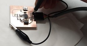
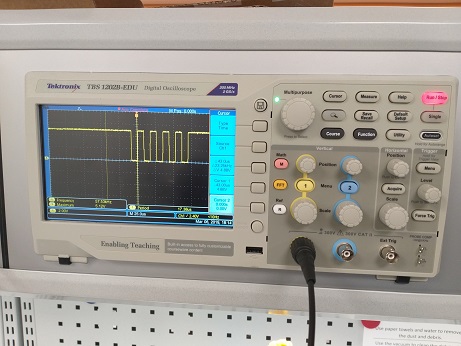
We used oscilloscope to check the signal by connecting the probe.
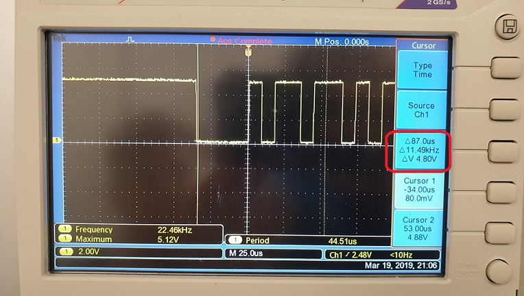
Typing a letter using keyboard, you can see the binary format of the letter in oscilloscope.
Using Putty, we typed U, S and B.
Binary code for “U” 01010101. This can be seen also in the signal, you need to look at it reversed, least significant bit (LSB) is sent first.
This week assignment was
Redraw the echo hello-world board
add (at least) a button and LED (with current-limiting resistor)
check the design rules, and make it
optional: simulate its operation.
Measure its operation
.Eagle
In this week I lerned basics on electronic,
I learned also to use Eagle and the process to design an electronic circuit Redraw an electronic circuit
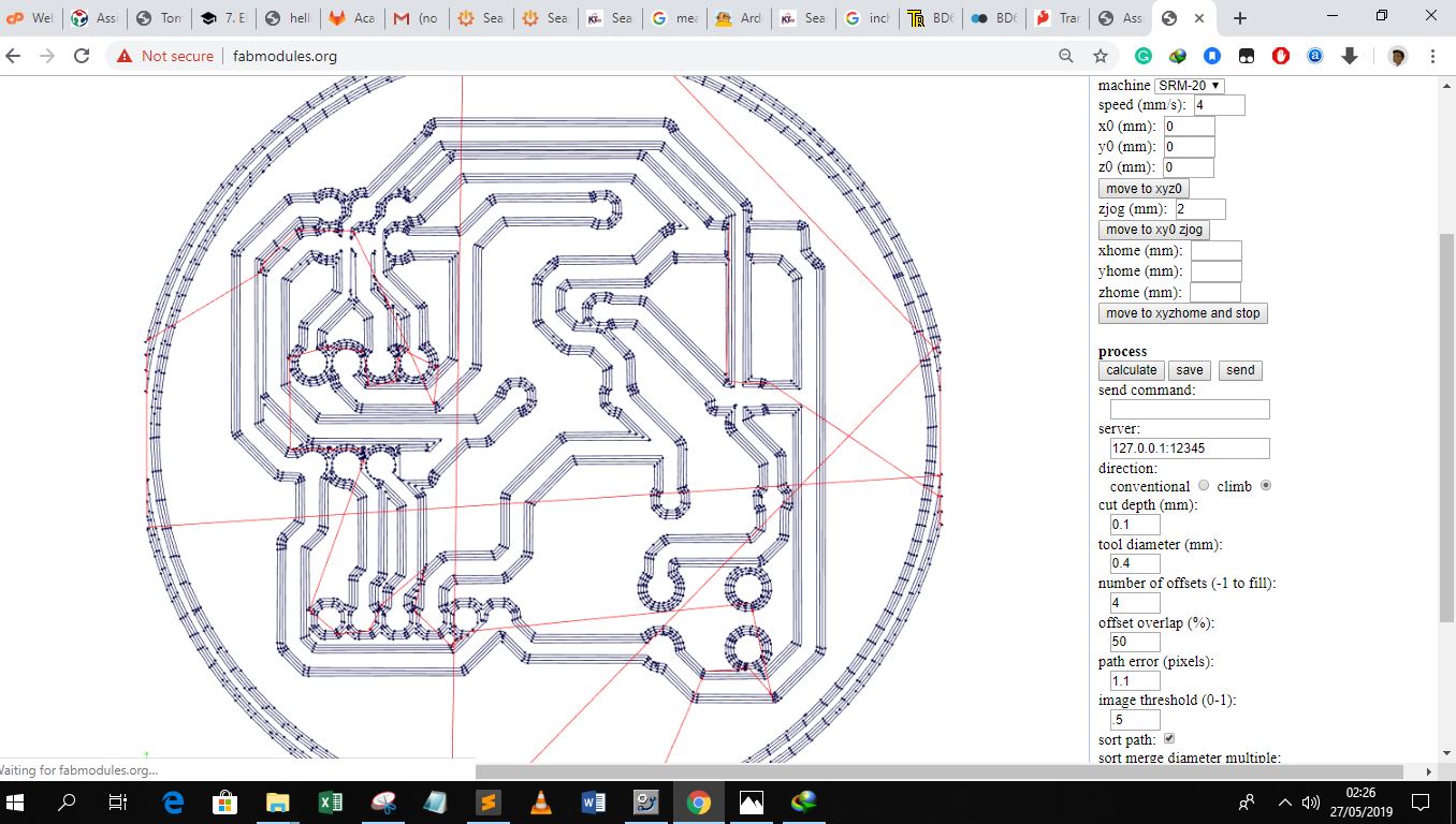
I learned to mill the board with PCB Machine
I first studied the electronic introduction then later
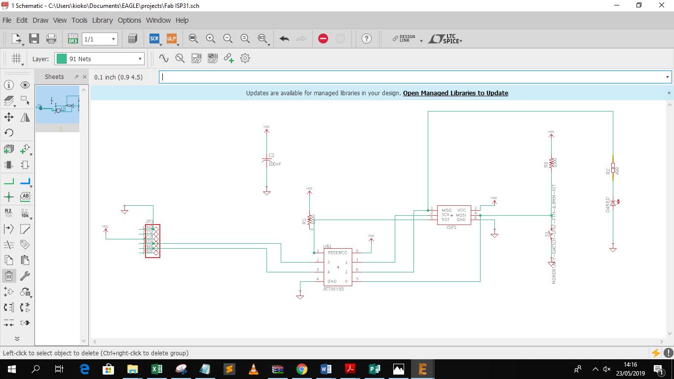
Copy the elementes like the tutorial into the EAGLE,
Add the properties and values according to the tutorial in diagram
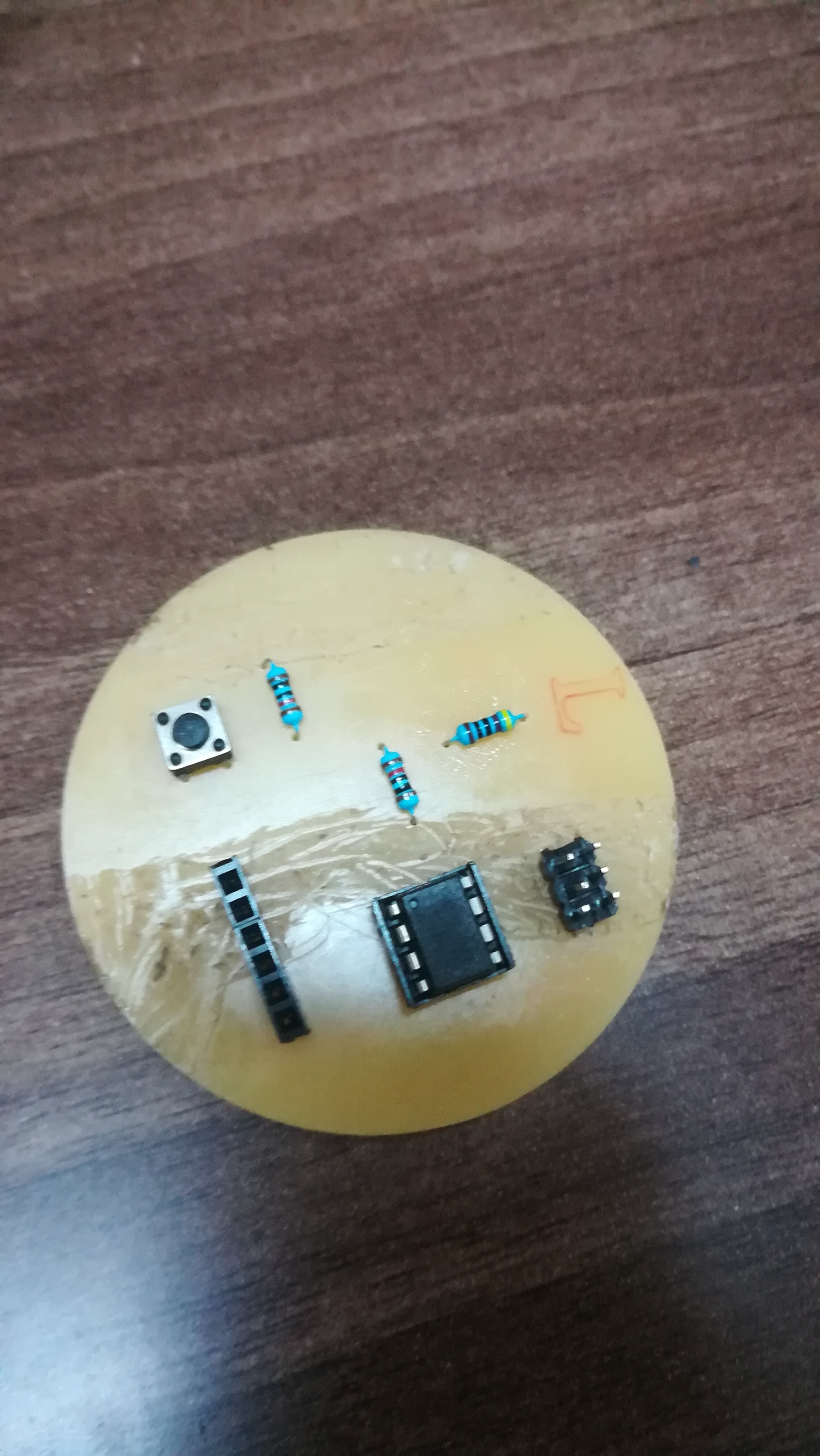
1. 10k resistor 1
2. 20 MHz resonator 1
3. 1uF capacitor 1
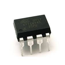
4. ATtiny 45 IC 1
5. 2x03pin header (AVRISP) 1
6. 1x06pin header (FTDI) 1
now its time to start doing the design wor(drawing hellow world board)
I created a new project:
At the Control Panel, right click “Project” 1.“New Project”
2. “New Project”
3. Right Click it to rename as “Echo Hello World”
4. Right click “Echo Hello World”
5. “New” - “schematics”
Click “Add Part” icon to add the parts in the above charts onto the schematics
Click “Net” icon to start wiring the parts
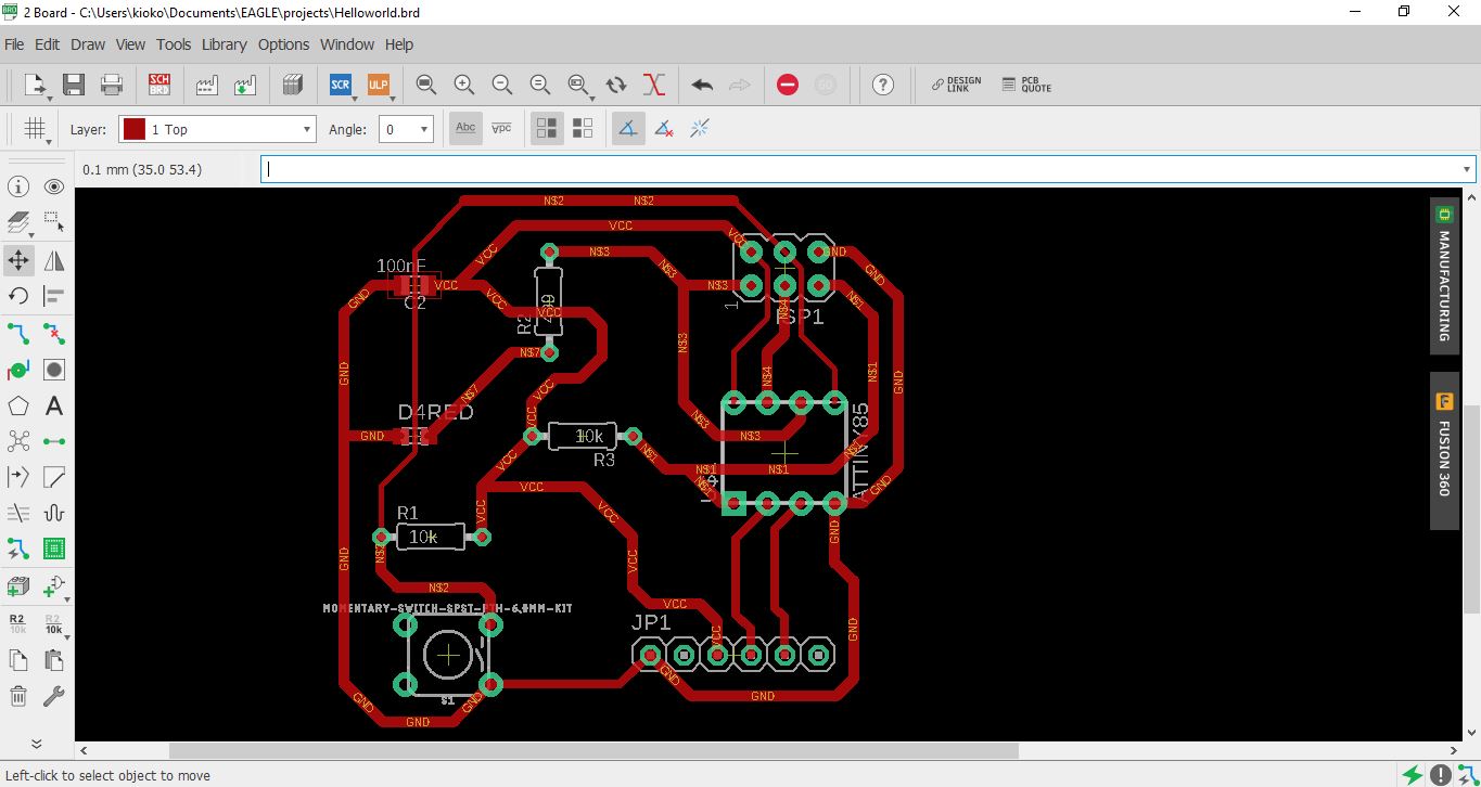
When finished wiring, I need to set the design rules
The design rules will be set in the Board Window. When click the icon of “SCH/BRD” to switch from schematics window to board window, it will ask to “create from schematics”, click “Yes”
Follow the “Read Me” file instruction to add Fab Design Rules.
Click “Load” and select the fabcity-designrule.dru file which I downloaded from the Fab Library and click “Open”
first i check out the pinout for the ATtiny 45
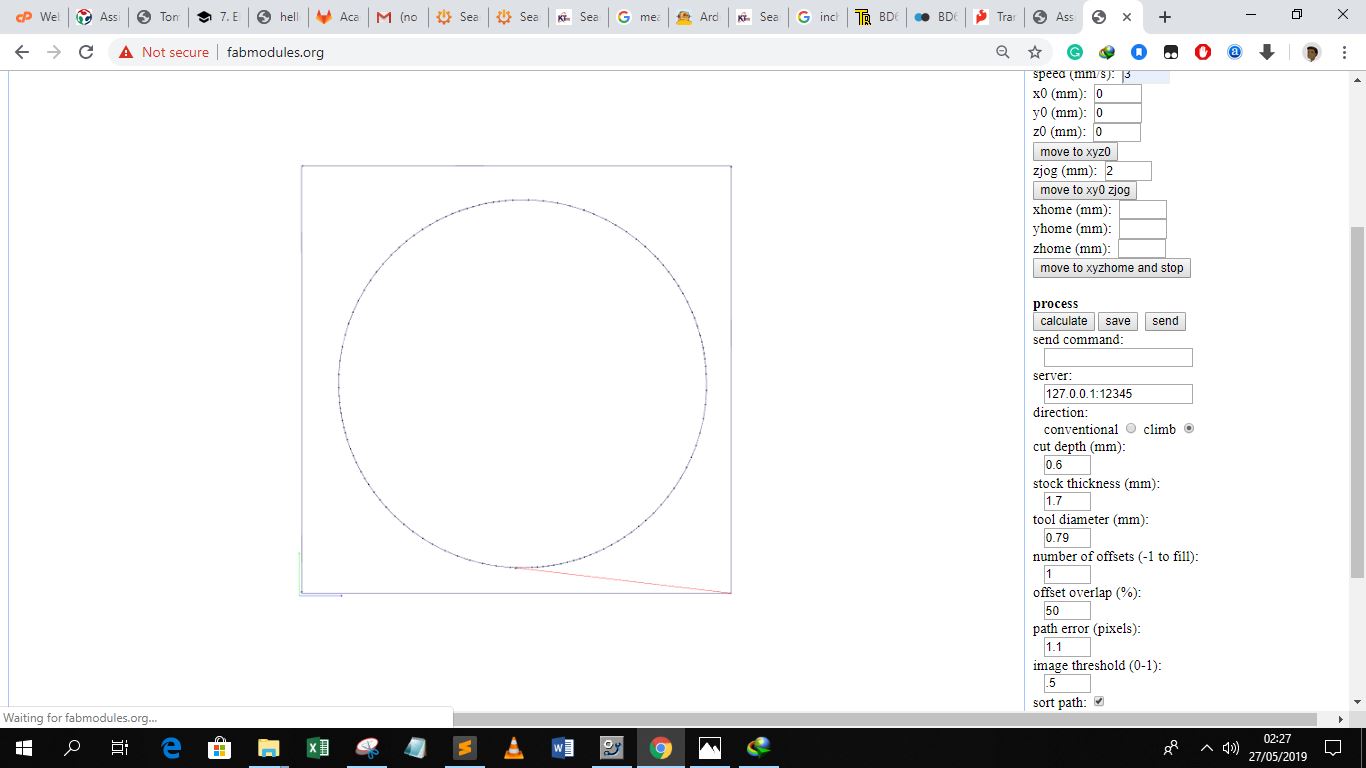
then i went about to design the actual board.
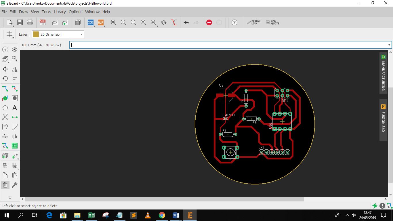
The next step involved generating the cam files
The first thing I did with the LEDs was figure out which wire (its called an electrode) was positive and which was negative.
Generally speaking the longer wire is the positive electrode and the shorter wire is the negative electrode.
Once I knew what was positive and what was negative I just had to remember what the voltage of each LED was.
All my LEDs recommended 20mA of current. 20mA is standard for most LEDs.
I use the link below as a guideline
Instructables LED and resistor Tutorial
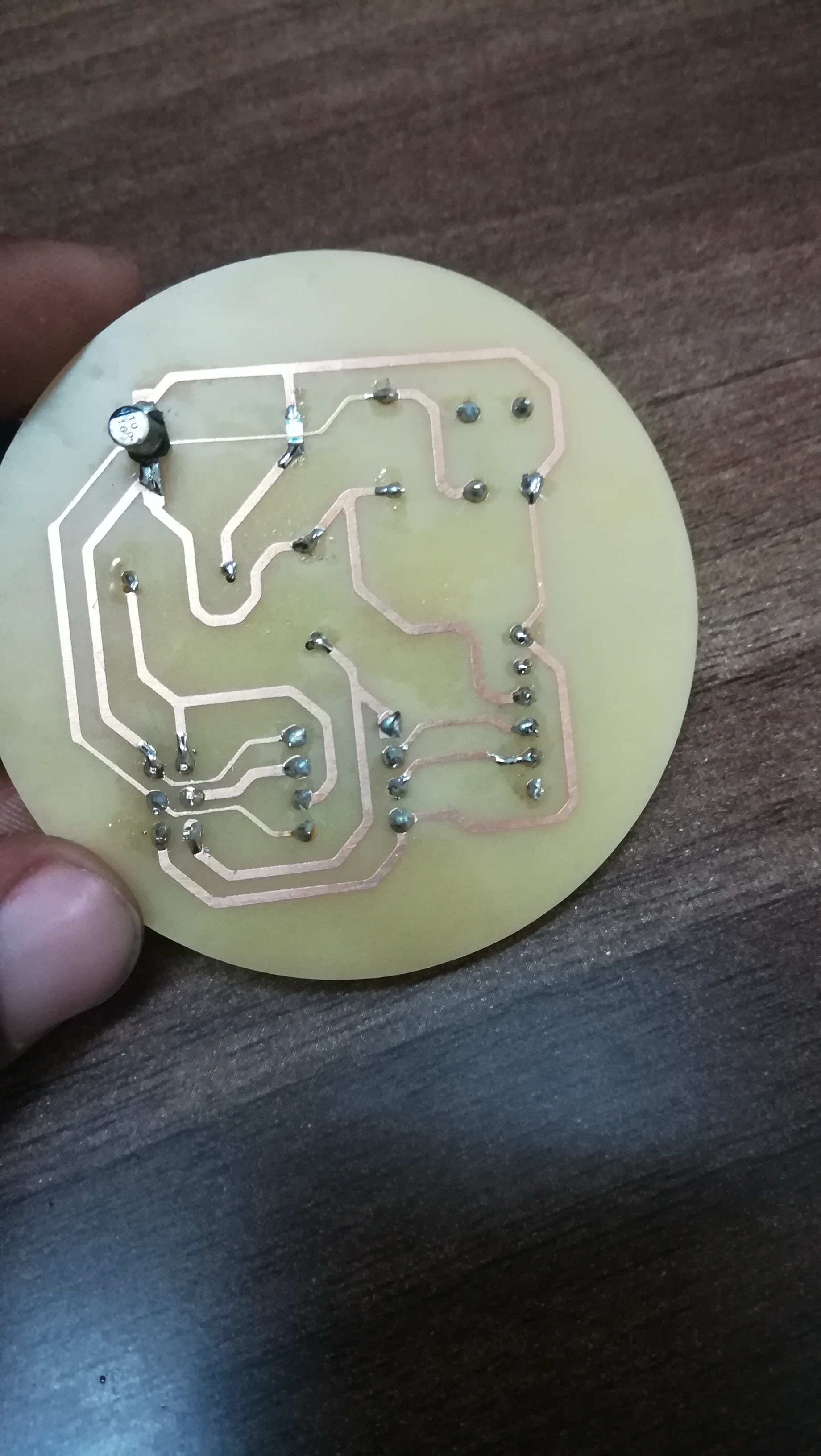
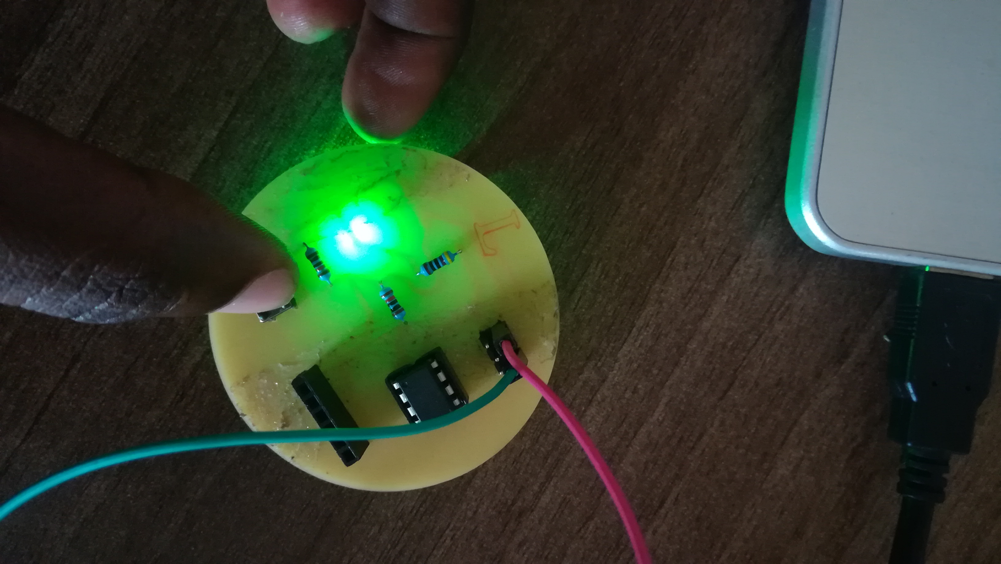
After soldering i connected my board to the programmer
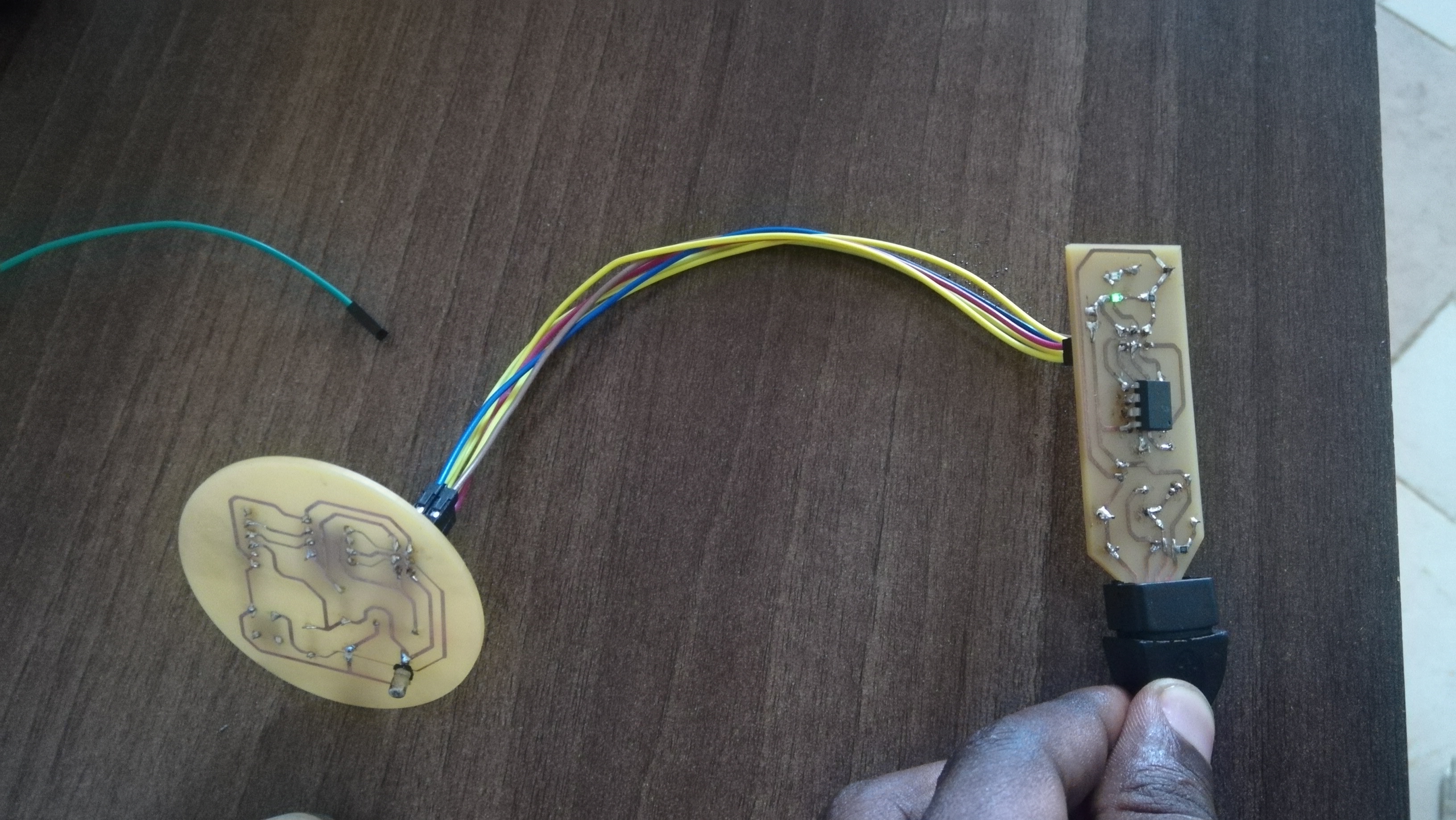
tested my board and it worked out well when I pressed the button it lights
This was the difficult part of the assignment, i had no background in electronics,
but with the help of electronics guys i had around i manage to to all this