This week assignment was
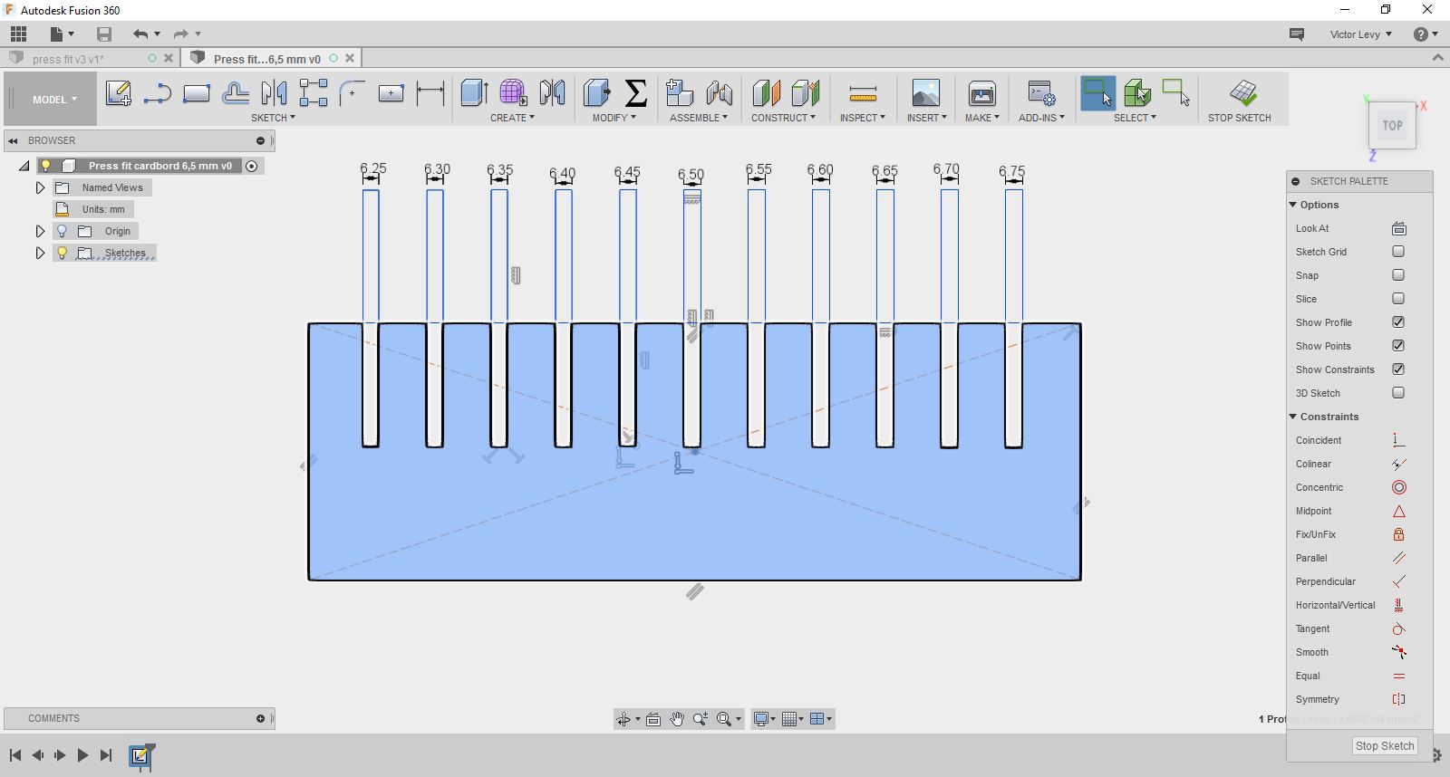
Make lasercutter test part(s)varying slot dimensions using parametric functions
testing your laser kerf and cutting settings (group project)
cut something on the vinylcutterdesign, make,and document a parametric press-fit construction kit,
accounting for the lasercutter kerf, which can be assembled in multiple ways
1.Fusion 360
2.inventor
My group members are Kioko, Derck and cedric . first we learned about Kerf. Factors affecting kerf. What is vector and raster mode in cutting?
How it influences the laser parameters such as power, frequency and speed during cutting ?.
The laser burns away portion of a material when it cut through.
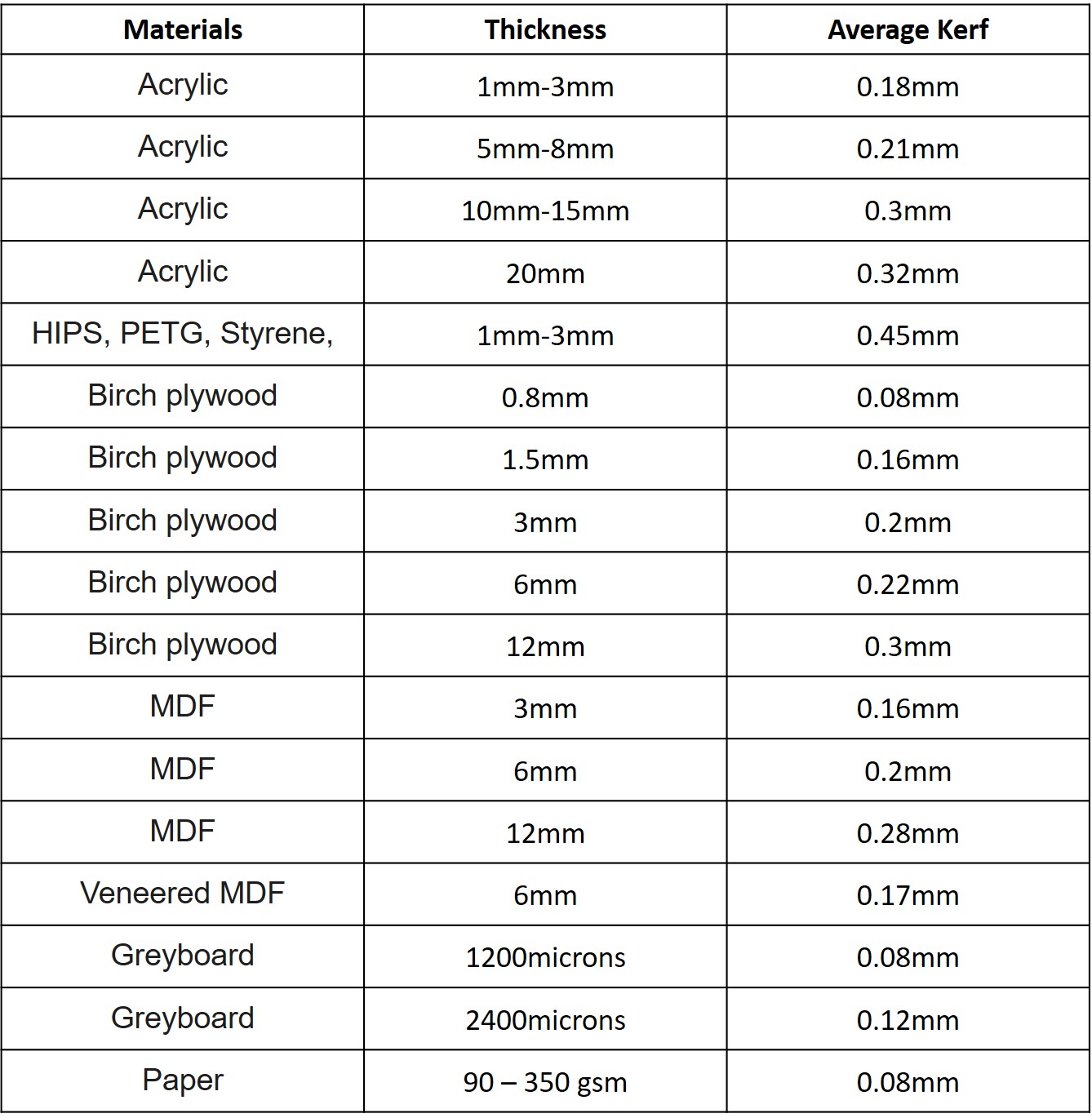
This is known as laser kerf and it ranges from 0.08 mm – 1mm based on the material type and other conditional factors.
We have used kerf of 0.02 mm for our laser cutter.
Some of the applications of various materials with thickness and average [Kerf]
(http://www.cutlasercut.com/resources/tips-and-advice/what-is-laser-kerf) are listed in the below table,
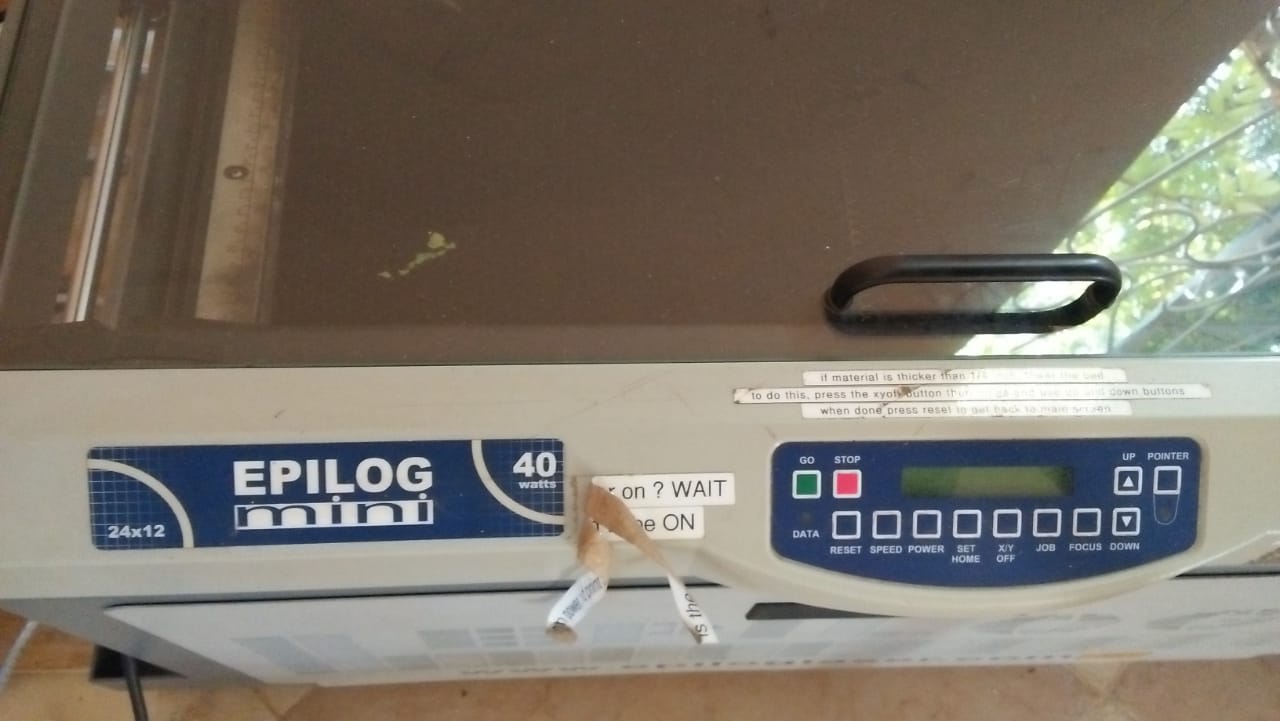
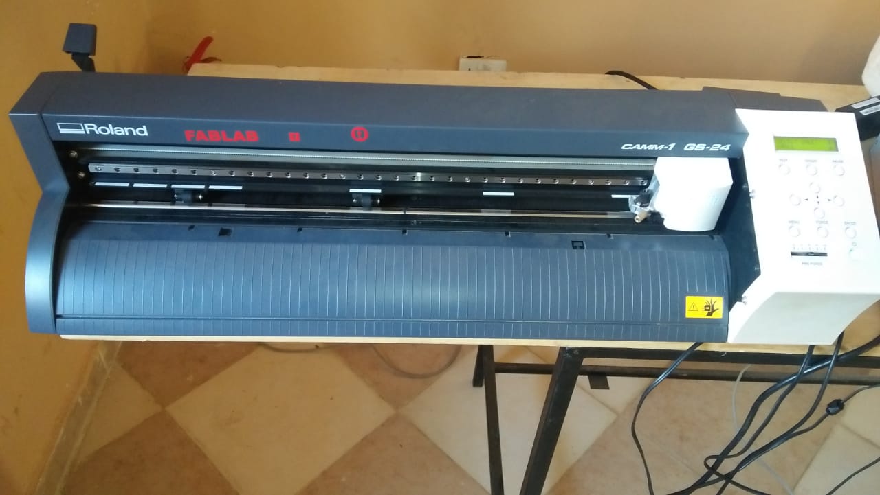
JOG - used to set the origin for starting the cutting, and it is selected with the up and down arrows.
A joystick is used to position the laser head at the start point and when in position, press the joystick to set the Jog.
FOCUS - sets the correct height of the table of the cutter. A 2-inch aluminium piece is used to set the height by using the joystick’s
up and down motions to position the table. When in place, the aluminium is removed, and the focus is set.
JOB - used to select the work to be cut from the printing queue. The joystick is again used,
and when the right job is selected, an estimated cutting time will be displayed on the control panel.
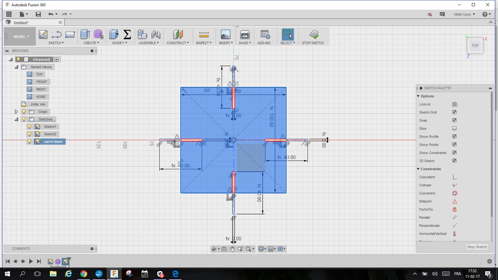
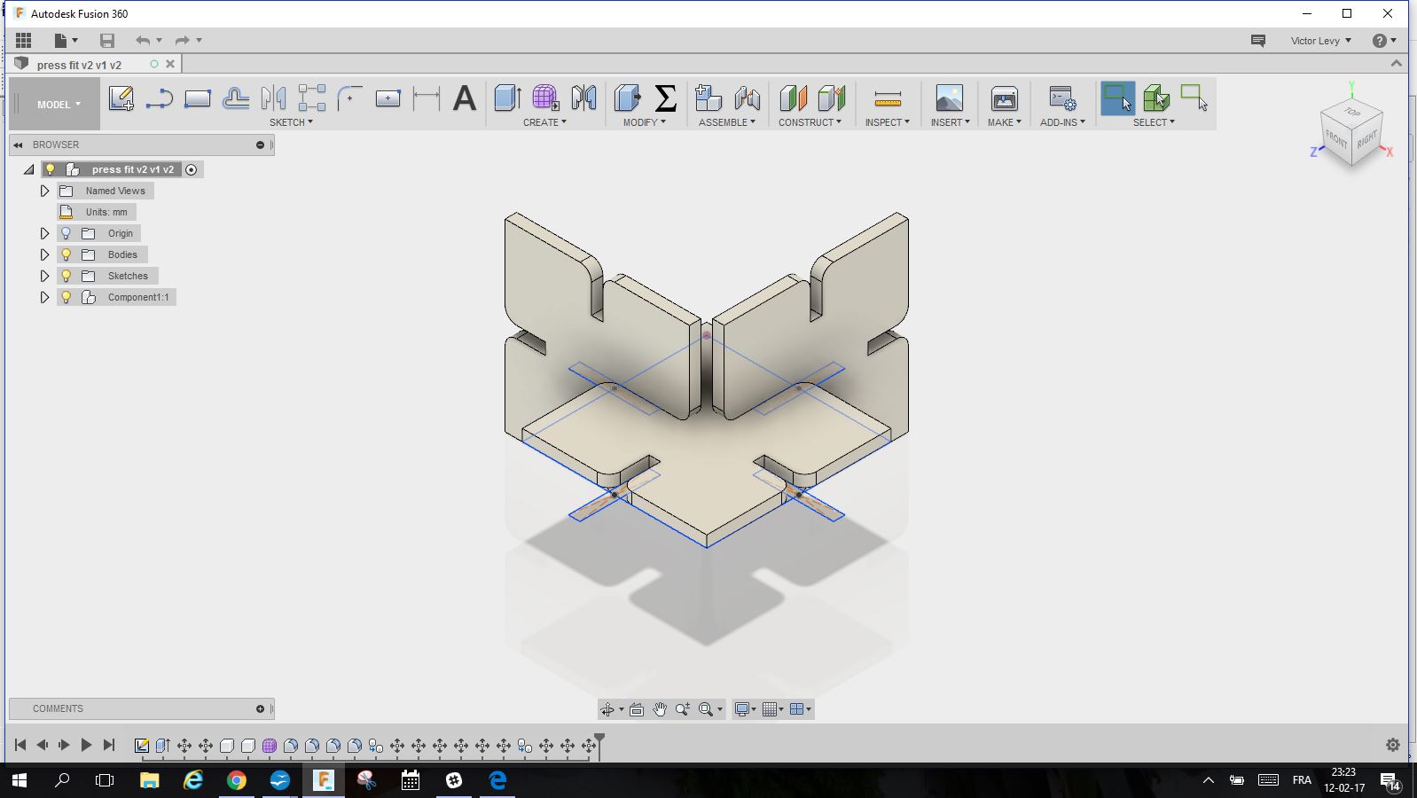
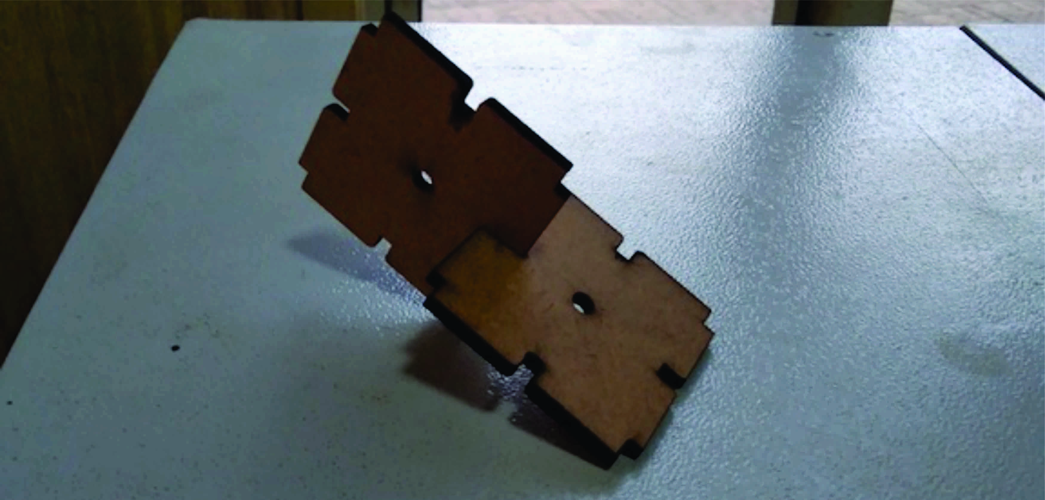
I designed the simplest joint,I started from there
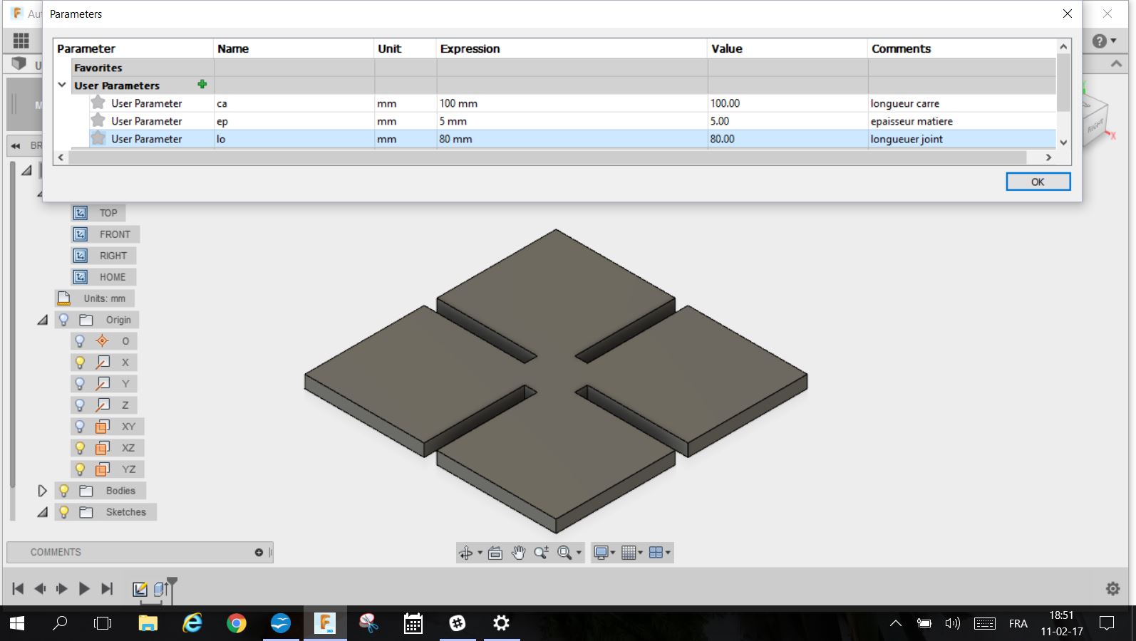
Made it parametric,done on fusion 360,
Made by the function in CONSTRUCT
Change parameter where you put a name and dimension in a datasheet
Then I extrude it the first type of joint
joining
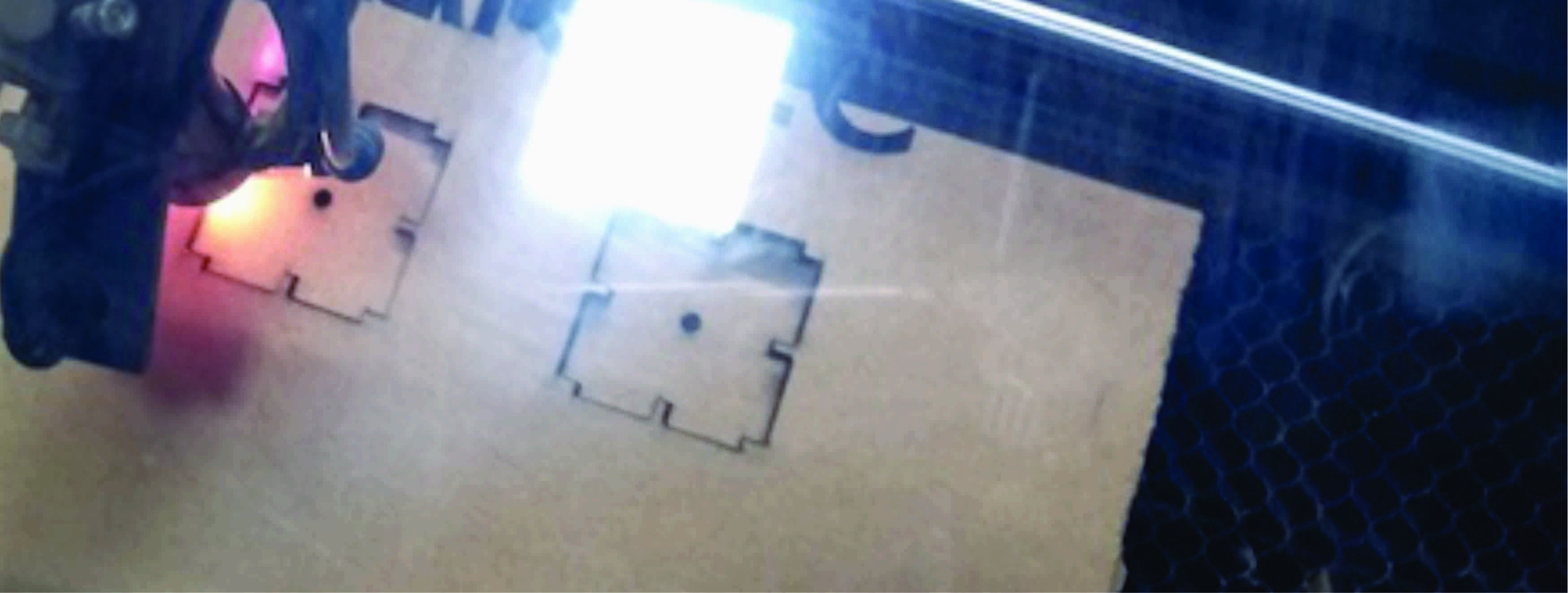
1.Set the focus before starting the print.
2.You can use the Laser dot switch on the control panel to set the focus points.
3.This switch will project a red dot on the material below.
4.Adjust the Z-axis in a way that the two red dots perfectly coincide with the red dot
5.The origin is always from the top right of the frame but it can be adjusted manually using Orgin and Enter button.
I was to test the speed and power combination for our laser.
Key output was to check at what speed and power the material can be cut.
speed (30 to 300 mm/sec)
power (10 to 100 percent)
The speed should be lower with high power to allow material to burn efficiently
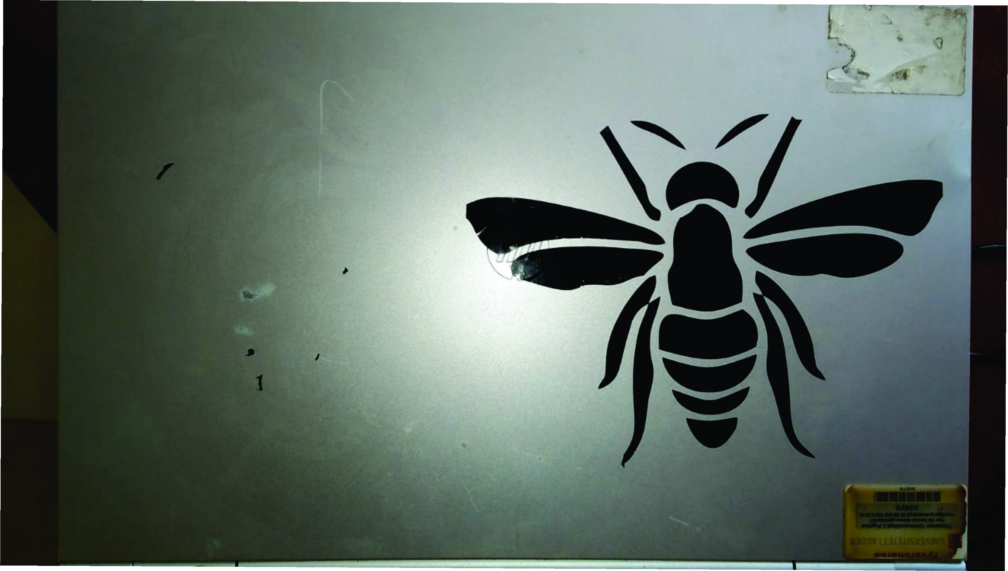
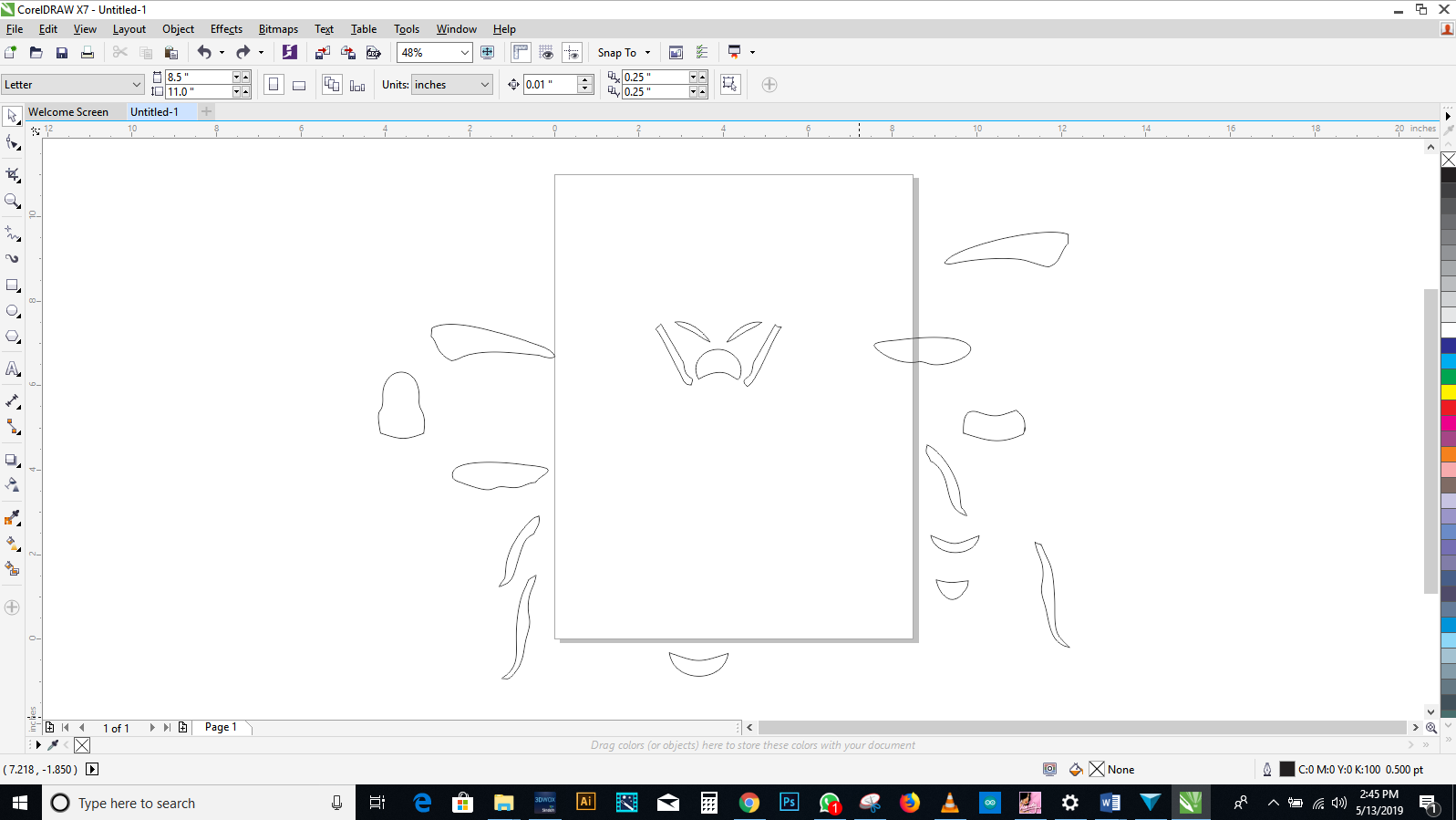
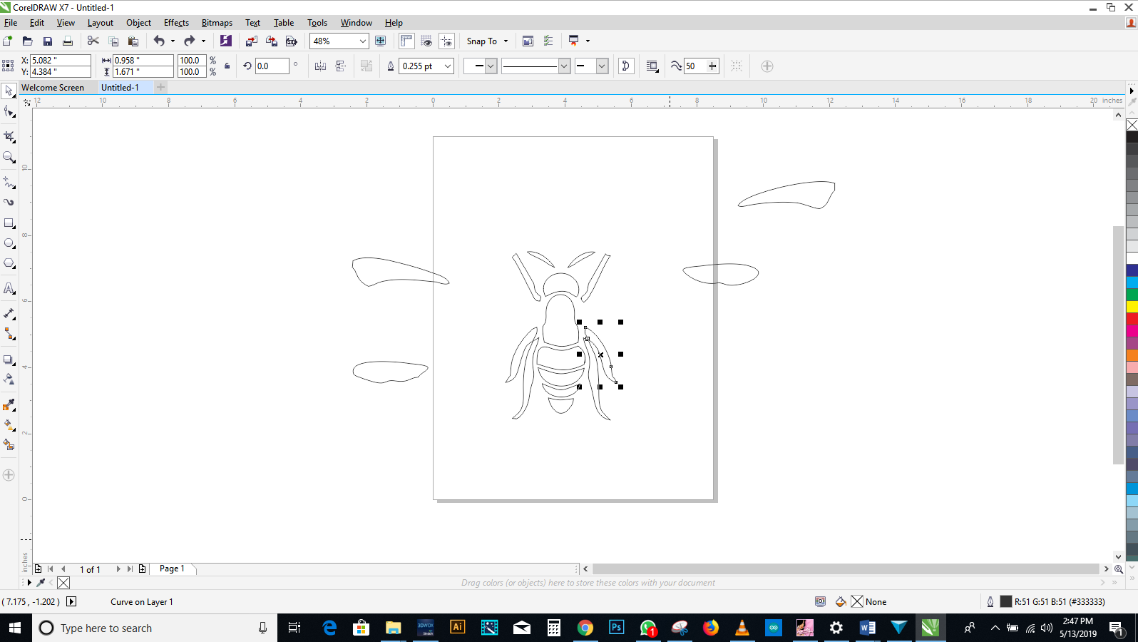
I decided to draw and design a beetle i used a picture for reference
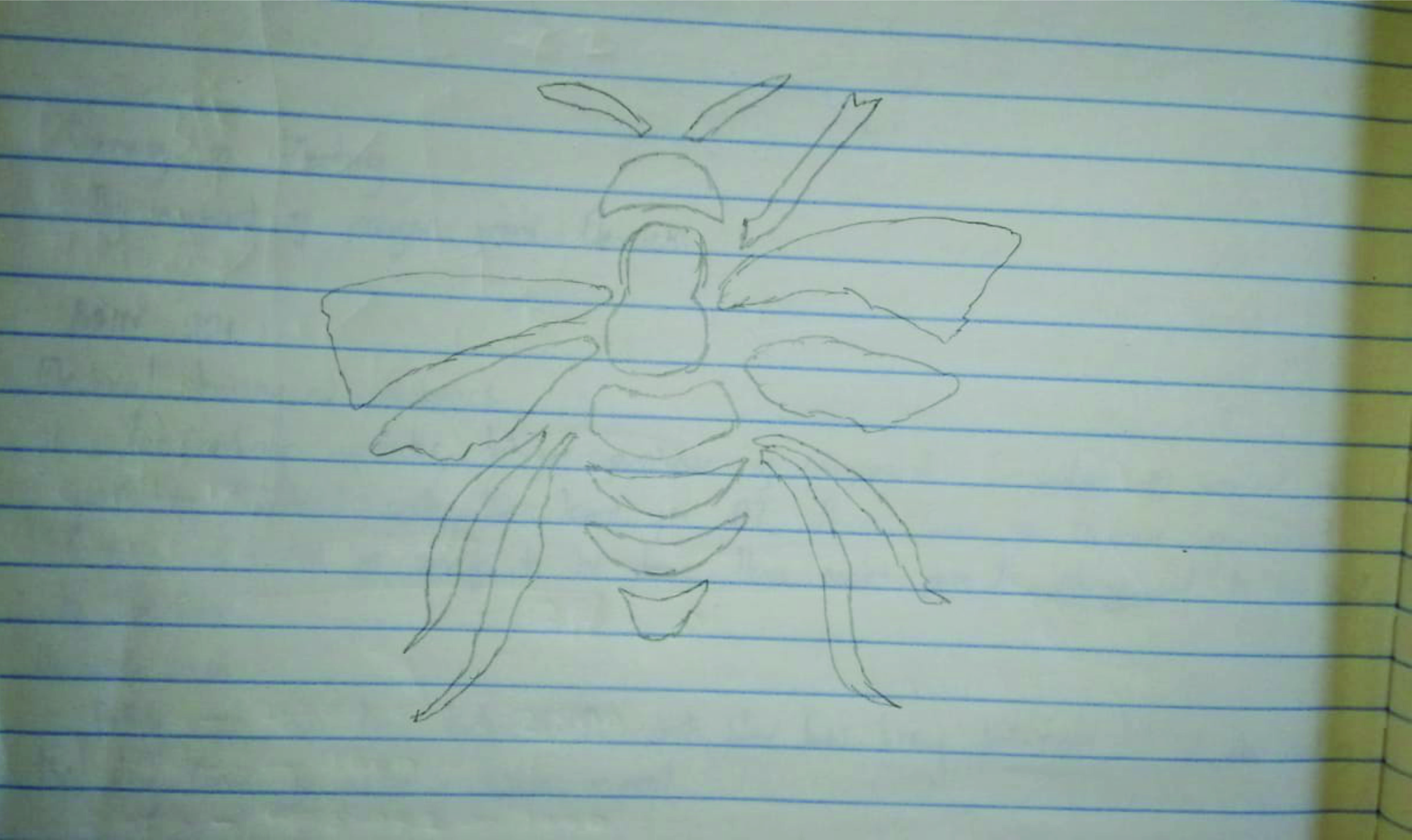
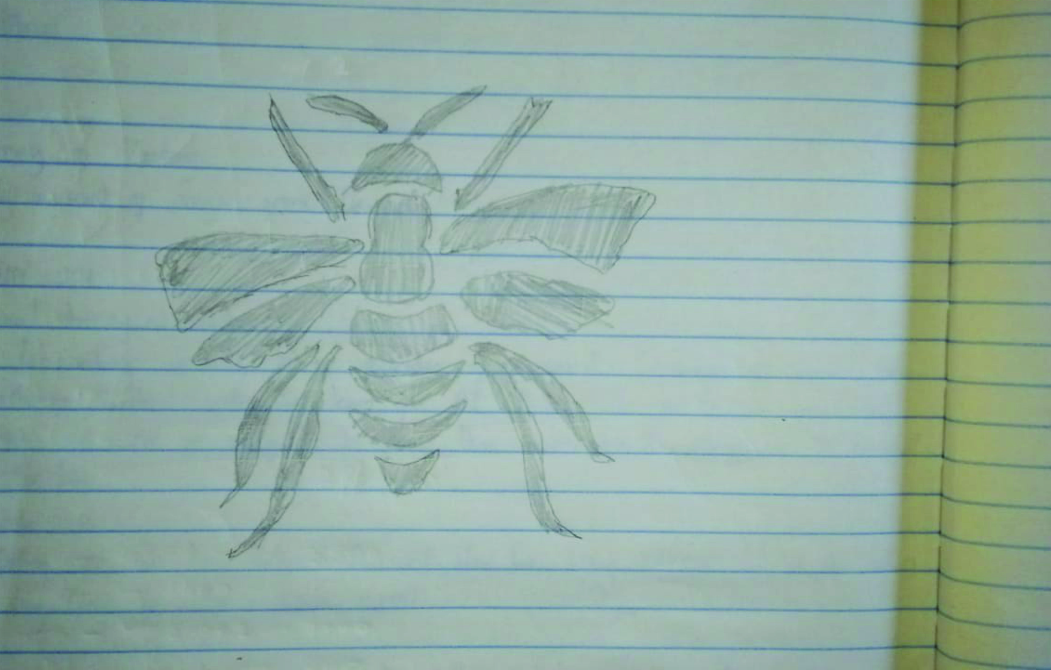
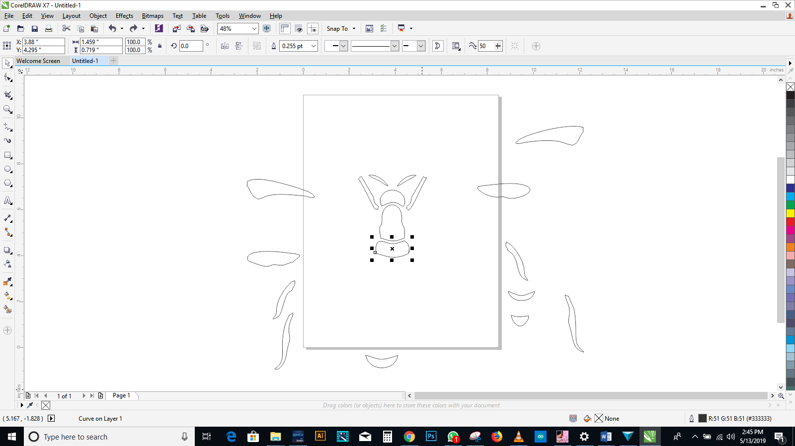
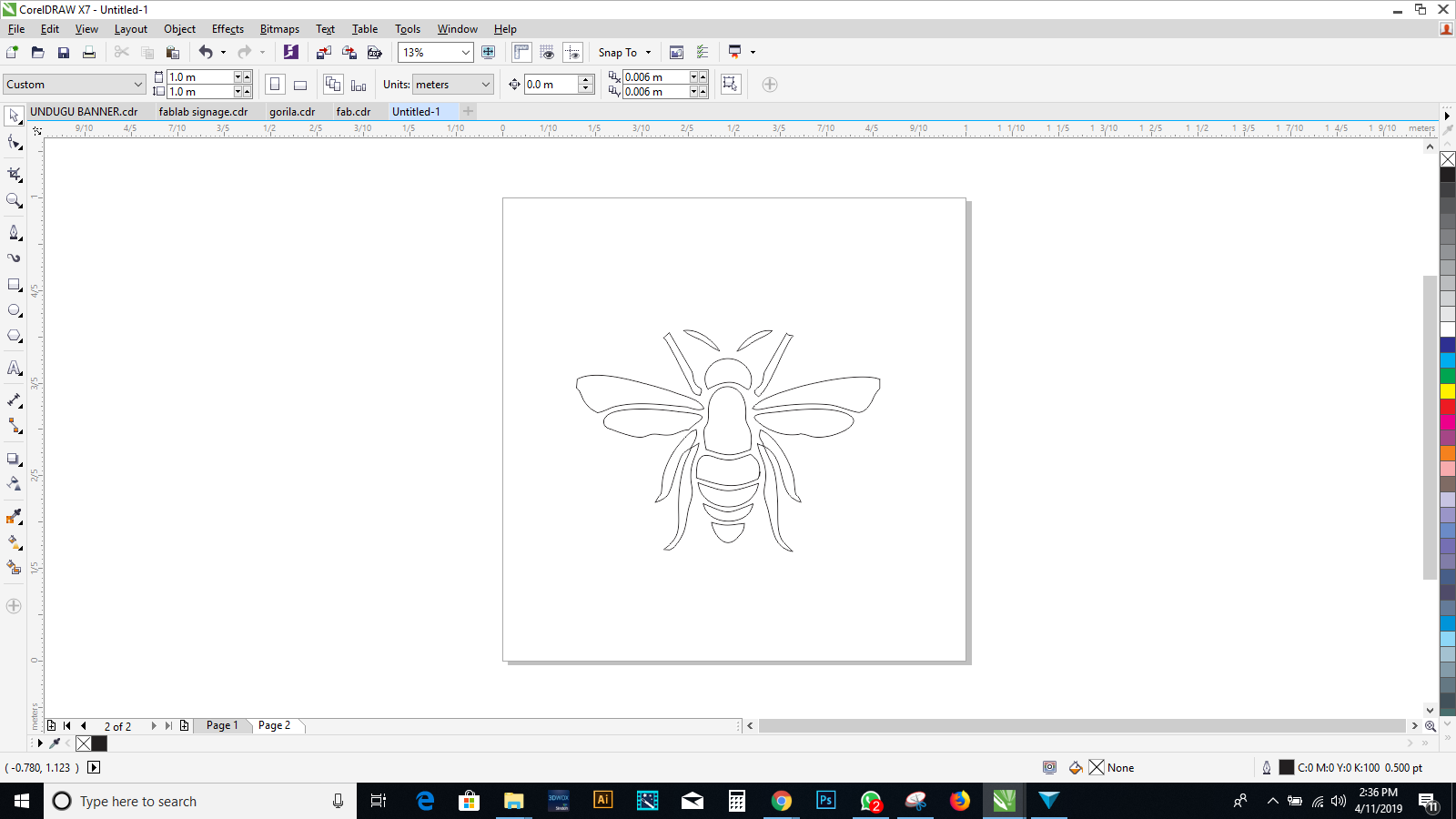
I opened corel draw and usining diffrent primitives i design my beetlee
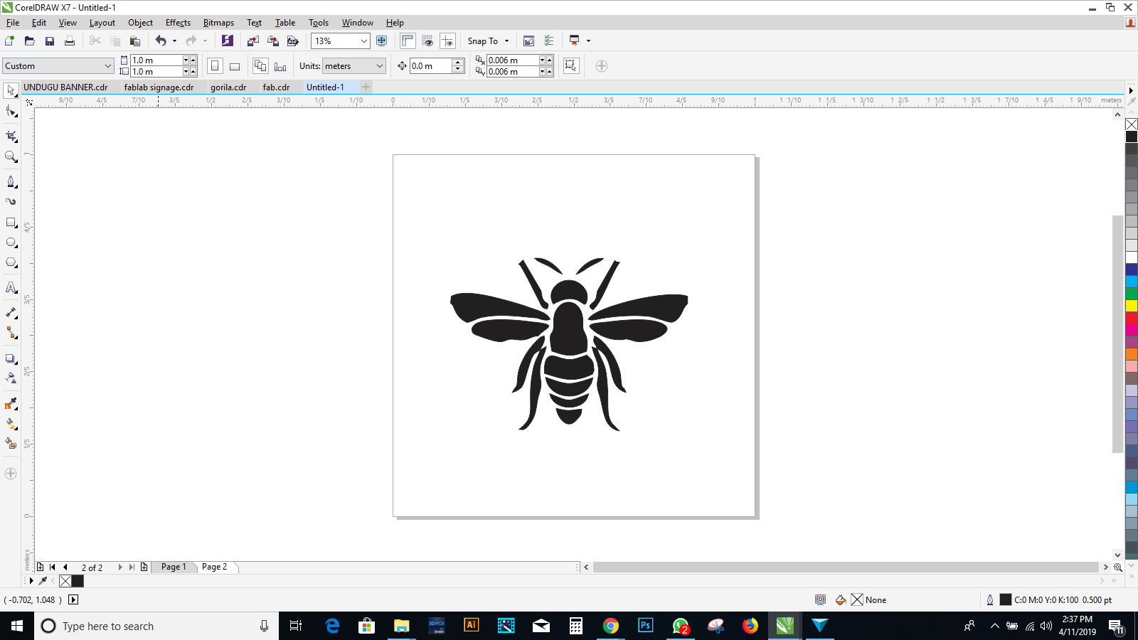
I also tried colouring it to chek how it will look like after cutting it on a black vynile sheet
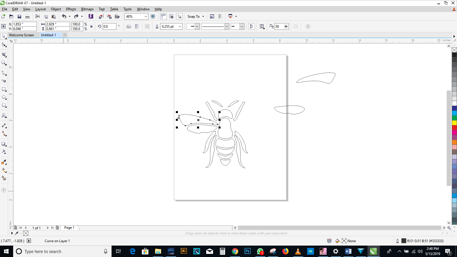
after i have quick traced my image i descided to assemble the parts together


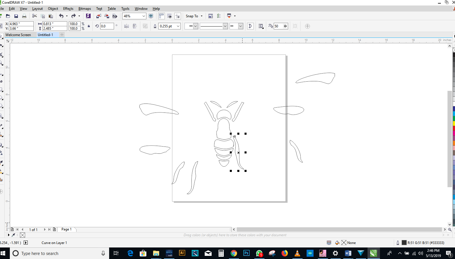
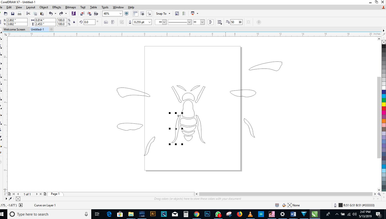

I made the appearance look black to have the clear picture of my final bee since i will use black vynile sheet
i checked on our store to find three different types of vynile sheet
and i desided to use the black one
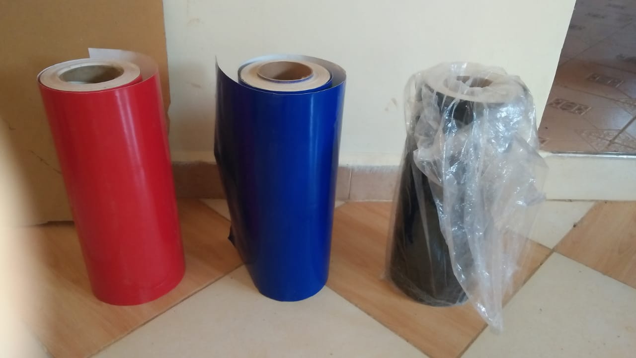
I cut a small vynile sheet to use, with my white masking tape ready
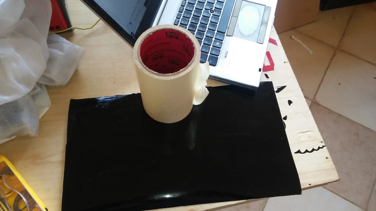
setting the vynile pice along the white line
then i selected the piece since it was not a roll
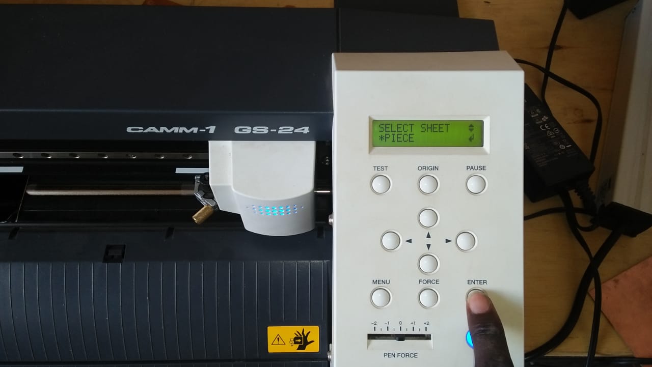
setting the origin
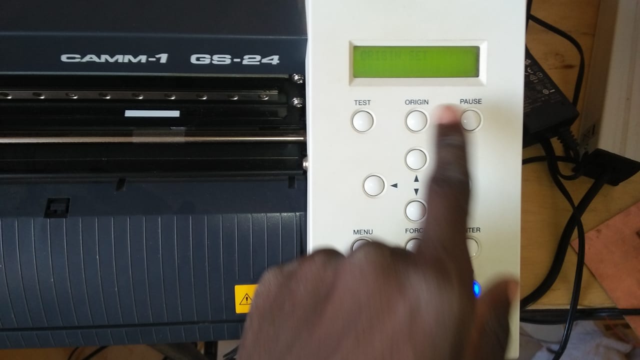
Getting reading from the machine
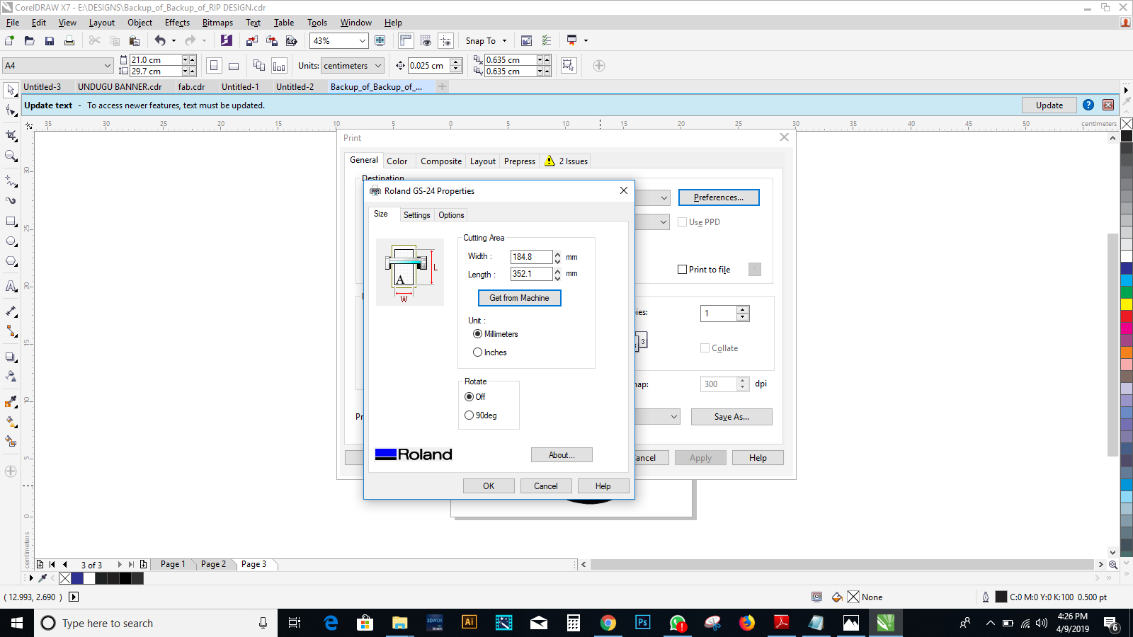
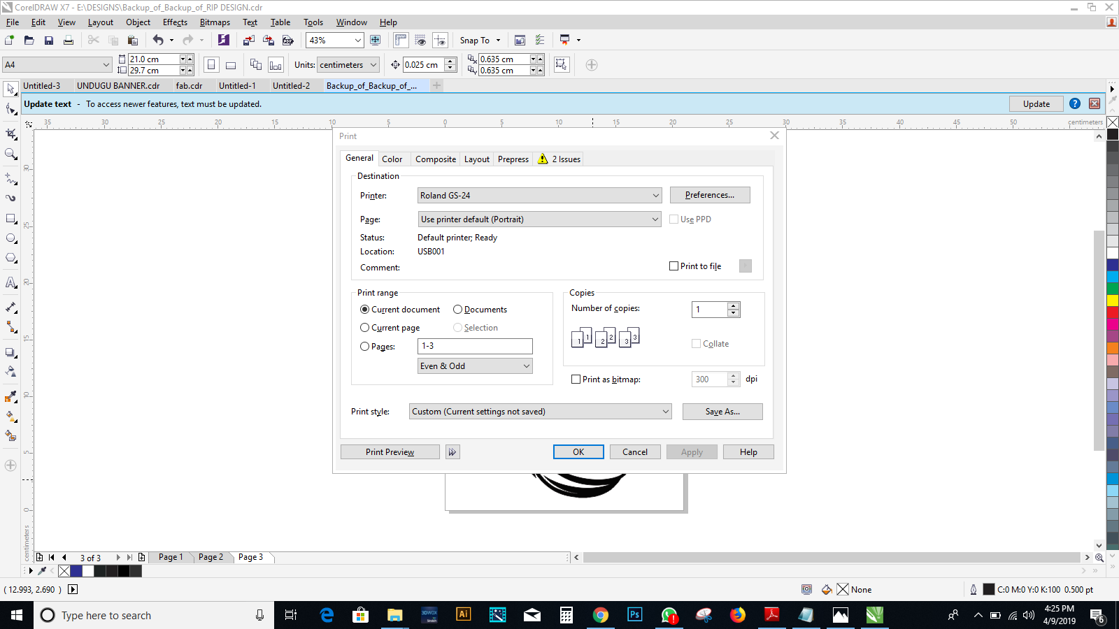
Sending the file to print
Sticking
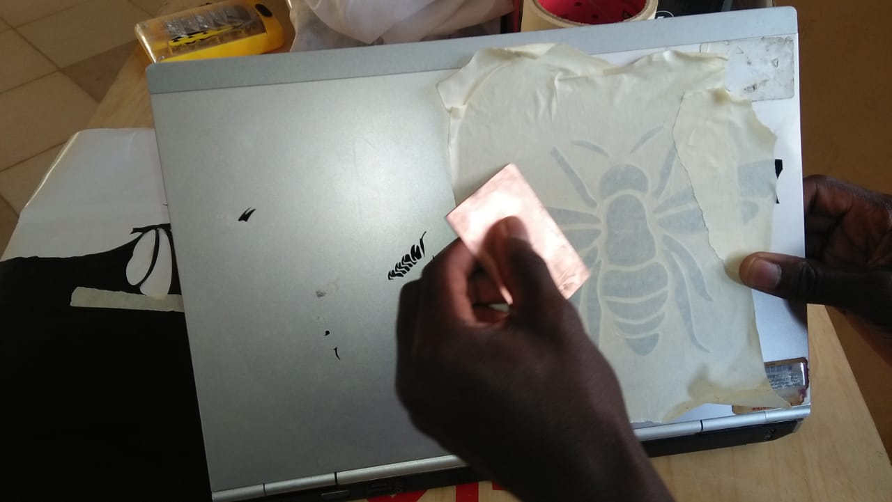
Finaly