design, build, and connect wired or wireless node(s)
with network or bus addresses
This week, we have to learn more on communications protocols and network with microcontrolers.
I plan to use an ESP8266. Then I connect 3 Attiny44 in serial with differents addresses.
ESP8266
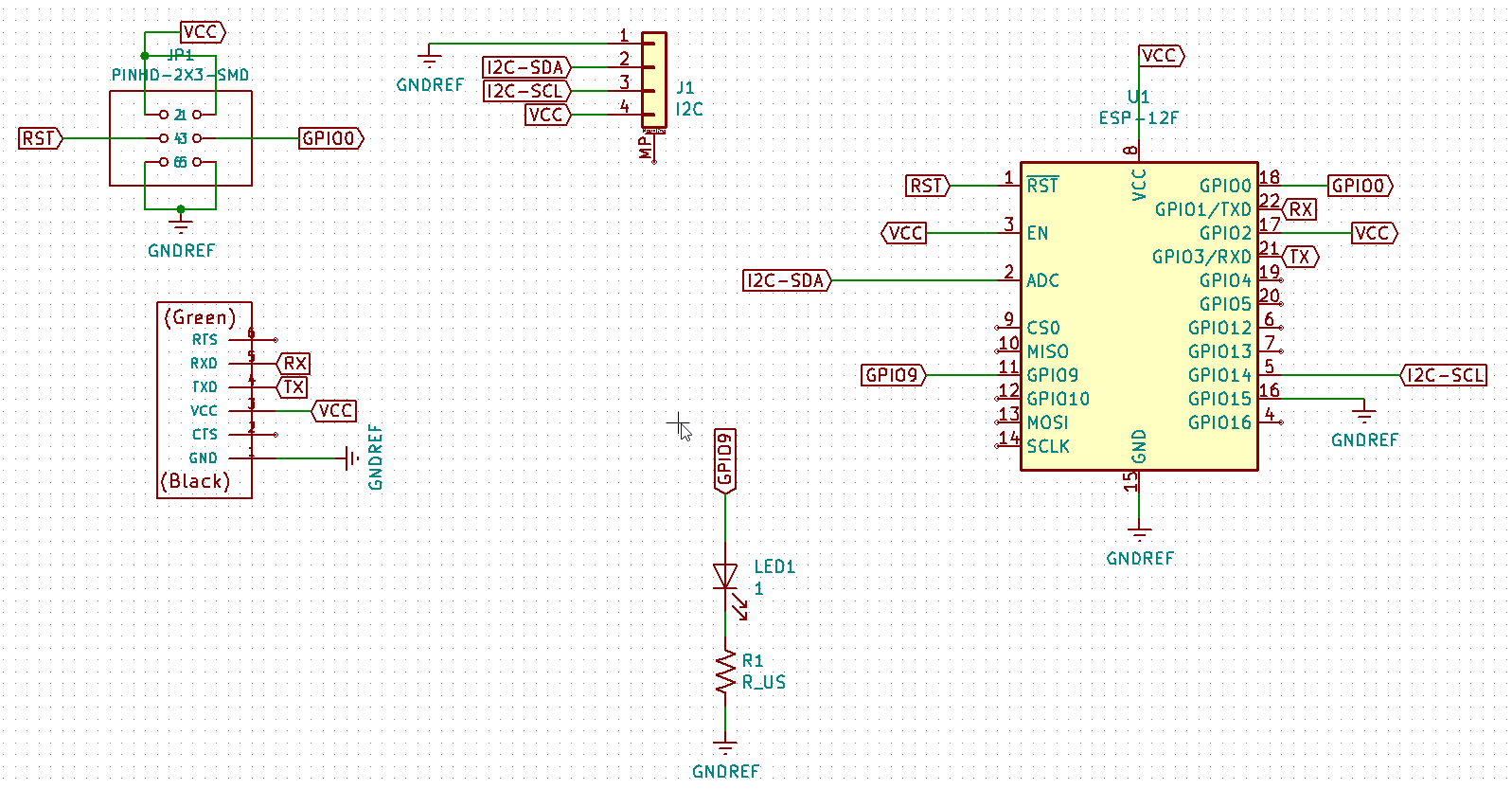
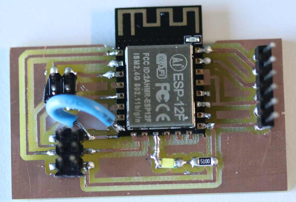
I’ve designed a board with an ESP8266 using Neil’s board but with modification :
I want to be able to flash during the bootloader but to have also the serial connections,
to have access to the boot pin and to connect an I2C board.
I’ve discovered that the GPIO0 has several functions https://www.elecrow.com/download/ESP-12F.pdf
review
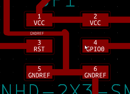
I design several pins to connect either to the ground or to the high value.
the same for the pin RST.
i added an LED with a resistor to have a visual check.
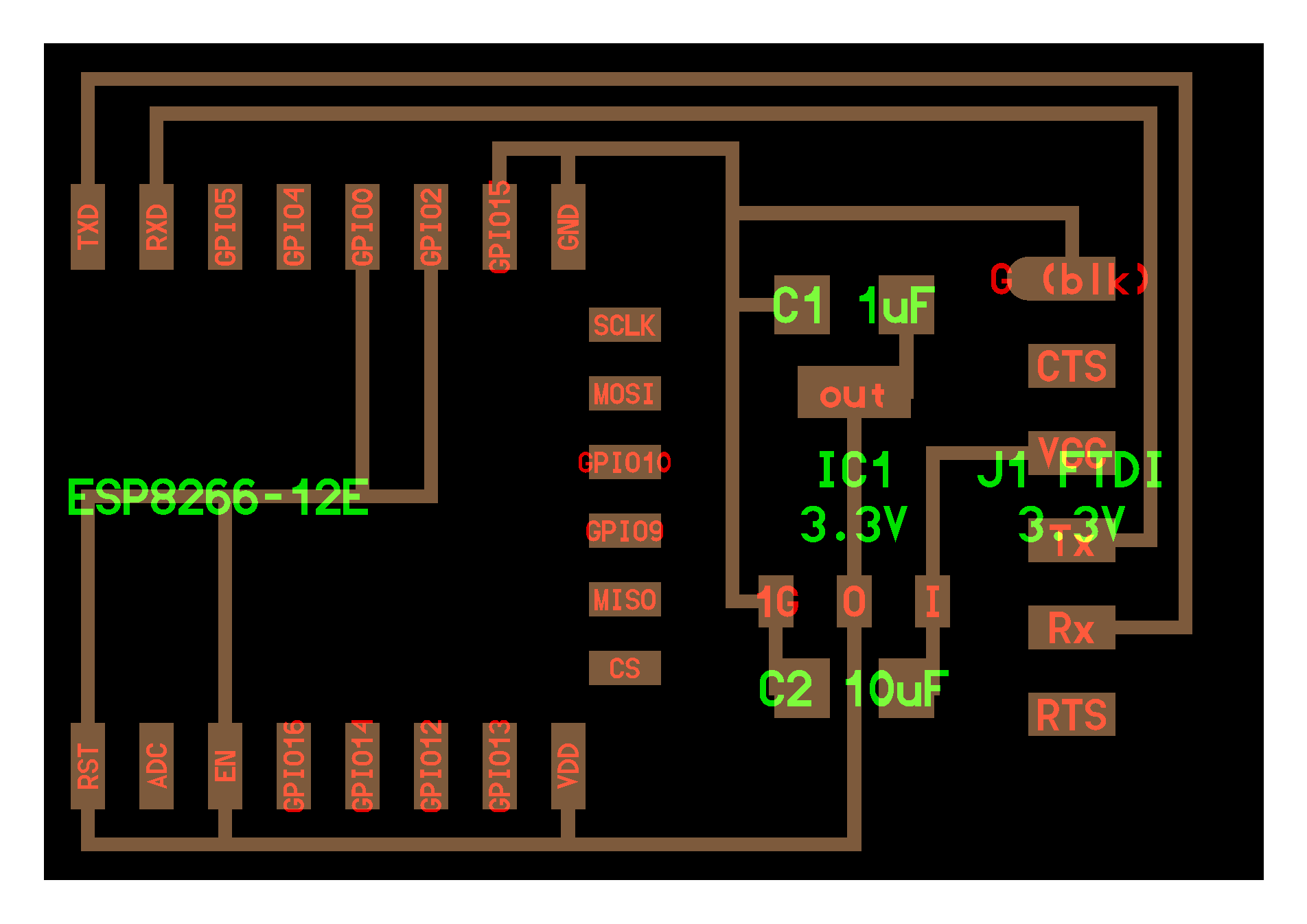
Design
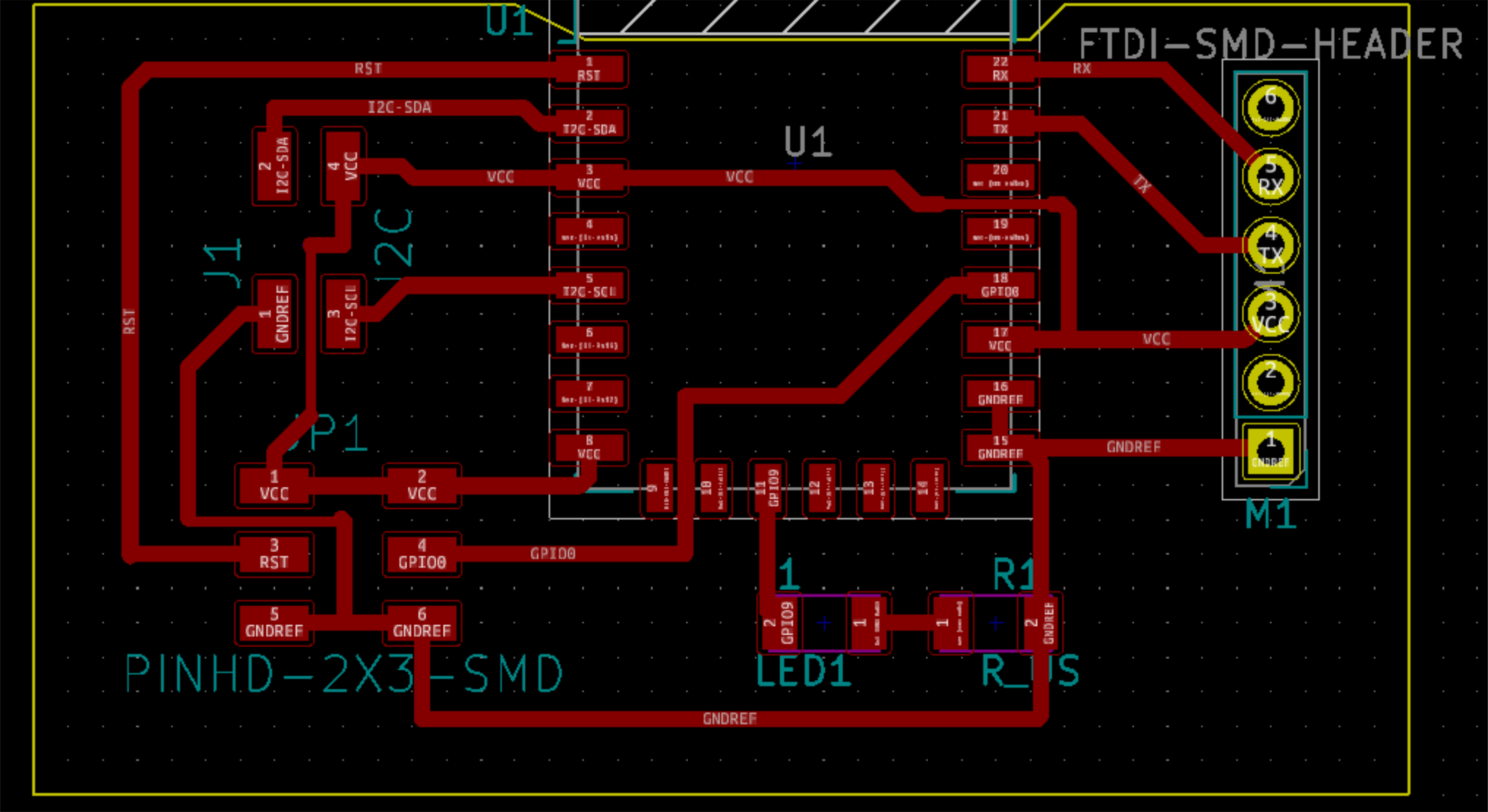
Milling and soldering

ESP8266
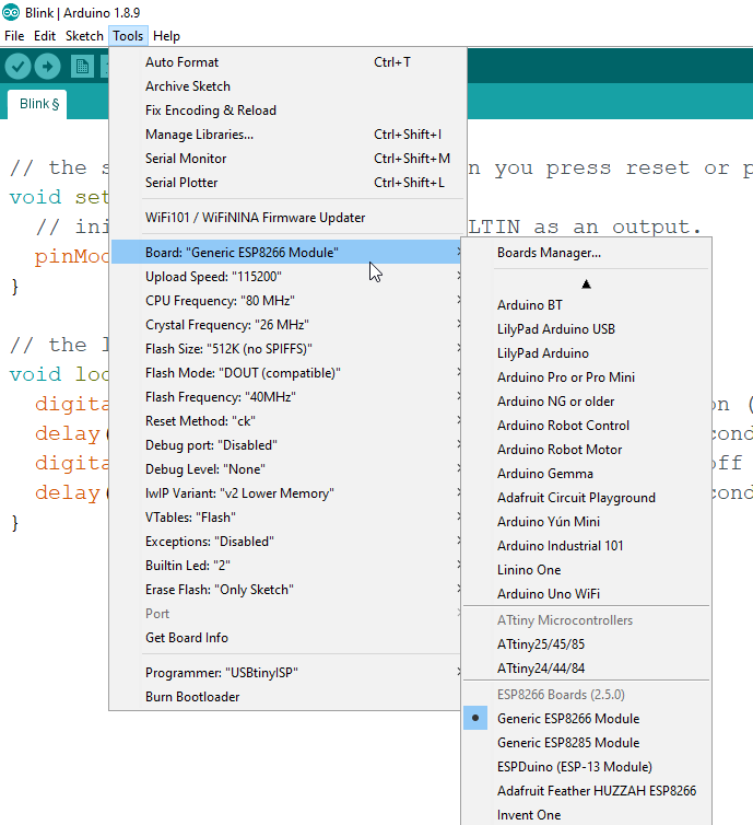
I tried programing and flashing the code but i did not succeed,
so i checked the electronic connection and wer ok
I select the correct board in arduino.
Serial communications
I use 2 boards made in the input and output week.
I programm the output board to be the master and to send a “1” message then a “2” message.
The 2 other boards light up the LED if they receive the correct number .
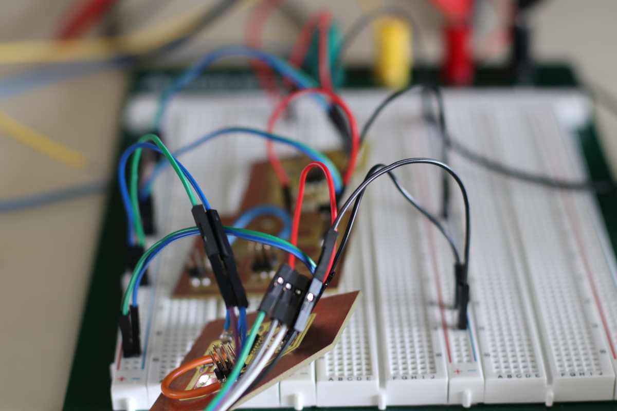
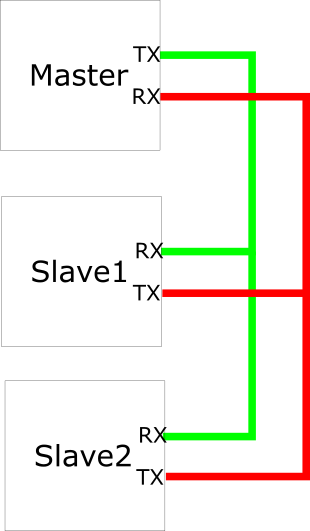
All the board are powered by the same 5V , with a red and a black wire.
They share their Tx and Rx with a blue and green wire.
code
#include
#define rxPin 0
#define txPin A1
SoftwareSerial serial(rxPin, txPin);
void setup() {
pinMode(rxPin, INPUT);
pinMode(txPin, OUTPUT);
serial.begin(9600);
}
void loop(){
serial.print(1);
delay(2000);
serial.print(2);
delay(2000);
}
One receptor board
#include
#define rxPin 0
#define txPin A1
#define LED 7
#define button 8
int rxbuffer;
SoftwareSerial serial(rxPin, txPin);
void setup() {
pinMode(rxPin, INPUT);
pinMode(txPin, OUTPUT);
pinMode(LED, OUTPUT);
digitalWrite(LED, LOW);
serial.begin(9600);
}
void loop(){
rxbuffer = serial.read();
if(rxbuffer == '1'){
digitalWrite(LED, HIGH);
} else if(rxbuffer == '2') {
digitalWrite(LED,LOW);
}
delay(1000);
}
The other receptor board
#include
#define rxPin 0
#define txPin A1
#define LED 7
#define button 8
int rxbuffer;
SoftwareSerial serial(rxPin, txPin);
void setup() {
pinMode(rxPin, INPUT);
pinMode(txPin, OUTPUT);
pinMode(LED, OUTPUT);
digitalWrite(LED, LOW);
serial.begin(9600);
}
void loop(){
rxbuffer = serial.read();
if(rxbuffer == '2'){
digitalWrite(LED, HIGH);
} else if(rxbuffer == '1') {
digitalWrite(LED,LOW);
}
delay(1000);
}
The files
Design FILE