Measure the power consumption of an output device.
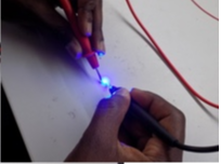
Our group members are, (Derick, Kioko and Cedric) we measured the power consumption of a 5 mm LED and an RGB LED.
The consumption of the LEDs was measured by directly powering them with a variable power supply and varying
the voltage and current in order to measure the resulting effect on the brightness of the LEDs.
If current is increased the LEDs brighten and if decreased, the LEDs become dimmer.
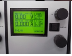
Observations during measuring process below:
we started the process with 5 mm LED, testing the effect of varying the voltage and current on the brightness.
If current is increased the LEDs brighten and if decreased, the LEDs become dimmer.
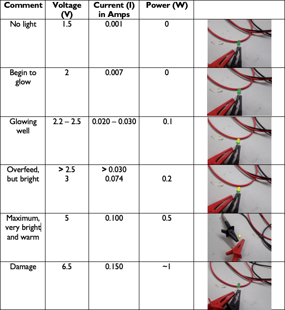
This LED has Forward Voltage ranging from 2 - 4 V. 2 - 2.6 V for Red, 3.2 - 4 V for Green, and 3.2 - 4 V for Blue.
The absolute maximum ratings for the Forward Current (the current flowing across the LED from positive to negative in order for the LED to get power)
for Red is 50 mA and for Green and Blue it is 25 mA (milliamps) when powered individually as we did. We tested the power consumption from a low of 1.60 V and 0.001 Amps,
which didn’t power on the LED, to a high of 6.5 V and .200 A. Red was very dim at 1.9V and 0.001 Amps and the optimal value was 2.3 V and 20 mA.
With the recommended electrical characteristics of 20 mA, Red has an average forward voltage of 2.0 V, Green 3.2 V, and Blue 3.2 V, respectively
Add an output device to a microcontroller board you’ve designed, and program it to do something.
This week I wanted to design a board to control the LED strip in my final project lamp.
I used Eagle to design my LED control board, just like I learned on Electronics design week..
First I designed the schematic.
.png )
.png)
.png)
.png)
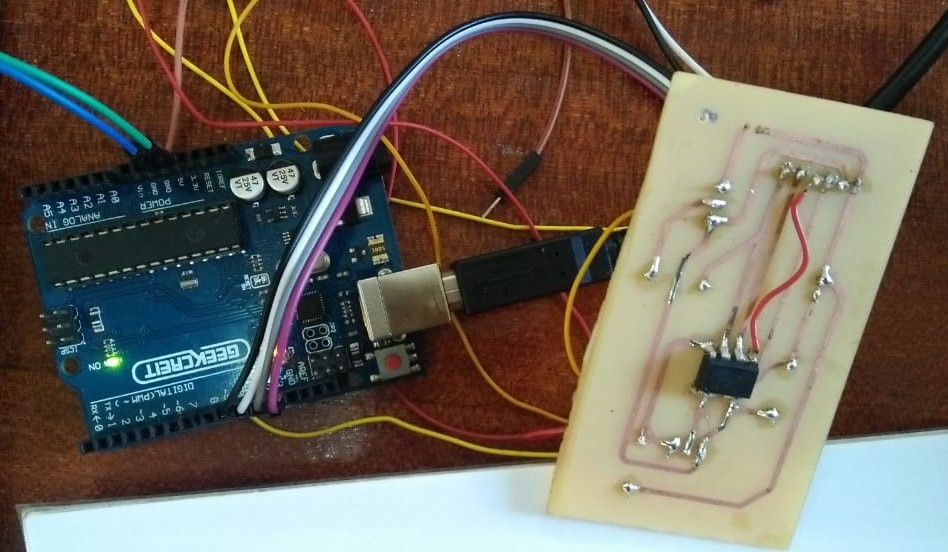
After working on my board i then Solde
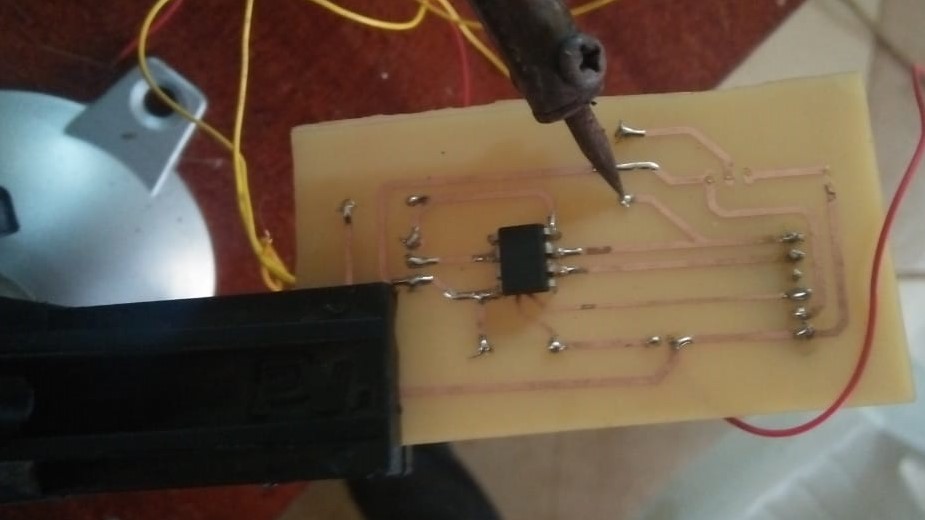
After testing my board using multimeter, everything was fine awaiting for programming
/Variables for PIR Sensor
#define pirPin A3
int PIRValue = 0;
//Variables and constants for LDR
int sensorPin = A2; // select the input pin for LDR
int sensorValue = 0; // variable to store the value coming from the sensor
int threshold = 400;//Threshold for the ldr sensor
//Variables for the LED pins
int ledStrip = 7
;
void setup() {
pinMode(pirPin, INPUT);
}
void loop() {
sensorValue = analogRead(sensorPin); // read the value from the sensor
if (sensorValue >= threshold){
analogWrite(ledStrip, 0);
}
else {
delay(1000);
// wait for a sec
ond
if(digitalRead(pirPin) == HIGH) {
analogWrite(ledStrip, 255);
delay(50);
}
else if(digitalRead(pirPin) == LOW) {
analogWrite(ledStrip, 0);
delay(50)
;
}
}
delay(1000);
}
Download files