probe an input device's analog levels and digital signals
I used my light sensor to measure the analog levels and digital signals.
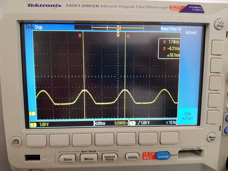
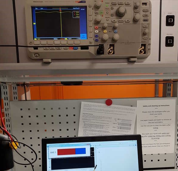
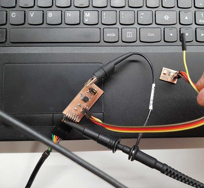
We used oscilloscope to measure analog level from the sensor and digital signals from the FTDI cable.
More about the group work is in the
We used oscilloscope to measure analog signal coming from a sensor
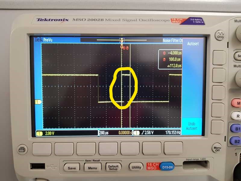
Measured output from attiny45, in rx line at FTDI connector. Now it is clearly ones and zeroes. We could see the signal rate from the oscilloscope it was 112 µs.
We can see that the signal starts with 0 and then the actual data sending begins.
measure something: add a sensor to a microcontroller board
that you have designed and read it
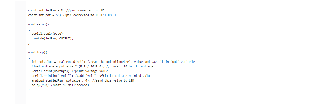
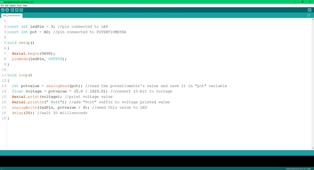
For this week assignment I’m going to use a Photoresistor sensor, which is possibly one of the sensor I am going to use in my final project.
First I want to see how it works and if it really is what I need for my project. So I am going to test it and will see.
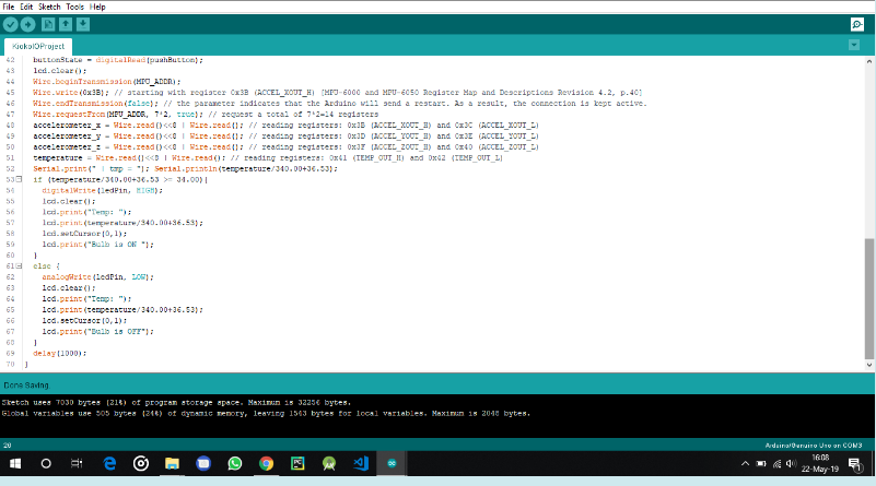
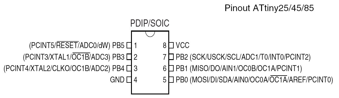
ATtiny 45 has 4K flash, 6 I/O's, 256 bytes of RAM and 256 bytes of EEPROM.
It has an internal oscillator which runs 8 or 16MHz.
ATtiny 45 when compared to an Arduino Uno, it is so much cheaper.
It is a suitable choice for small projects.
I will be using arduino as the isp and use Arduino IDE to program the ATtiny
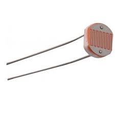
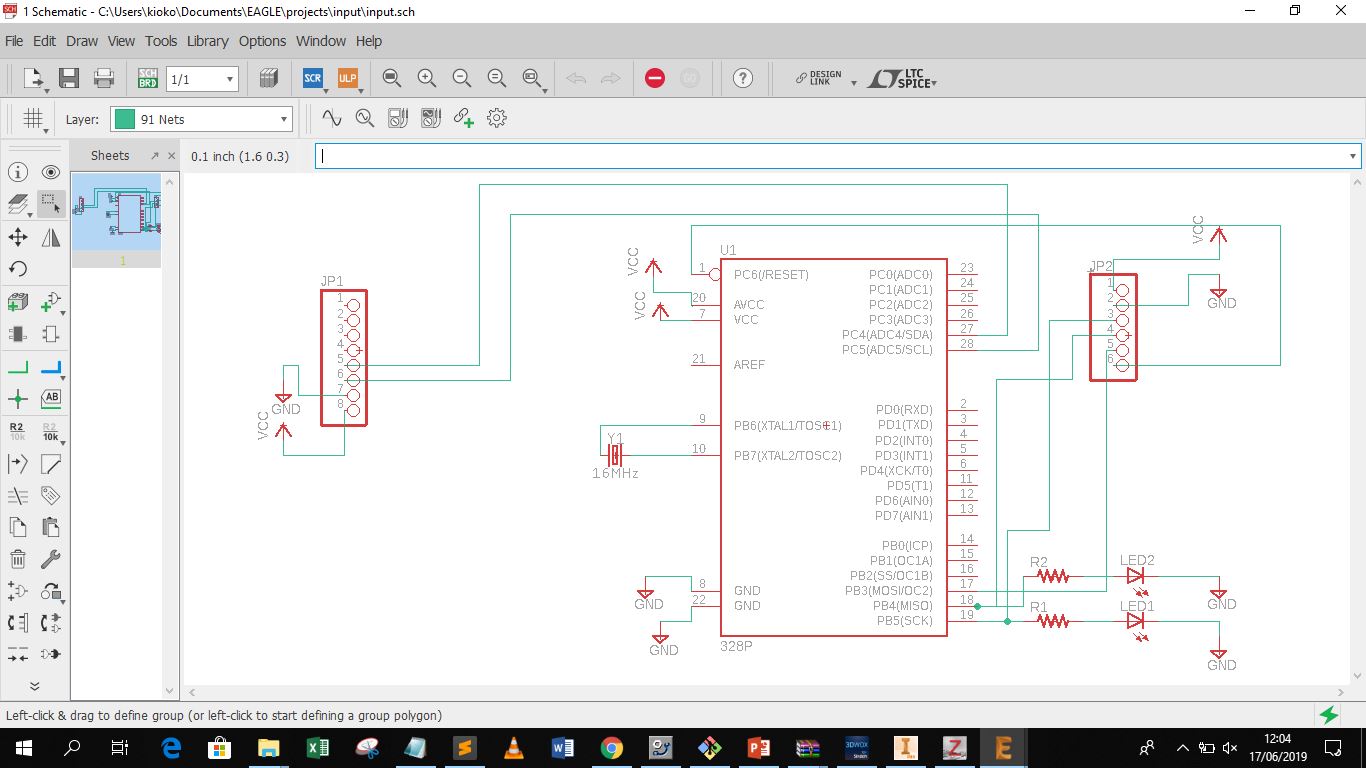
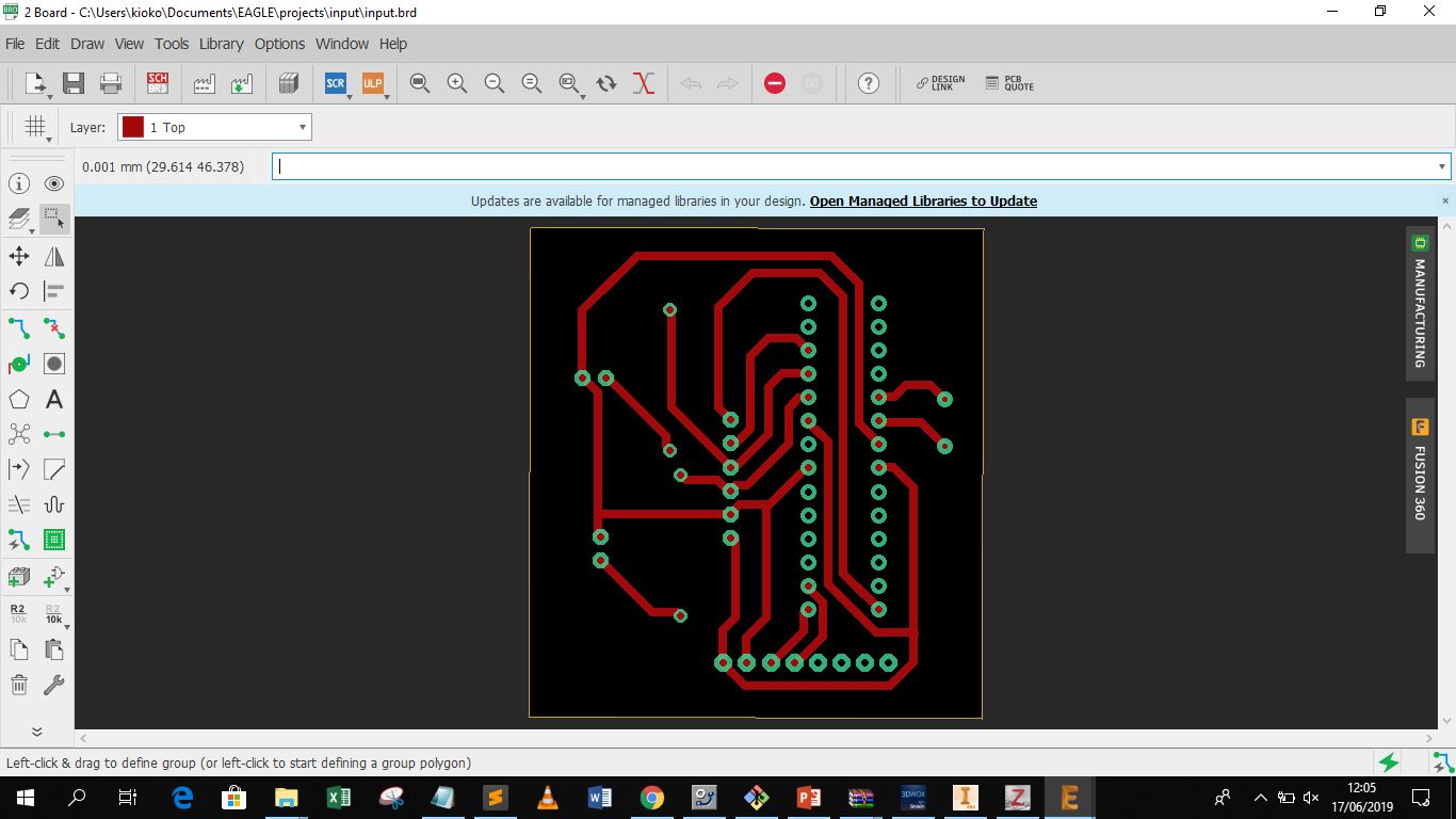
Photo resistor or light dependent resistor, is a light controlled variable resistor,
The resistance decreases with incresing incident light intensity. We are going to connect up the circuit as below.
I will read in the value of the ldr and program it such that when we cover the ldr, the led will turn on. This is to simulate a night light circuit.
I am trying to pogram it such that when the surrounding is Dark, the LED is on. When there is light, it will dim.
const int ledPin = 3; //physical pin 2
const int ldr = A2; //physical pin 3
void setup() { // initialize the LED pin as an output:
pinMode(ledPin, OUTPUT);
pinMode(ldr,INPUT);
}
void loop() {
int v = analogRead(ldr);
if(v < 100)
{
digitalWrite(ledPin,HIGH); //Turn on LED
}
else
{
digitalWrite(ledPin,LOW); //Turn off LED
}
}
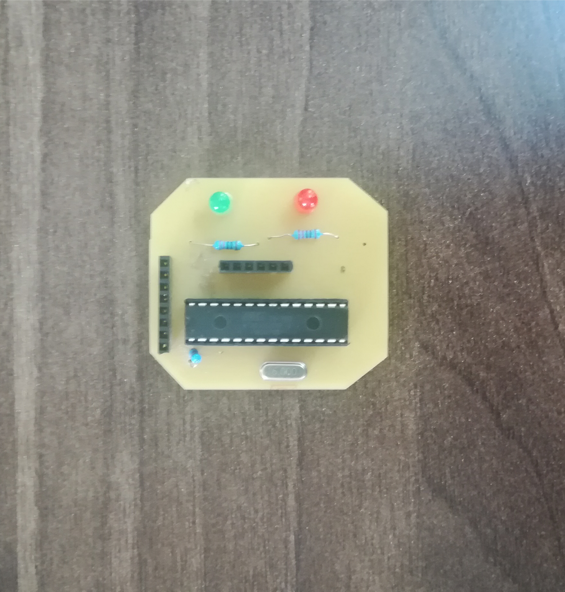
After burned the bootloader on my board, I write the following code and I uploaded it on my board (using the programmer).