Week 10. Molding and Casting
10. Molding and Casting
Assignment
Group assignment:
“Review the safety data sheets for each of your molding and casting materials
Make and compare test casts with each of them”
Individual assignment:
“Design a 3D mould around the stock and tooling that you’ll be using, machine it, and use it to cast parts.”
Files
Desing files for wax mold in Fusion360
STL of watchmold
G-code Finishing Toolpath
G-code Roughing Toolpath
V3D file for ShopBot
Hardware
Shopbot
mills
vacuum pump
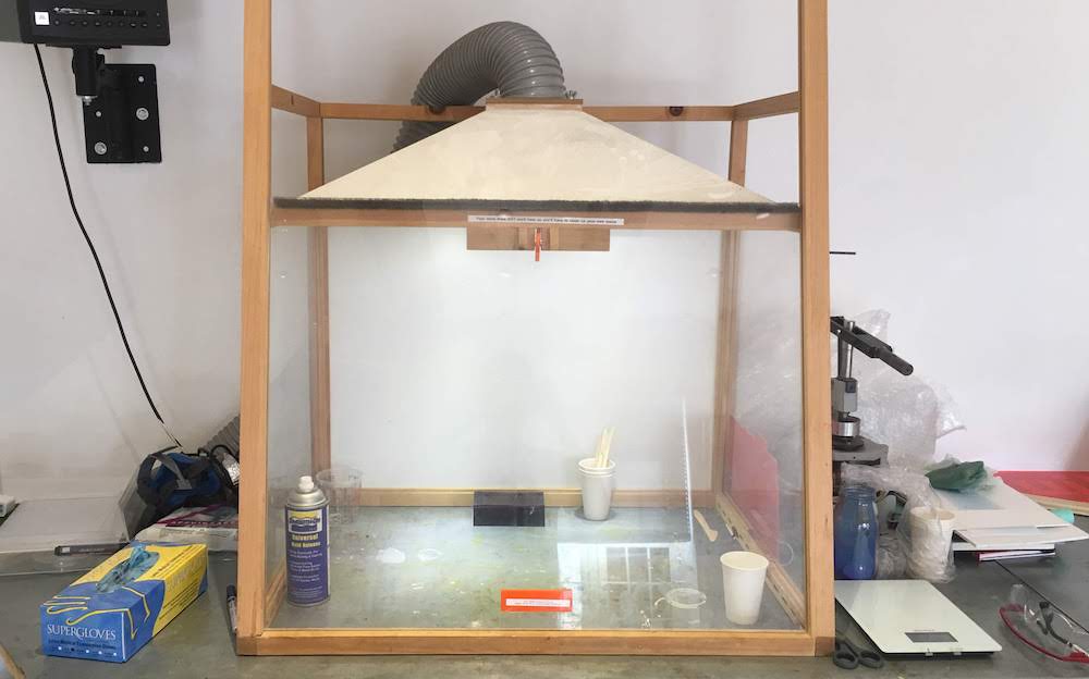
suction area
gloves
safety glasses
cups
stirring equipment
universal mold release
Software
Fusion360 (for designing the mold)
PartWorks 3D (software for translating mold design to G-code for the Shopbot)
Shopbot controll software (for sending the G-code to the Shopbot)
Before you start
- Do not use materials that are not for home usage
- Read the Safety DataSheets (SDS)
- Provide for adequate ventilation, especially for urithane and epoxy.
- Wear gloves and glasses as protection
- Do not despose pure resins in the trash, mix them before disposing. Or bring them to the “mileu-straat”.
- If you do not know what you are doing get help.
Group Assignment: Reviewing Safety Data Sheets
For our group assingmend, each of the members looked at one material in detail and later we discussed these materials together.
I looked at the Vytaflex 50. Urethane Rubber Compound.
It is a Mix ratio of 1A:1B by Volume. Indicating you need half of compound A and half of compound B, and determine this by volume.
It has a Pot life of 60 minutes. The Pot life can be confusing, but it is the time you have to work with your material including mixing and pooring.
As the website Permabond describes it:
“Some people call the pot life ‘working life or working time’ meaning how long you can work with the adhesive before it starts setting hard.
This should not be confused with working strength.”
“Open time is very similar to pot life, it means the time you have from the point of mixing or activating the adhesive, applying it, assembling the parts and closing the joint.”
Vytaflex has a Cure Time of 16 hours. The Curetime stands for how long it takes to harden.
Beware that both Pot life and Cure Time are at a constant temperature of 23 degrees centigrade.
Part A
Part A, SDS No 614A.
This compound is dangerous!
Acute toxicity:
- oral: category 4
- demal: category 4
- inhalation: category 4
- skin irritation: category 2
- eye irritation: category 2A
- specific target organ toxicity-single exposure: category 3 (respiratory)
It is harmfull if inhaled, swallowed, and in contact with skin. It causes skin irritation, serious eye irritation.
Finally it may cause respiration irritation. (I am wondering for how long, a day? life?)
As prevention precautions you need to avoid breathing it (obviously), wash with soap and water thorougly after handling, not eating, drinking or smoking when using, wear gloves, clothing, eye and face protection and use outdoors in a well ventilated area.
When reading at section 8 Exposure Controls and Personal protection we see we do not really need respiratory pretection if we use it in a well ventilated area, and do not have to wear protective clothing, further we should wear liquid-tight gloves and safety glasses.
And after usage wash our hands thorougly.
Part B
Part B, SDS no 419B, looks to be as safe as soap.
You should NOT eat or drink it, and wearing of gloves and protective eyewear is adviced, but that is it.
If you get it in your eyes you should flush with plenty of water, and only if irritation persist seek medical attention.
Still be carefull with it.
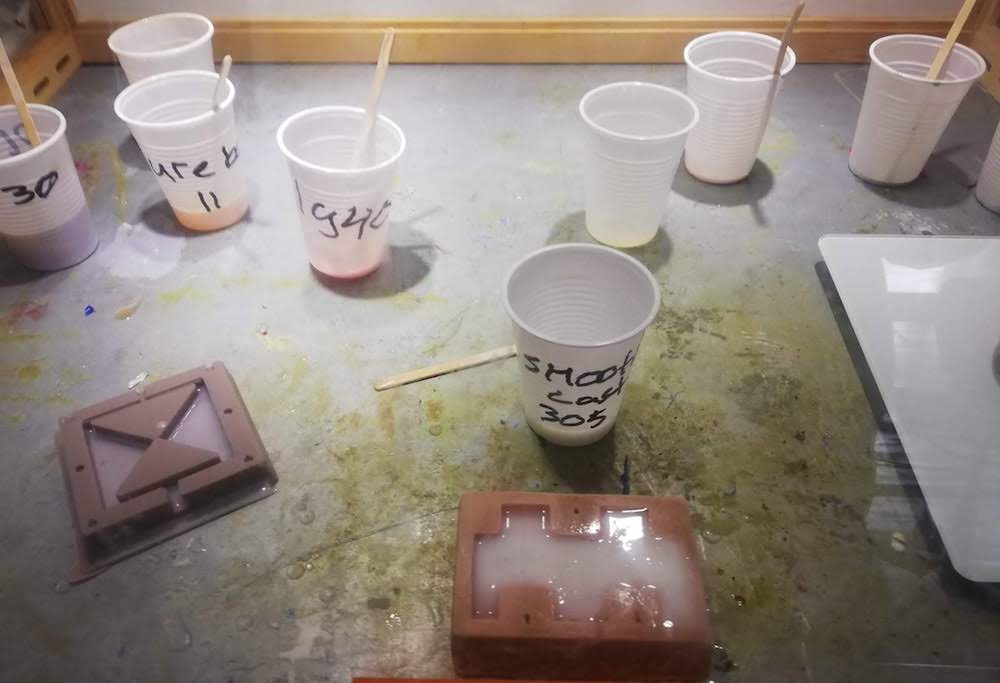
Comparing together and casting
We poored different types of material, and compared their curing time and pot life.
There was not a big amount of difference between the materials in those aspects.
We did saw that some materials where highly toxic before mixing, while others can even be touched by hand.
Still this exercise really showed me that you should always try to be as safe with these materials as you can.
Next we mixed the different materials in cups.
We noticed that some materials give more bubbles than others.
After letting them cure, we saw some materials were more transparentish and others solid, while almost all were transparent when we started mixing.
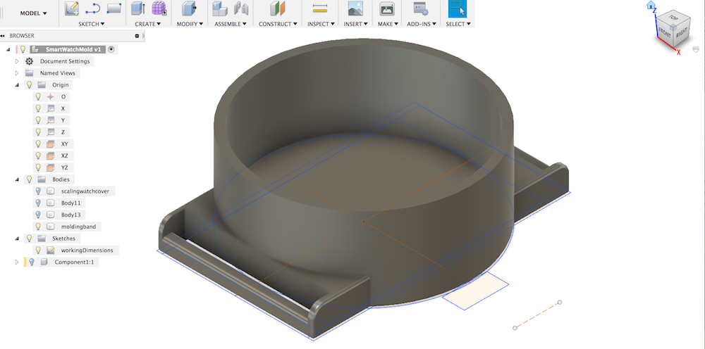
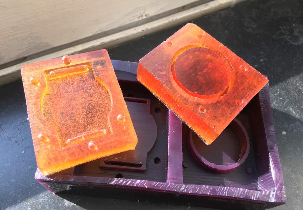
Making a mold
For this exercise we will be creating a 4 part mold:
- We start with a mold design in Fusion36
- First create your design as you would create a 3D design of a part in Fusion360.
But take into account your possibilities and limitations of your chosen tools and materials.
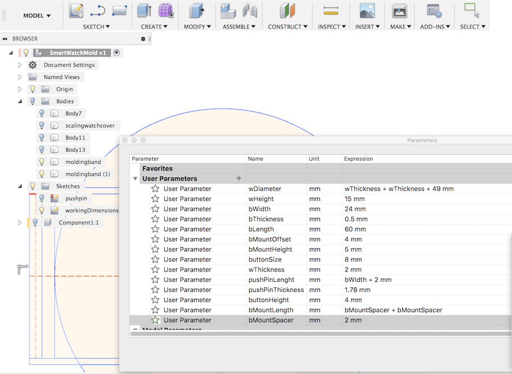
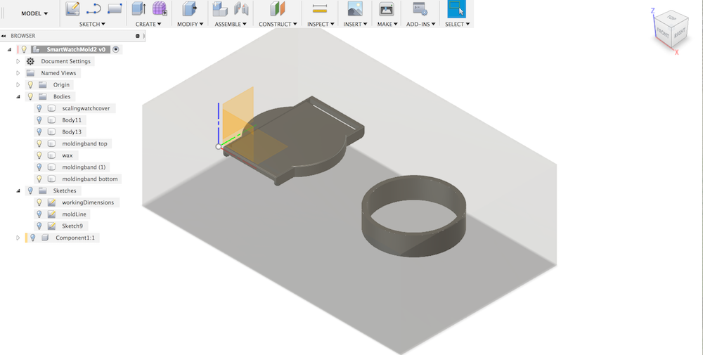
We took our 3D design of our watch case and modified the design to fit the chosen materials. For example the slots for the armband were made bigger to be able to be milled using a 3mm mill.
Also we simplified the design (less curves and less slopes) to be able to speed up the milling.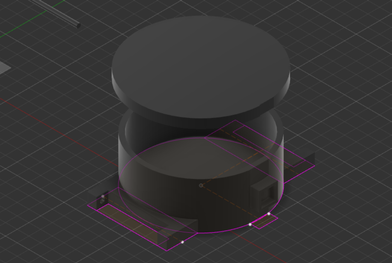
- Next create your wax as an object, this helps you to see if your design fits your limitations in size.
Further refine your design if needed. We decided to reduce the size of the band. This was easy to do in Fusion360 because we used parametric design.
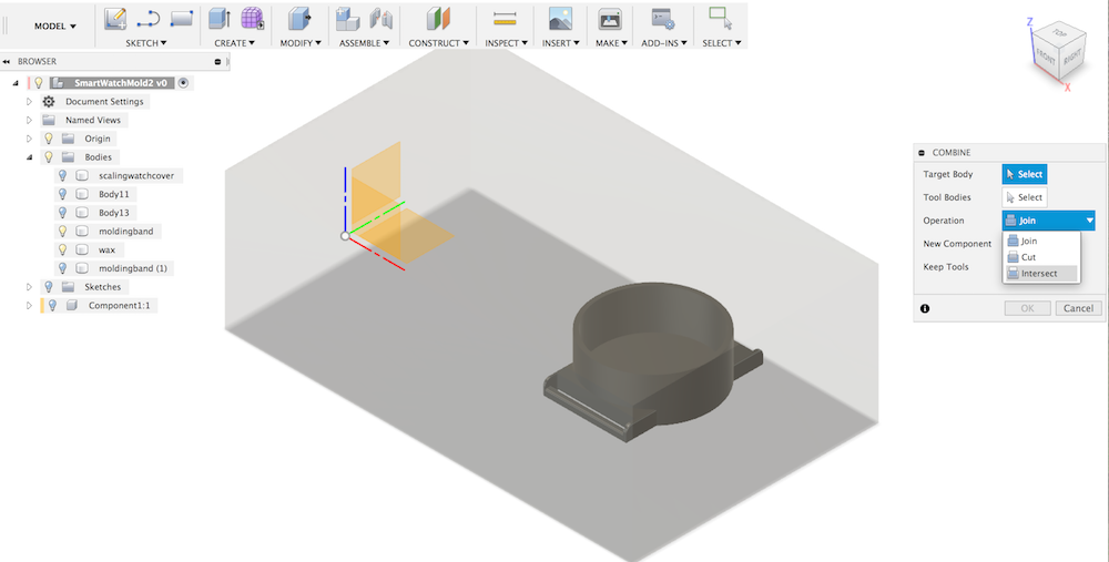
- We are creating a two part mold. So we need to decide where to split our mold.
Take into account the shapes of your design and how the CNC mill is able to replicate this design.
With our watch case for example we have a hollow cilinder and a sloped flat surface. For the mill to be able to create the hollow cilinder we need to have that part exposed.
Also the sloped surfaces would be nice to have. So our most optimal position for our wax mold is to place it near the bottom of our watch case desing. - Draw a line and use this to split your object using the “Split body” function
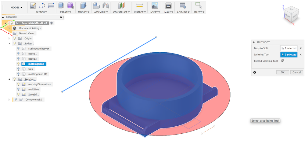
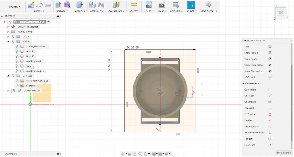
- Next draw a plane at the split. This plane will be your size of your flexible mold.
Make the plane big enough to enclose your design, with a margin of more than 5mm (our rough cut mill)
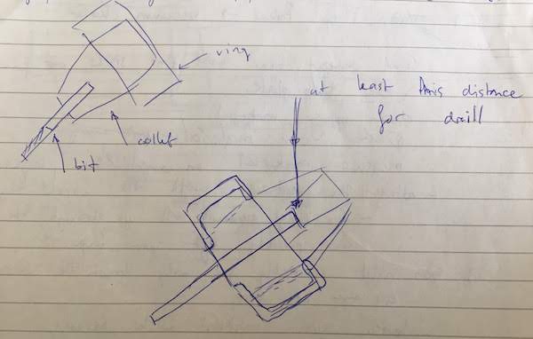
- Also now it the time to determine how you want your two halfs to connect.
I tried connector stubs, but I would advise to create a special connecter ridge.
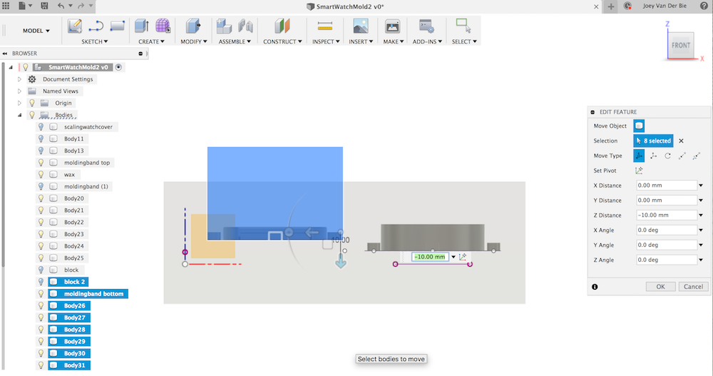
The advantage of a ridge over stubs is that it not only allows an easy fit of both of your halfs, but also prevents the casting material to leak out. - Rotate one half of your object 180 degrees over the Z-axis and place both objects in the wax.
You now have the top of one object and the bottom your other object pointing upwards. - Also copy and rotate your plane with your object.
You now have at both objects the same size and position plane.
- After creating your connectors, also cut them in half and rotate on half 180 degrees.
Substract at one side your connectors from your wax and let the other side of your connectors stick out and join it to your wax.
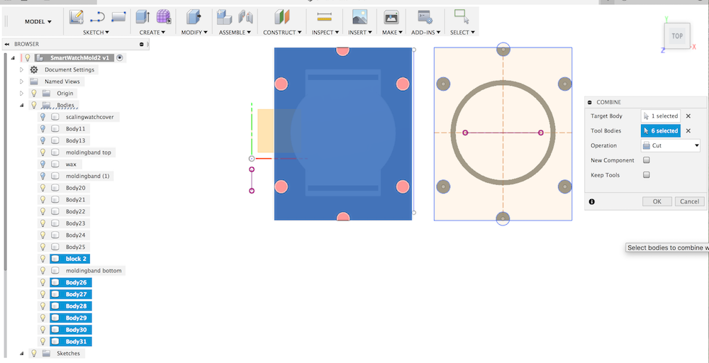
- Extract your plane at both sides and extract them from your wax.
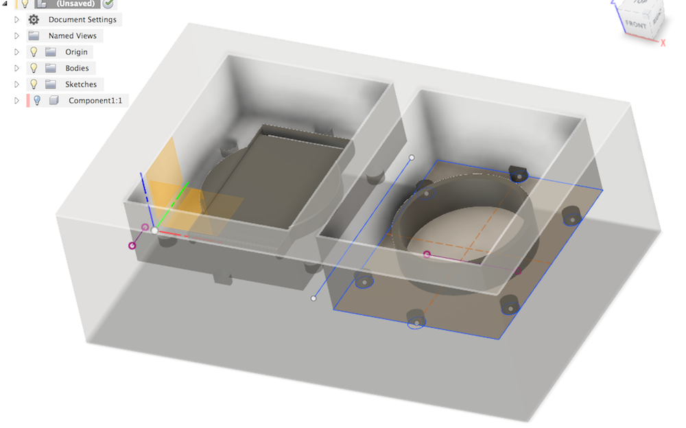
- Now determine where to put your pooring hole and air holes and include them in your design (I did not do this, but you should really do this!)
- Last check your design for errors and correct where needed.
Join all the surfaces as one object, and export that object as an STL.
Machining a mold from wax
Before your start Safety first!
- NO long hair, long sleeves or lose ropes ect! You do not want to get stuck in the machine.
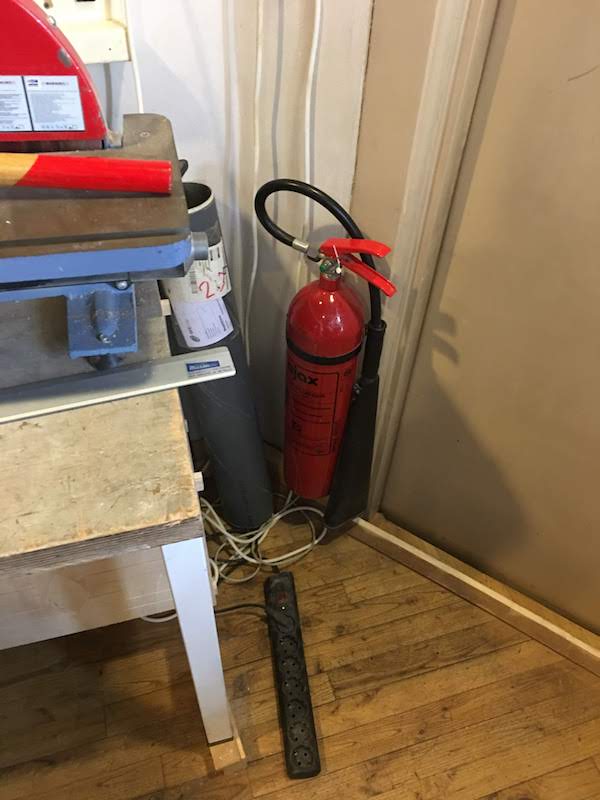
- Know what to do in case of FIRE! Know where the fire extinguisers are.
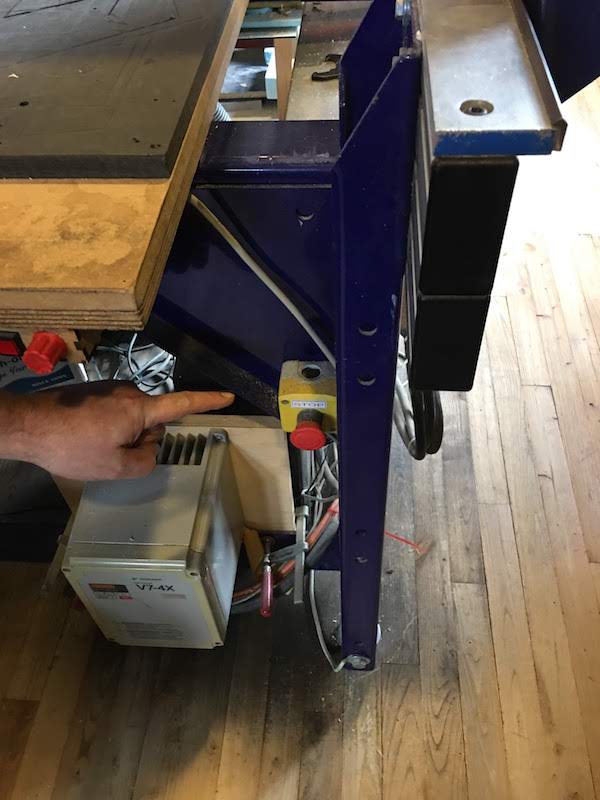
In case of even one spark: turn OFF the spindle and machine and check if you did not cause a fire in the vacuum cleaner. - Know where the emergency stop is.
- Never touch the machine when powered, always first turn the power off.
- When you stop the cutting process always lift the spindle and turn of the spindle to prevent fire!
- When the machine is on you never leave the device, but stay to monitor your progress.
- Check if your material can be cut using the shopbot. If you do not know the precise contents of your material you are not allowed to cut it.
- If you do not know what you are doing, ask somebody to help.
We will be creating a wax mold using our 3D mold design and the CNC-mill.
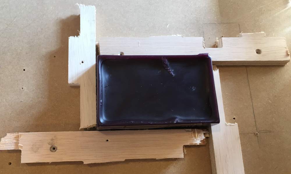
In this example you see a malformed piece of wax, make sure you use a piece of wax with a flat top.
You can create a flat top by milling the top flat, or making it flat by hand.
We will be using a two step milling process:
- Roughing toolpath: this is the rough cut of our design, using a 5mm end mill and big stepover
- Finishing toolpath: this is a detailed cut of our design, using a 3mm end mill and a small stepover Protip: use the flat-end mills as default and the round-end mills for curved surfaced that cannot be milled with a flat-end mill
Steps:
-
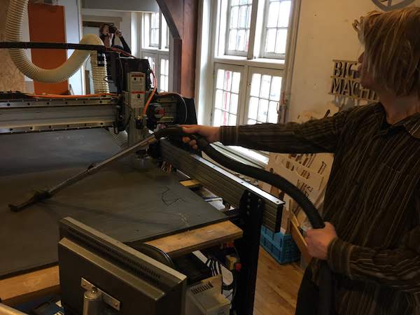
Know knowing what to do in case of fire, and how to keep everything save we can start touching the Shopbot.
Make sure the device is turned OFF.
Next clean the sacrificial layer. In our case it is this nice black layer that we can use to fix our material on and that is nice and flat.
Clean the sacrificial layer by vacuuming all the dust and residu material, and by sanding away imperfections from screws.
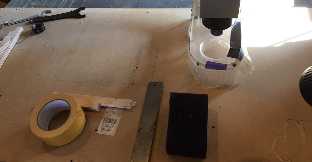
- After cleaning place your material.
Place your material on the sacrificial layer and attach it using double sided table.
Make sure your wax is in line the the X and Y-axis. I used a 90 degress measurement tool to keep my piece of wax inline. Next place pieces of wood around your material to keep it in place.
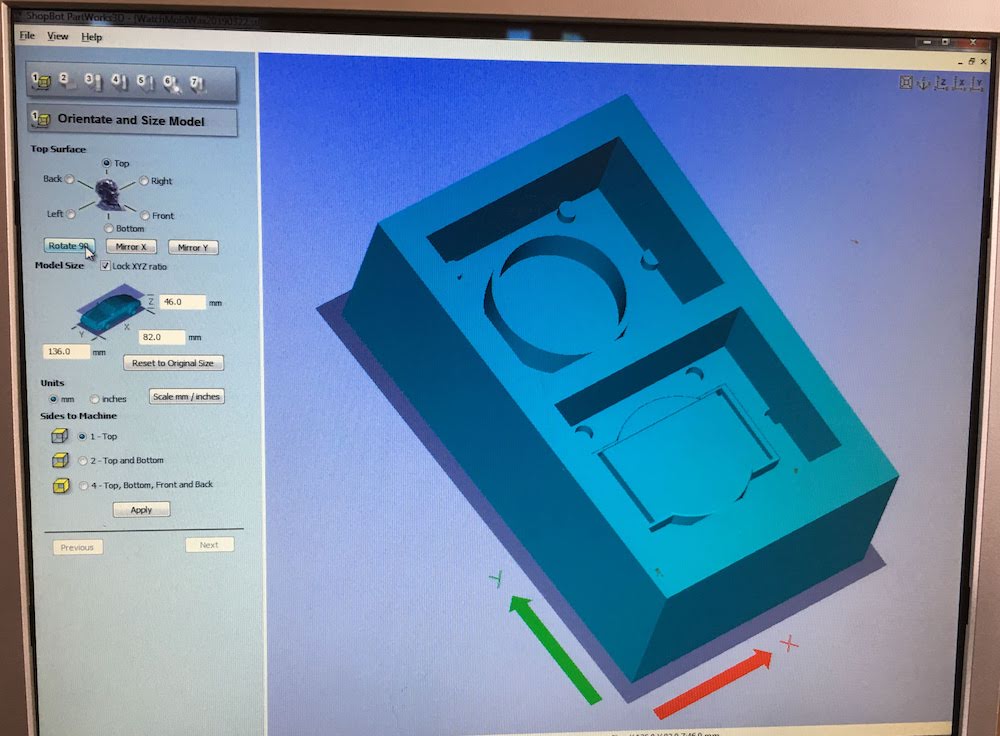
- Import your design in PartWorks 3D. And check if your dimensions are correct and determine the orientation.
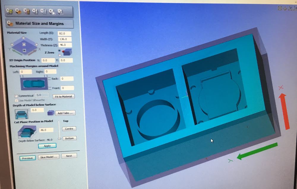
- Set where you want to calibrate your Z-axis. I advice to use one of the top corners, since that will stay the same during milling.
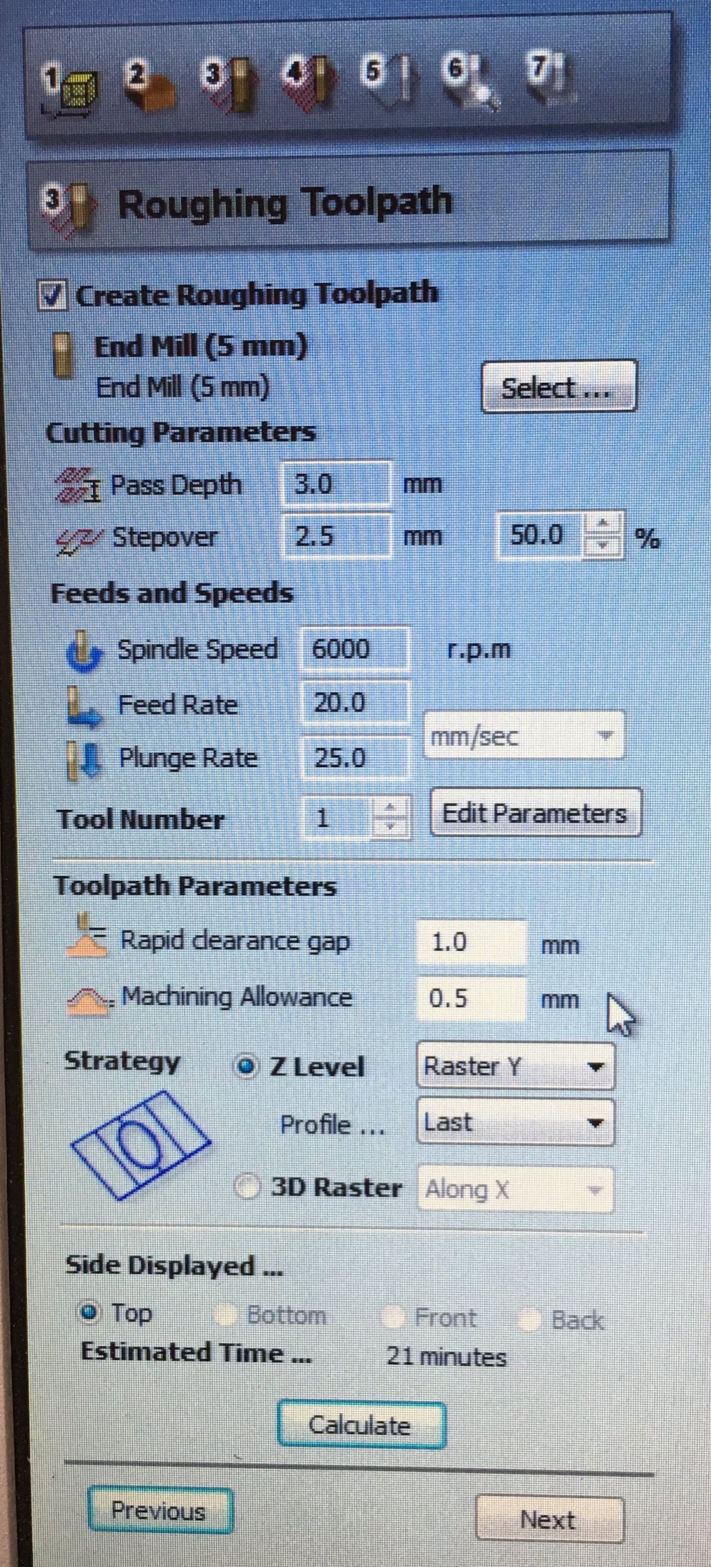
- Next determine your roughing and finishing toolpath.
For roughing toolpath I advice:
- 5 mm mill
- passdepth: 3.0 mm
- stepover: 2,5 mm
- spindle speed: 6000
- feedrate: 20 mm/s
- plungerate: 25 mm/s
- rapid clearance gap: 1 mm
- machining allowence: 0.5 mm
- strategy: Z-level Raster Y
 .
.
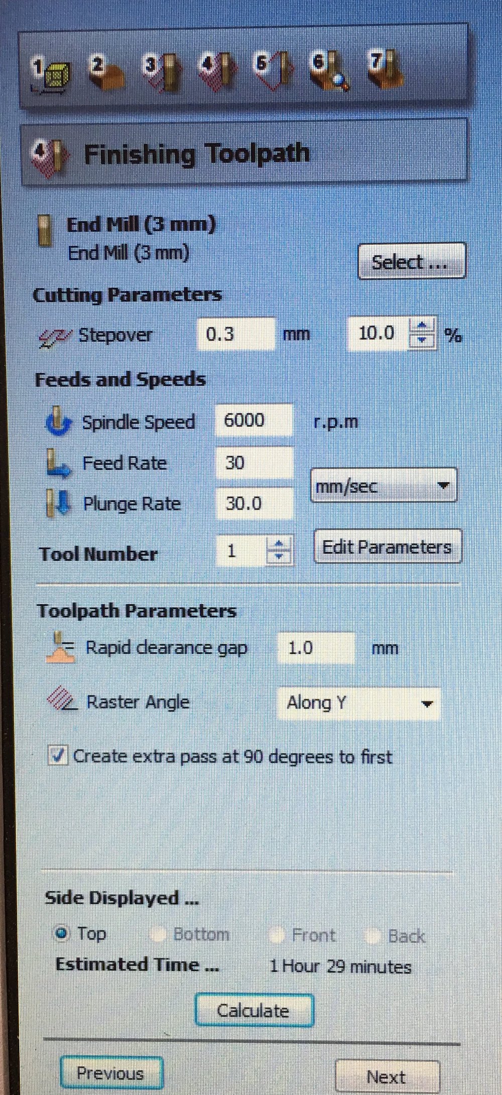
For finishing toolpath I advice: - 3 mm mill
- passdepth: 3.0 mm
- stepover: 0.3 mm
- spindle speed: 6000
- feedrate: 30 mm/s
- plungerate: 30 mm/s
- raster angle: along Y
- and create extra pass at 90 degrees to first
 .
.
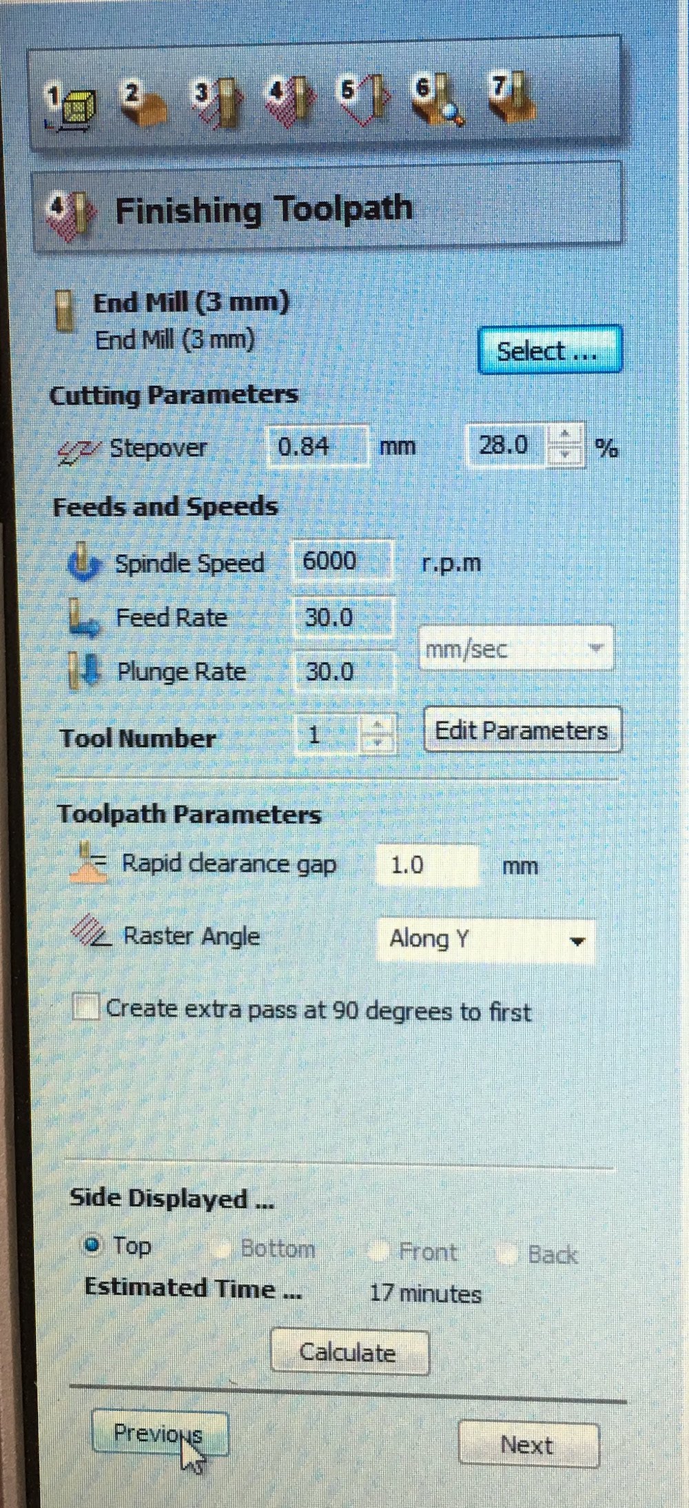
When you are experiencing time constrains you can offcourse change these parameters, but they will influence the detail of your eventual design. I had to limit my design and unchecked the extra pass and increate my stepovertime.
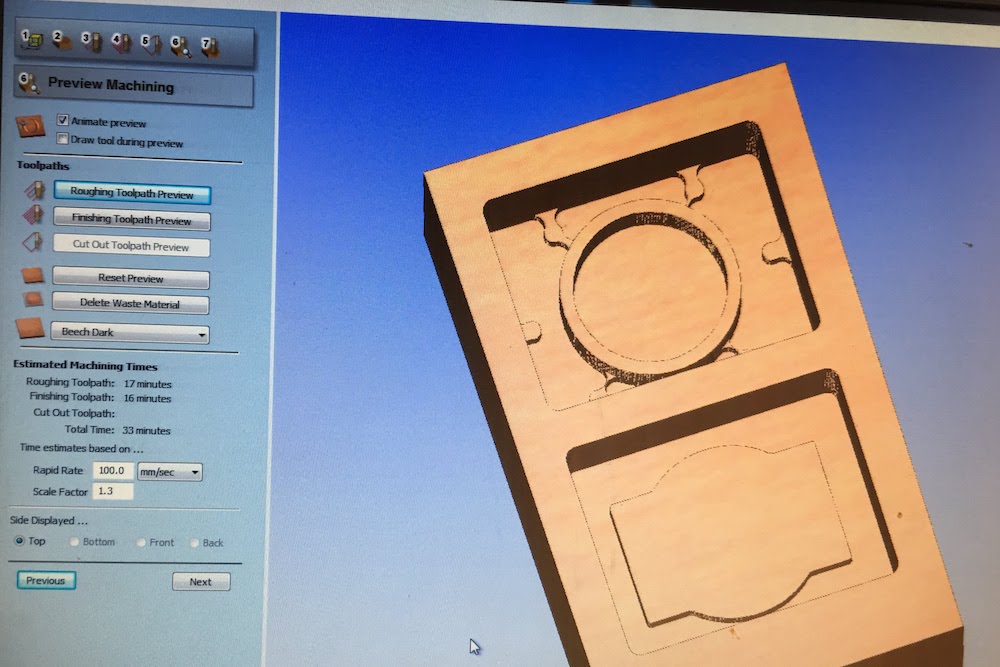
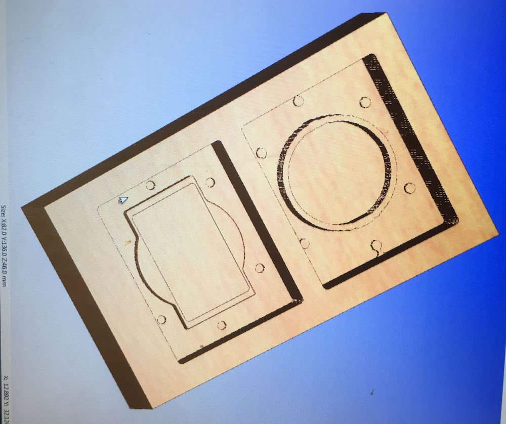
- During the creating of our toolpaths check the simulation to see if everything turns out the way it should be.
- Export your toolpath.
- Place your mill, see the section (Re)Placing mill
- Turn on the mill, (NOT the spindle), and NOT the vacuum. and launch the Shopboth milling software
- Calibrate X, Y, Z axis (Z axis at the corner of the material) (see calibration section for details)
- Load your roughing toolpath
Turn the spindle ON at 6000 rpm. and start milling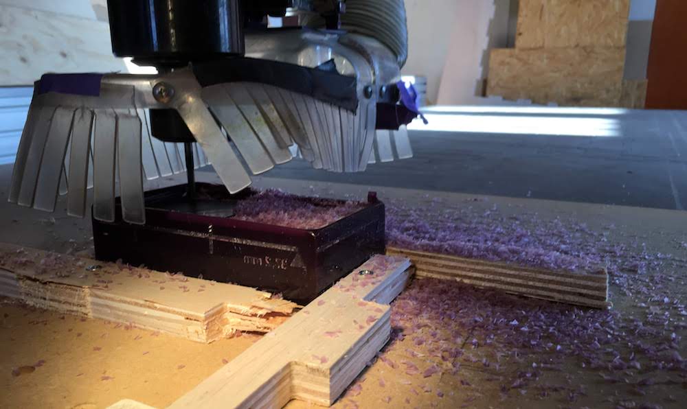
- After the roughing toolpath is finished turn OFF the spindle.
Move the mill out of the way and clean your table and recycle your waste. - Replace the 5 mm mill with the 3 mm mill and recalibrate your Z-axis at the 0,0 position.
- After recalibrating load your finishing toolpath
turn the spindle ON at 6000 rpm
and start milling - After the finishing toolpath is finished
Turn OFF the spindle Move the mill out of the way and turn it OFF
Clean your table and recycle your waste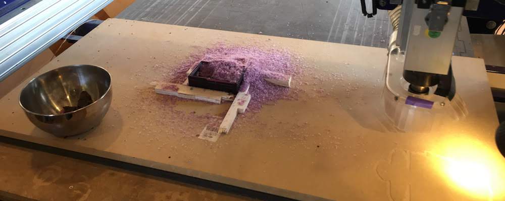
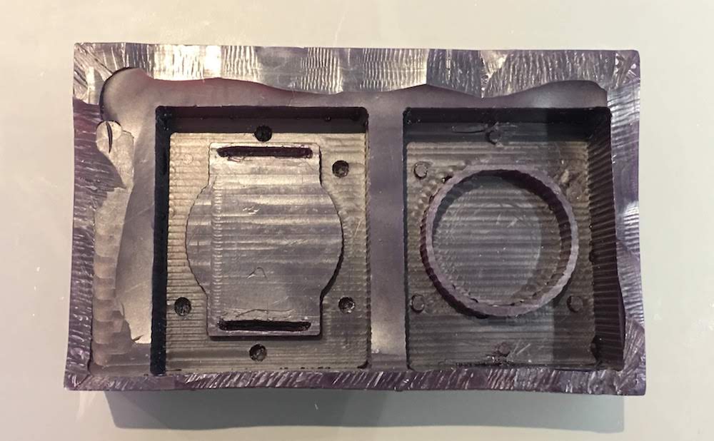
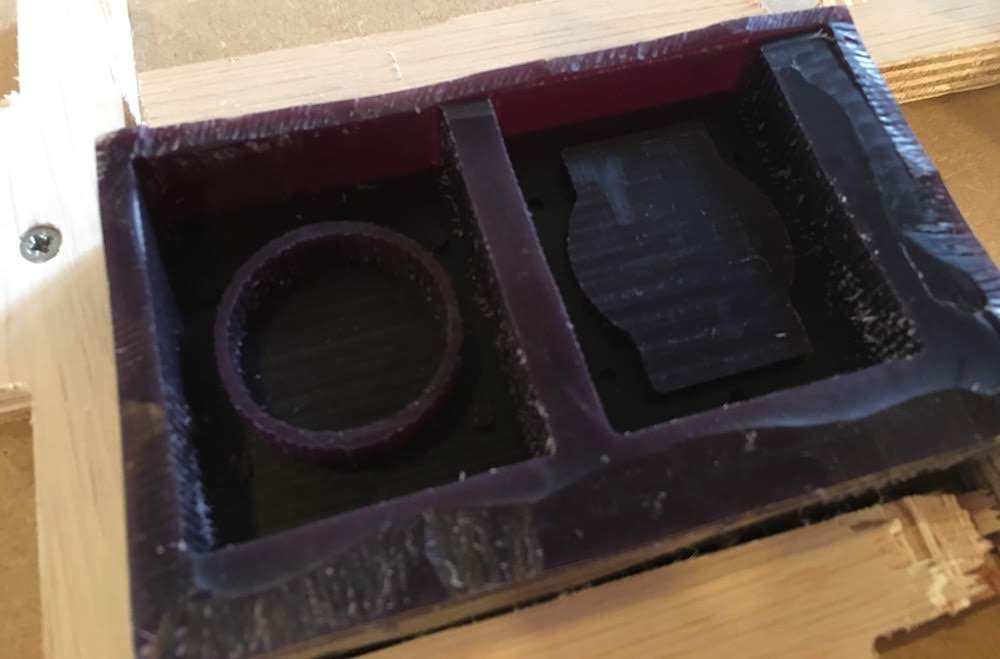
Check your wax for faults before removing.
(for example I was missing some details that not fit the 3mm mill, see also my fails “Wax mold missing details”)
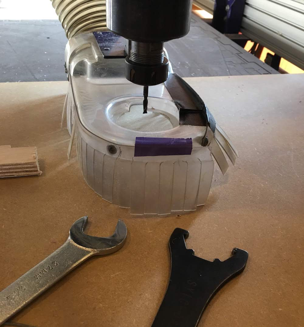
(Re)Placing mill
For (re)placing a mill. First make sure the Shopbot is OFF and the spindle is OFF, and the key is not machine.
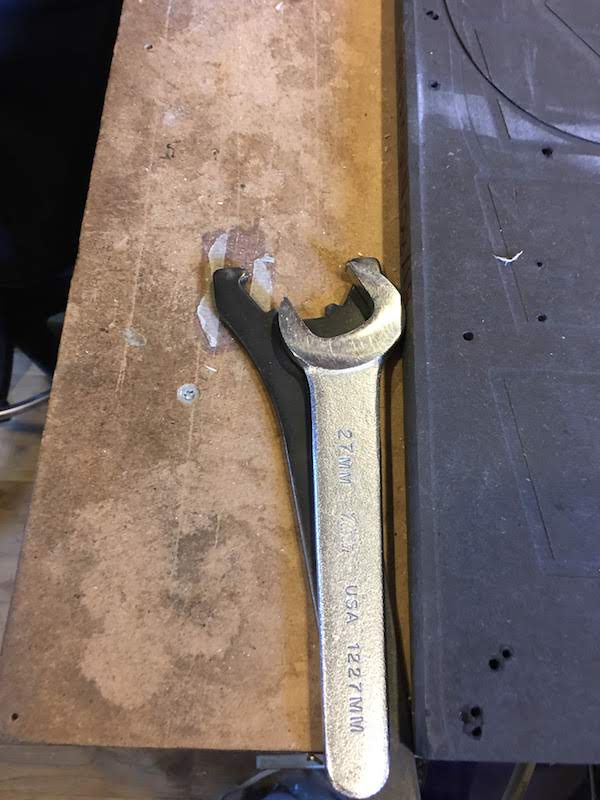
Next get the tools for replacing the mill.
Move the vacuum scirt up (there is a small screw at the back of the spindle) and remove the old mill with yor tools.
Find the mill you want to use and select the fitting collet, it should fit tight when only holding with your fingers.
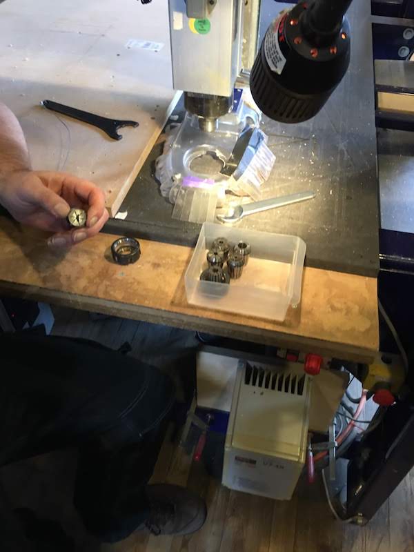
Place the mill in the collect and the collet in the ring. Make sure the mill is placed as in the image.
Tighten the mill to the spindle monkey tight, but make sure it is not to lose, we do not want to have a flying mill.
Last check if your mill is in straight and move the scirt down.
Calibrating
- Place your material and attatch it to the sacrificial layer
- Start the Shopbot and the Shopbot controll software
- Select the option XY icon with the arrows in the software. The Shopbot will now move to its default X and Y 0.
- Move the Shopbot to the new start position. You set a X,Y 0 in your PartWorks software, most of the times this is the left bottom corner.
Remember that the Y-axis is the short part of the Shopbot, so left bottom is actually right bottom on the picture where you see the mill. - Next selec the Zero X and Y option in the menu.
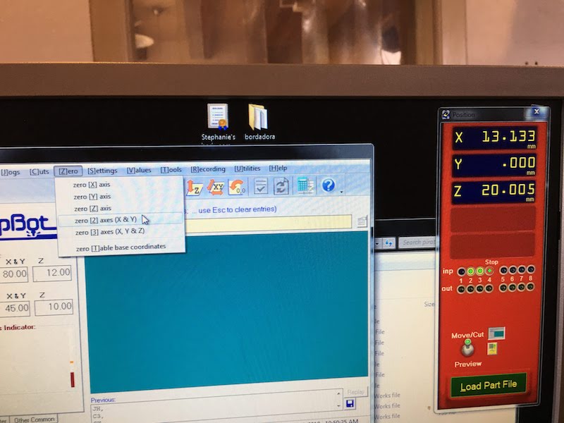
- Place the metal plate under the mill and select the Z icon with the arrows in the software.
You will receive a mesage to place the plate. If you placed the plate press ok. You will get a Z-contact did not clear error, ignore this.
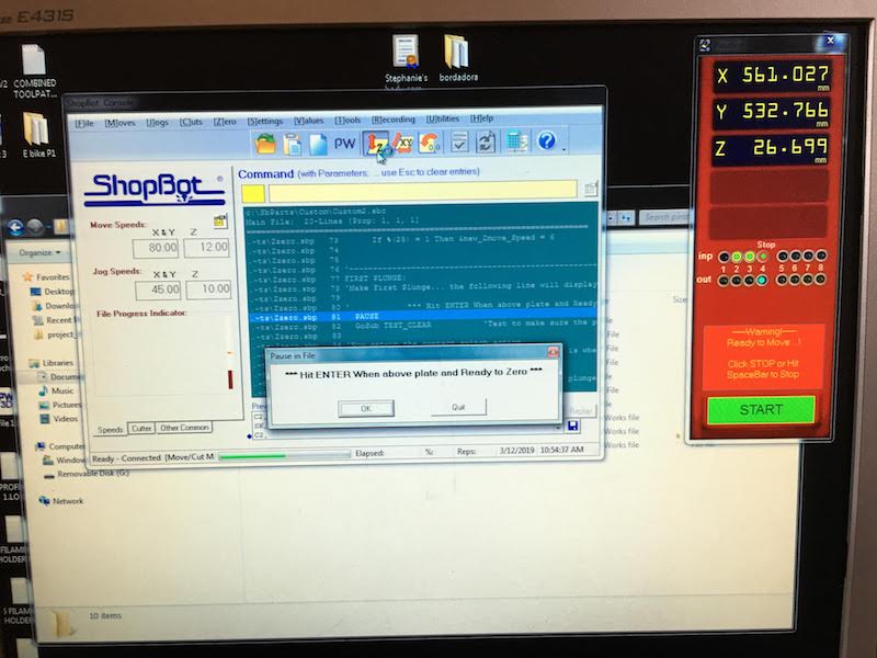
- Next move the mill up and remove the plate. You are now ready to start milling.
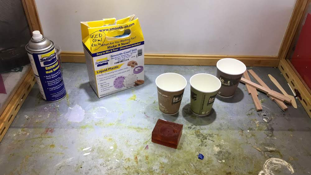
Casting from a wax mold
- Select your material and get your working materials:
- gloves
- safety glasses
- cups
- stirring equipment
- vacuum pump
- suction area
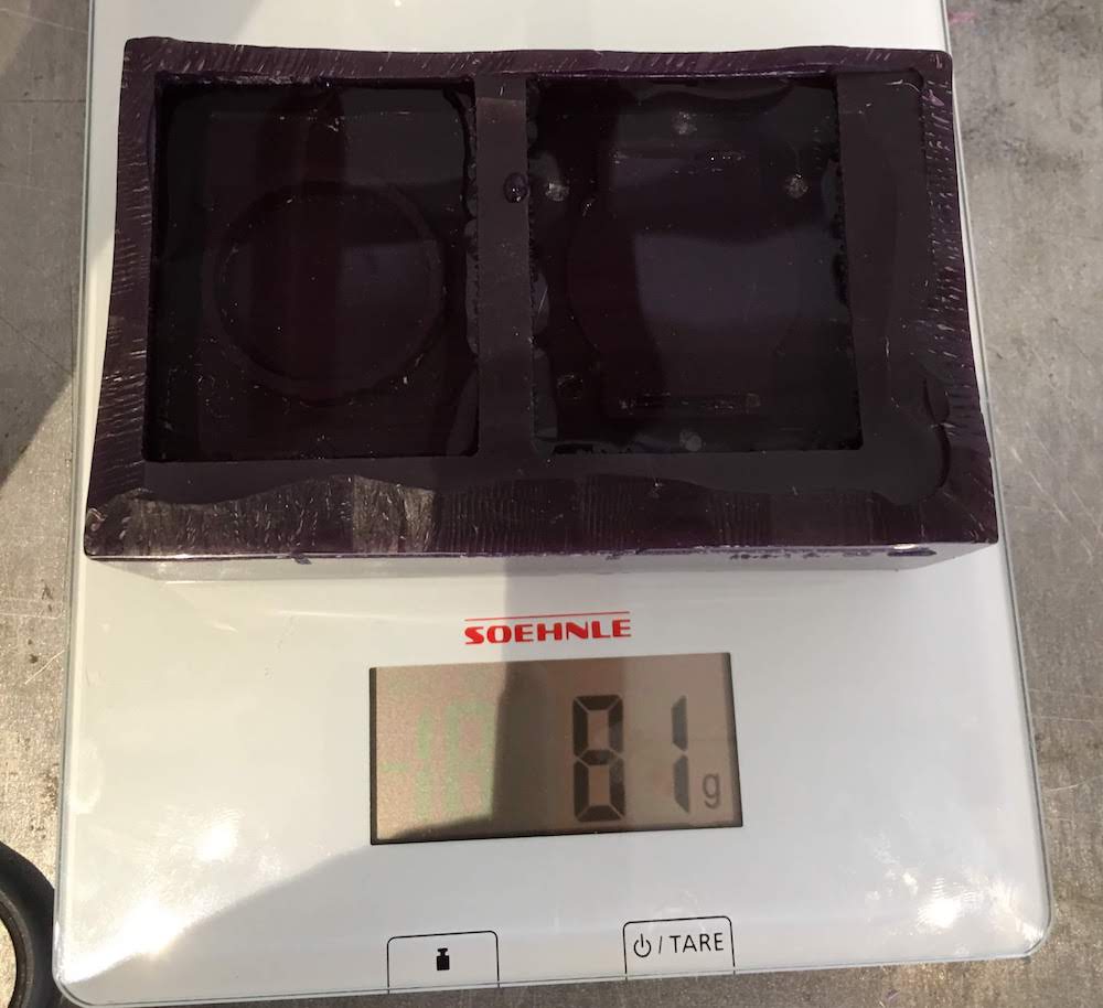
- Determine amount by reading datasheet and using water.
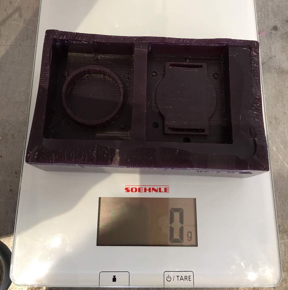
PCM uses amount by volume, meaning equal ratio of part A and B. To determine my amount needed I:- put my mold on the scale and calibrated the scale to from 320 gram to 0
- poored water in my mold and read the amount of water = 81 gram
- put back the water in the cup
- calibrated the scale to a cup (5 gram)
- read the amount of water again = 84 gram. Somehow I managed to create 3 extra gram of water, but thats ok. I will make more material than I need anyway.
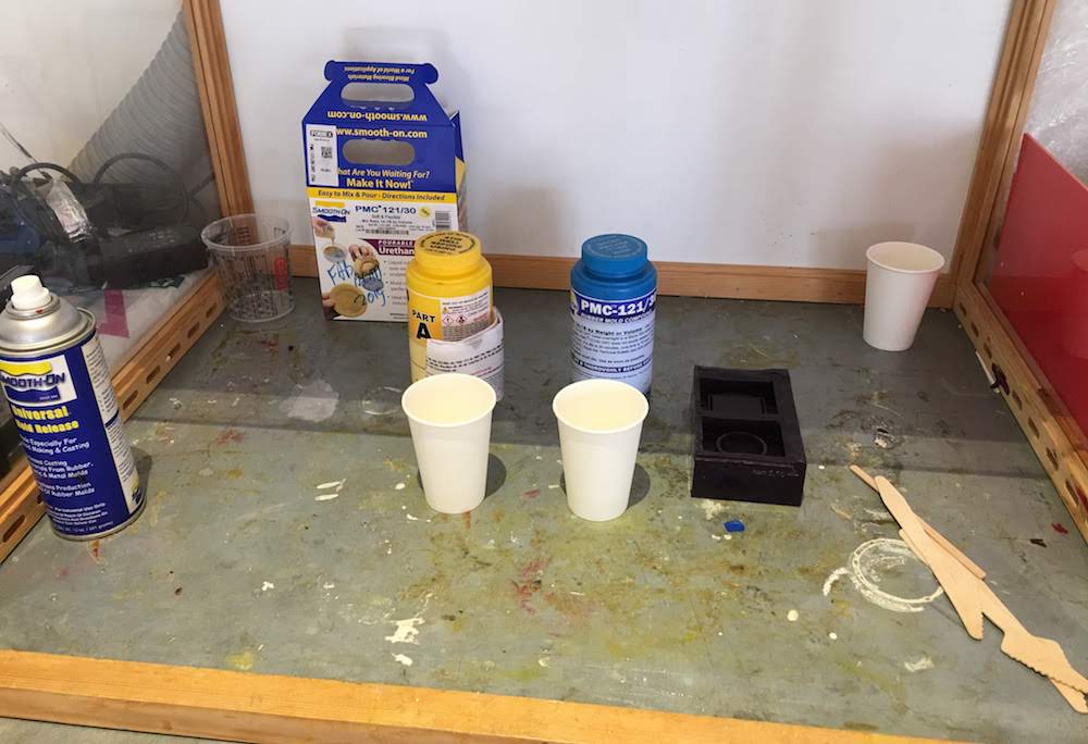
- Next open your material A and B and stir slowly to not make bubbles.
- measure your material in separate cups, in my case half of A and half of B,
and always take a little bit more than you need, this allows you to spoil something and to account with measurement errors.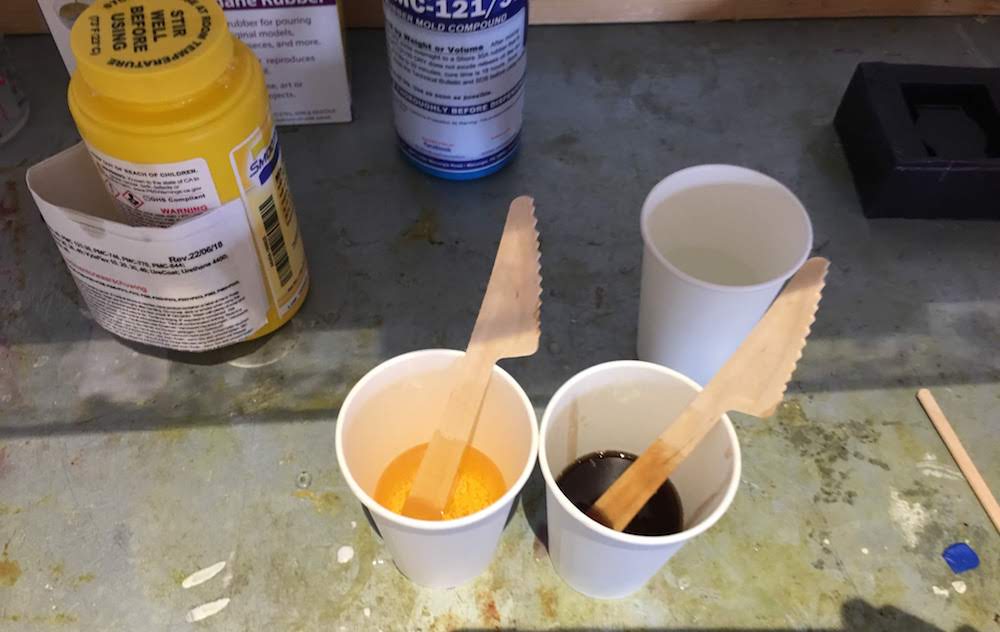
- After measuring, mix your material, slowly poor part A to part B and stir while pooring, try to make as less bubbles as you can.
- If your curing time allows it, put your material in the vacuum pomp at 8 bar preure for a few minutes, I let my PCM stand for 5 minutes.
In the vacuum pomp you see the bubbles come to the top and pop.
After a few minutes of vacuum most bubbles should be to the top.
Turn of the vacuum pomp and slowly open the exit valve to pop the bubbles.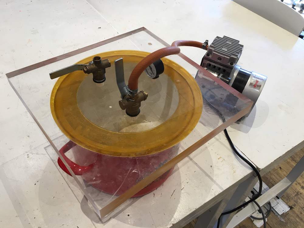
- Poor your material slowly in your mold, if your mold allows it under an angle and poor on one point. Do not poor to fast, you will create new bubbles. I still had many bubbles on the top, so I poored the top part of my material
- After pooring put your cast on a safe place to cure.
I had to let it rest for 16 hours.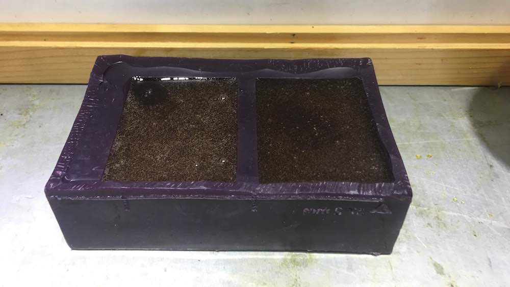
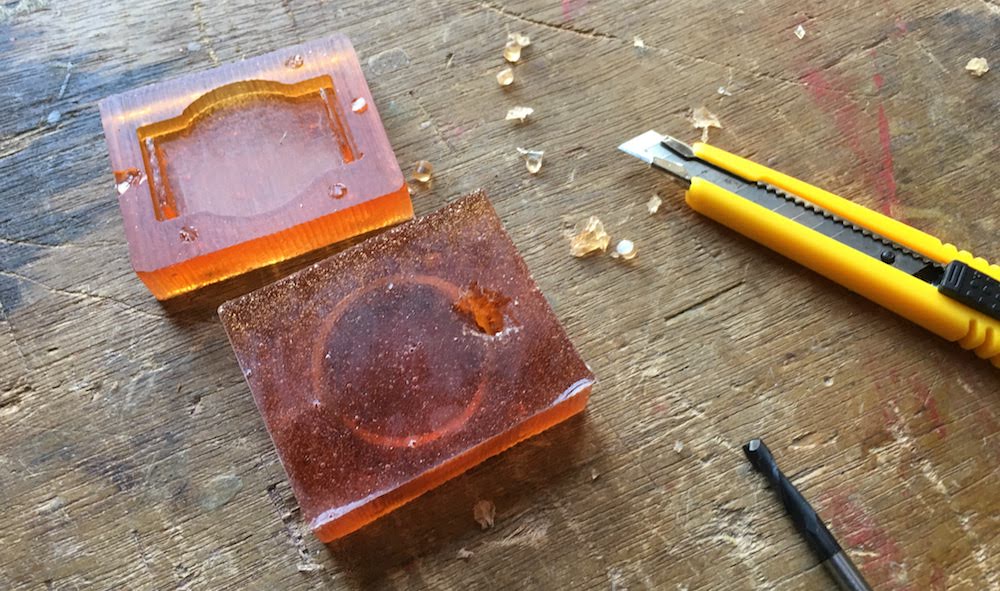
- After resting, carefully remove your cast from your wax. Start at the corners and work your way towards the middle.
Casting from a two part PCM mold
Casting from a two part mold is almost the same as casting from a wax mold.
Only before you can cast you need to prepare your mold defferently.
Also we will in clude jusing universal mold release in this example.
- Select your material and get your working materials:
- gloves
- safety glasses
- cups
- stirring equipment
- vacuum pump
- suction area
- universal mold release
- Determine the amount by reading datasheet and using water.
Smooth-cast uses amount by volume, meaning equal ratio of part A and B. To determine my amount needed :- put the mold on the scale and calibrated the scale to 0 gram
- poor water in the mold and read the amount of water
- put back the water in the cup
- calibrated the scale to a cup
- read the amount of water again
- Before we will take our casting material we will first prepare our mold with universal mold release.
Mold release is a spray that wil lmake it easier to release your cast from your mold. Before applying the spray, cover the parts of your mold that should not be sprayed.
You want to only spray the parts where your casting material is. As described on the spray can you need to apply the spray in equal values in short burst over the mold. - Your mold exist of two parts. Now close your mold and make sure it will stay closed when you are casting your material.
I applied some tape. - Next open your material A and B and stir slowly to not make bubbles.
- measure your material in separate cups, in my case half of A and half of B,
and always take a little bit more than you need, this allows you to spoil something and to account with measurement errors. - After measuring, mix your material, slowly poor part A to part B and stir while pooring, try to make as less bubbles as you can.
- If your curing time allows it, put your material in the vacuum pomp at 8 bar preure for a few minutes, smooth-cast cures to fast, so I skipped the vacuum pomp this time.
In the vacuum pomp you see the bubbles come to the top and pop.
After a few minutes of vacuum most bubbles should be to the top.
Turn of the vacuum pomp and slowly open the exit valve to pop the bubbles. - Poor your material slowly in your mold, if your mold allows it under an angle and poor at the start of your poring hole.
Slowly pooring under an angle is important for these types of mold, to allow the air inside the mold to escape. When your cast is full under the angle, slowly move your mold to its resting position and finish the cast. - After pooring put your cast on a safe place to cure.
I let it rest for about a day.
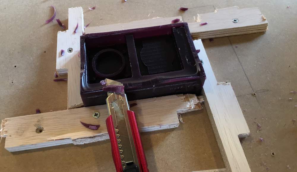
Removing your cast from your mold
After casting you are left with a cast in a mold, removing this can be difficult and is a delicate process.
- If you are like me and have some spoiled material, take a knife and remove the spoiled material
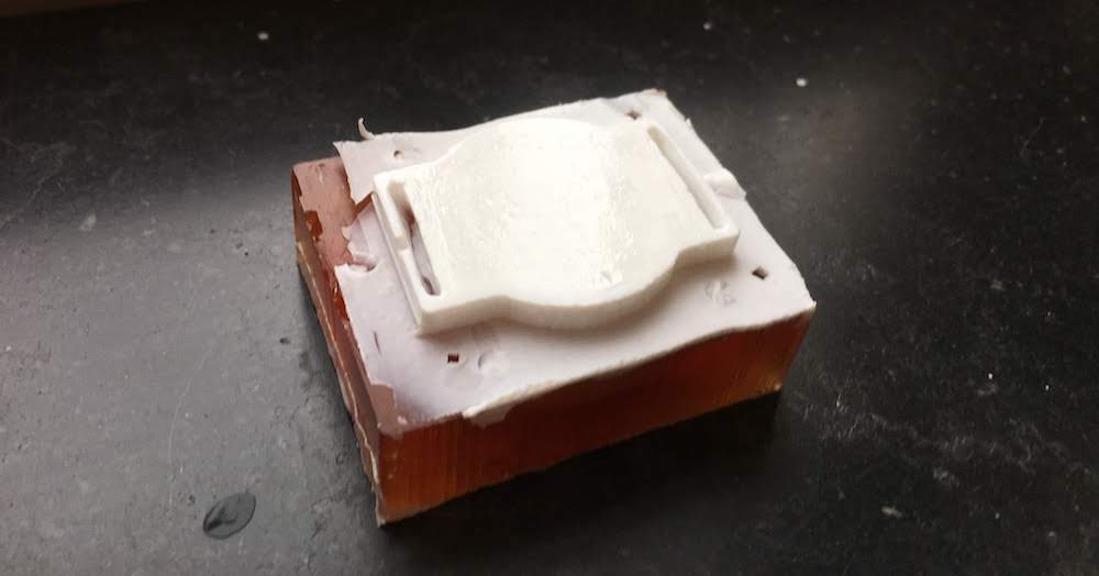
- Next slowly try to remove one half of the mold from the cast. If you have a flexible mold you can use a flat end of a spoon or spatle to slowly release the mold from your cast.
Start in a corner and slowly work your way towards the middle.
If you have a complex shape start from all corners and work towards the middle. - Next use the knife to remove the extra material around the molding lines.
I also had some material in my smartwatch band slots, that I removed with a knife. - Wash your cast and mold to remove the universal mold release.
- Clean your table, remove your waste and store your mold to be used for a next time.
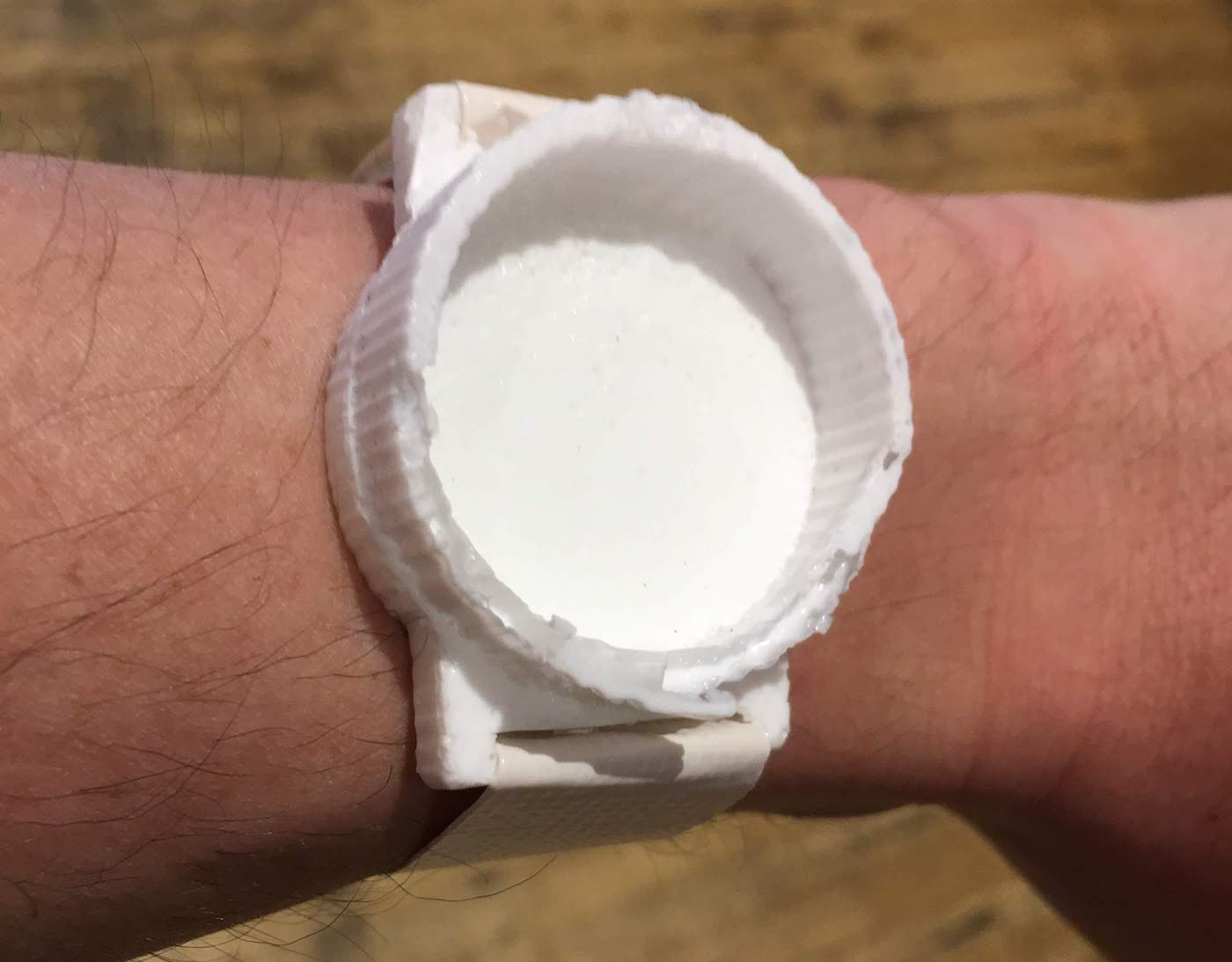
And for the final part, behold your cast and enjoy your result.
Fails
Forgot to set offset
I did not set an offset for the milling. Honestly I do not know how to set this, since this is probably different per size mill, so I probably first need to learn how to calibrate, determine the offset with different mills before I try again.
Fusion360 losing dimensions on shutdown
When I tried to simulate my first STL on the PartWorks 3D software, I noticed not everything was milled.
I did not left 3mm or more space between some parts.
To resolve this I went back to my design to make the spaces between the parts bigger.
Unfortunately Fusion360 forgot the dimensions that were fixed to these specific pieces,
and I had to edit everything by hand. It took me almost 2 hours to fix this issues, instead of a few minutes!
Next time I will try a different software tool to design in 3D, or not use Fusion360.
Working with malformed piece of wax
Unfortunately I had a piece of wax that whas malformed at the top.
This meant I head to not use almost 1 cm of top layer.
I decided to calculate this into my sketch design since we had to calculate the Z axis at the top of the wax.
This turned out to be more difficult, than manually cutting away the malformed pieces with a knife.
When I had to switch mills, from 5 mm to 3mm, I noticed the 3 mm mill was almost 1 cm shorter than the 5mm mill.
This would result in the milling mount touching the sides of the wax,
to resolve this issue I removed the sides of the was with a knife during the switch.
To soon!
I removed it before recalibrating the Z-axis for the new bit. It whas the first time I switched milling bits inbetween, so the recalibration of the Z-axis was something new for me for this machine.
I decided to try anyway, I lowered the Z-axis by 4,9 mm and tried the refined cut.
It turned out to be almost correct. When I looked at my refined mill, I saw I had to go about 2 mm deeper.
So I recalibrated my Z-axis 1,9 mm deeper and reran my refined mill.
Next time I would first make my piece of wax in a perfect shape before I start the final mill.
And I would not calibrate at the top of the wax, but at the base layer, this is always the same and much easier when changing mills.
Wax mold missing details
Because I did not set my Z-axis for the 3mm bit correctly, my wax mold was missing the connection holes and the slots for my armband.
I used a knife an millingbit to create the missing pieces by hand.
Although it was correcting a mistake by hand it was a good experience to edit a wax mold by hand.
And I can imagine me create more details by hand to a mold that cannot be created using the router because of the size of the milling bit.
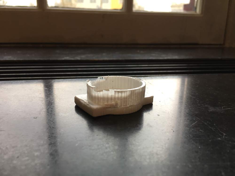
Ugly finish in wax mold
With our testmold our end result looked really rough.
We found that this was because of 2 reasons. We set the stepover size to big 50%, and we did not pass over the cutouts over the Y-axis direction, only the X-axis direction.
To get a nice finish use a small stepover size and mill over both Y-axis and X-axis direction.
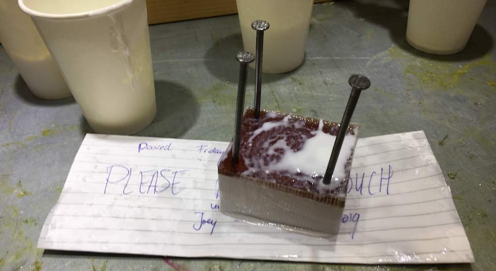
Not-fixin connectors
After milling I noticed my cast connectors where not the shape as designed. This was mostly because I used the wrong toolpath for drilling the casting holes and did not use the x and y milling directions for the nubs. I tried to create the holes using a milling bit by hand. This worked, but I chose a milling bit to large. This resulted in the holes of my cast being very tiny and the nubs of my cast being very big. I tried to create new holes using a millingbit on my cast. This did not work, the material was to flexible. Eventually I removed the nubs and used nails to connect the two halfs of my mold.
No pooring hole
I did not add a pooring hole in my wax mold.
At the time of designing the mold I did not know hwere to put it, and how to best create it.
I though I could always add that later after I casted my flexible mold from my wax mold.
Big mistake.
The PCM was to flexible to drill a hole in, also it was very difficult to create a hole using a knife.
Next time I will either directly create the pooring hole directly in my mold design,
or use a stick or straw to create the hole with my mold.
Too much mold release all over the mold
I put too much mold release over mold making the cast seep through the mold.
I tried to resolve this by cleaning the mold with a damp cloth, this did not work . Then I tried to apply tape to the sides. This also did not work.
In the end I just waited for the cast to harden, then apply some pressure on the mold and add the last bit of casting material.
Next time I will cover the parts of my mold that should not be covered with casting resolvent.
Air in cast
I casted my final cast with Smooth-cast.
This material is as liquid as water, making it perfect to cast using a mold with small details.
Unfortunately, I also had the problems of it seeping away from my mold.
I tried to resolve this by pooring the last part when the material was hardening.
And while pooring the material I also massaged the mold to massage away the air from my mold.
After removing my cast I noticed I still had some air at one side of my watch mold.
Next time I will make sure my mold is easier to keep closed preventing material to seep through the molding lines.
Also maybe I will try to use clamps to keep the two parts connected to each other.
Reflection
The casting week was together with the make something big week one of the most complex weeks I encountered thus far, though I think it is also one of the assignment I enjoyed the most after the make something big week and the electronics design week.
Eventually I finished this assignment 4 weeks later than the initial planning.
Partially because of illness, but also allowed it me to work more in paralel to the other weeks.
Casting material that takes 16 hours to dry means you need at least 1 full day to complete one step (even though the casting of the material takes you 2 hours at most). With a 4 step casting process, where you use 3 different casting materials, you need at least 3 days to complete your work:
- On Friday design wax mold and make wax mold
- On Monday cast flexible mold
- On Tuesday cast final cast from flexible mold mold
- On Wednesday remove final cast and present to group This combined with the group assingment on Thirsday, means you have a full week where nothing can go wrong, because it if goes wrong you cannot complete your week before Wednesday, and the relfection at Wednesday is you presenting for example that you are stuck at step 2, because you have to redo your wax mold. As with the make something big assingment, I would advice this week to be something you are allowed to finish in 2 weeks. Making two assingment overlap.
As described in my fails next time when I would design and create a mold, I would use connectors using ridges and incorporate a pooring hole in my design.
Also I would use more time for milling allowing me to mill both over the Y and X-axis and having a nicer finish.
And if I apply universal mold release, I would make sure it is only applied on the mold part were the cast will be, not on the parts were the molds connect!