Week 8. Computer Controlled Machining
8. Computer Controlled Machining
Assignment
Group assignment: “Test runout, alignment, speeds, feeds, and toolpaths for your machine”
Individual: “Make something BIG on a CNC machine.”
Software
PartWorks (special version of Vectrix software for Shopbot to generate G-code)
Shopbot controller software
Illustrator for designing cutout
Hardware
Shopbot
Shisel
Handdrill
Screws
Files
Illustrator file of pirate chest design(3.1 MB)
G-code cutout 5mm
G-code cutout dogbones 5mm
G-code chest decoration 5mm
G-code screw holes 5mm
PartWorks file piratechest
Before your start
Safety first!
- NO long hair, long sleeves or lose ropes ect! You do not want to get stuck in the machine.
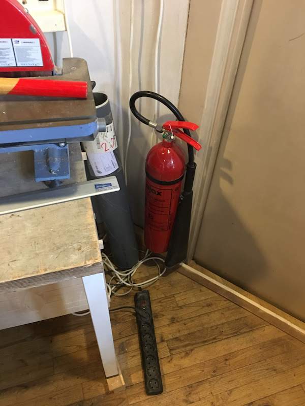
- Know what to do in case of FIRE! Know where the fire extinguisers are.
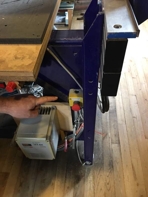
In case of even one spark: turn OFF the spindle and machine and check if you did not cause a fire in the vacuum cleaner. - Know where the emergency stop is.
- Never touch the machine when powered, always first turn the power off.
- When you stop the cutting process always lift the spindle and turn of the spindle to prevent fire!
- When the machine is on you never leave the device, but stay to monitor your progress.
- Check if your material can be cut using the shopbot. If you do not know the precise contents of your material you are not allowed to cut it.
- If you do not know what you are doing, ask somebody to help.
- Check this website for great milling tips!
Getting to know the Shopbot (group assignment)
Group assignment: “Test runout, alignment, speeds, feeds, and toolpaths for your machine”
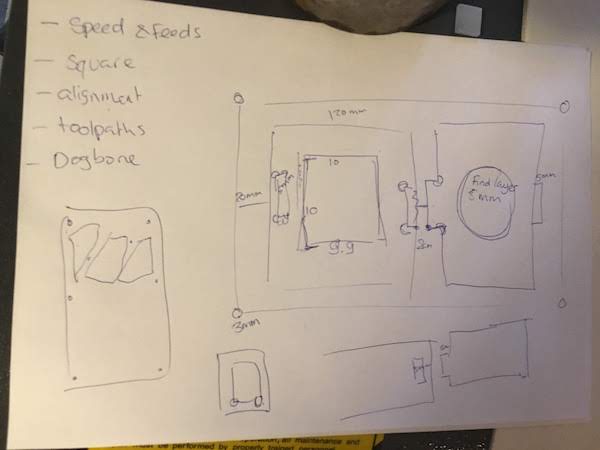
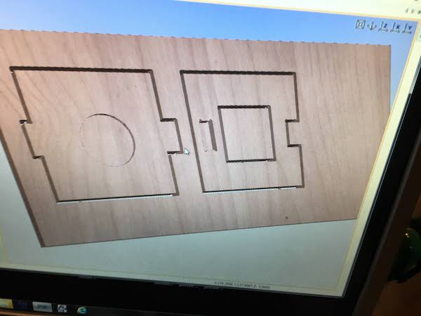
For our group assignment we made a test design that included:
- cutout toolpath
- pocket toolpath
- dog-bone toolpath
- t-bone toolpath
- square
- circle
- joints
For the cutout we made cutouts for the pieces, but also cut a square from the piece itself, to be able to see the offset needed.
We made a circle and square to see how straight and accurate the shapes would be.
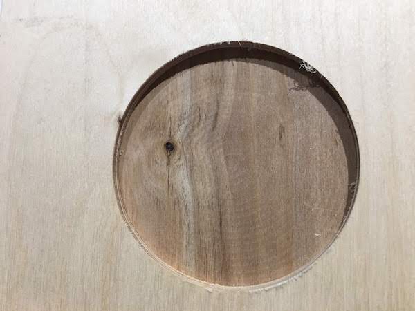
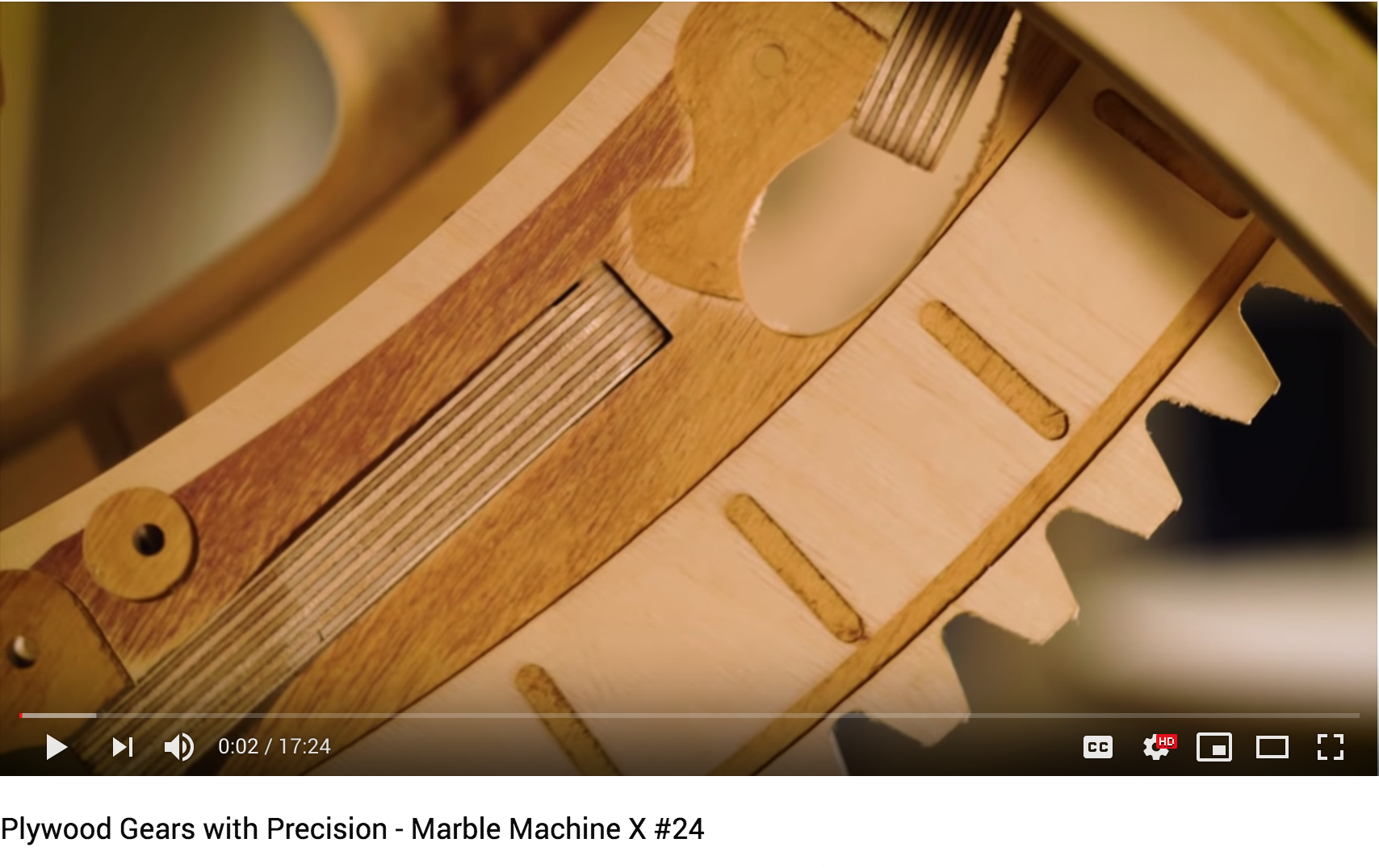
We made a pocket and tried to hit a dark glue-layer to get a nice contrast. I was inspired by this idea by the artist Wintergatan, he is making a Marble machine using the CnC router. See an impression of his work at the results section of our group assignment.
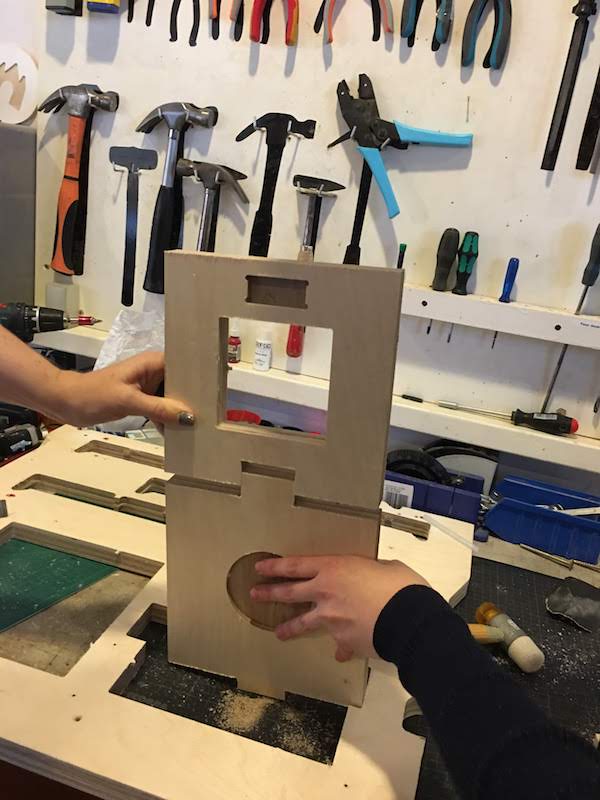
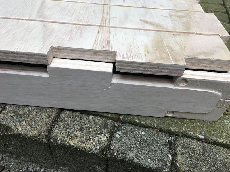
We made two type of joints( pocket join and finger join) to see the difference and try out the dog-bone and t-bone toolpaths.
Our progress was as follows:
-
We made a design on paper with our criteria
-
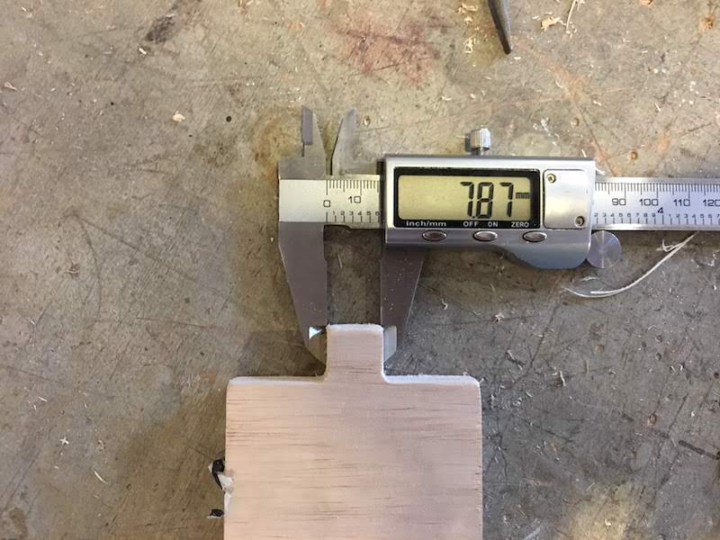
We chose a piece of wood and measured the dimension of our wood: height 330 mm
width 700 mm
thickness 23.8 mm
-
We transfered the design to Illustrator using our new dimensions.
- We left 3 centimeters between the squares to allow for easy cutout and to put a screw inbetween the cutouts to fix the plate to the sacrificial layer.
We decided on the 3 cm by taking our mill dimension 5 mm times 2 adding dimension of the screw and adding a margin: 5 * 2 (cutouts) + 5 mm screw + 5 mm margin * 2 + 5 mm margin (to account for errors) = 3 cm -
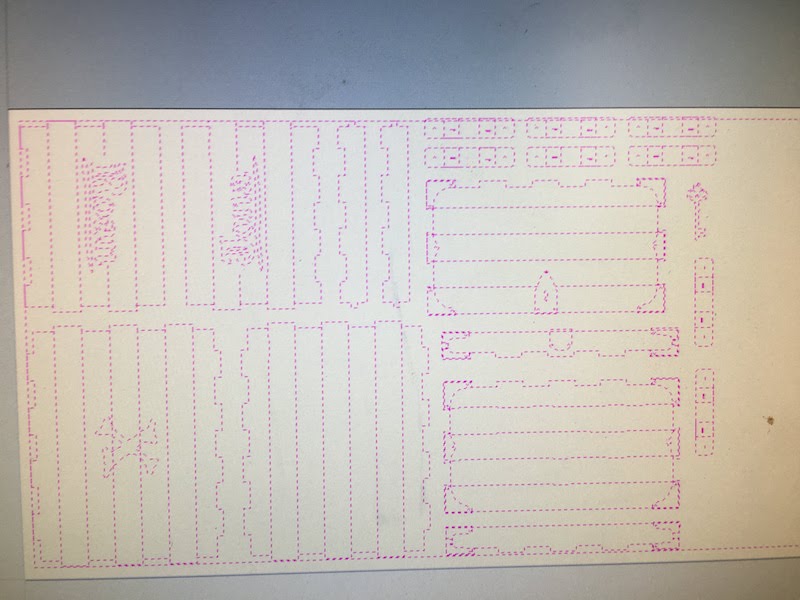
We saved our design as an Illustrator file and imported it in PartWorks.
Before importing the design we created a new file in ParkWorks with the dimensions of our wood.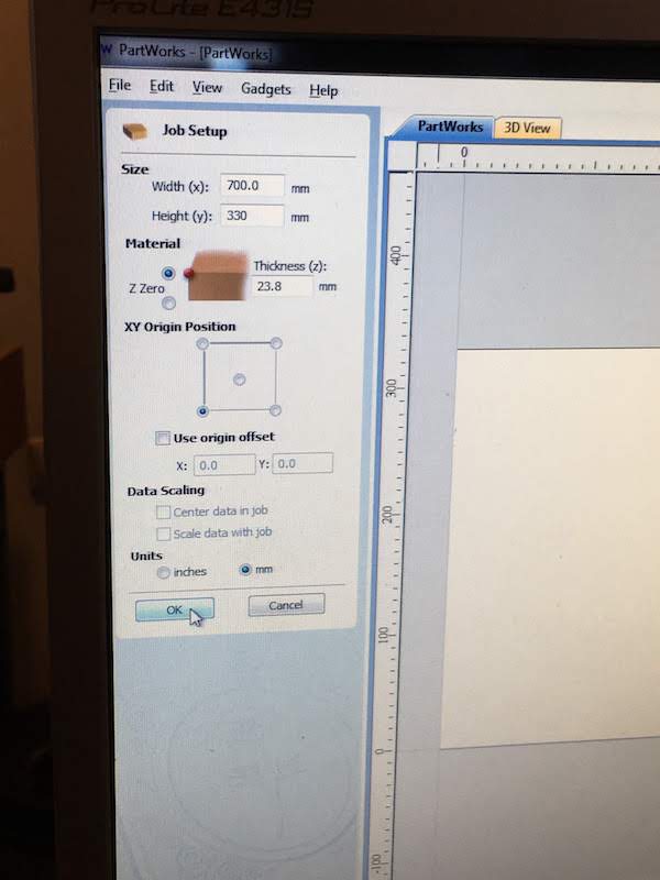
-
For each different type of milling we made a separate toolpath, one for the inside cutout, one for the outside cutout, one for the pockets, ect.
During the creating of our toolpaths we checked the simulation to see if everything turns out the way it should be.
-
For the cutout we milled about 0.1 mm further than the material, placed small tabs and assigned the dog-bones to the finger join cutout and the t-bone to the pocket join.
- Last we created a toolpath for the screw holes. We directly exported this screw holes toolpath, gave it a clear name including the mill size and then deleted the toolpath from partworks to make sure we would not include it later in the process.
- We ordered the remaining toolpaths to make our pockets first, then the inside toolpaths and last the outside toolpath.
- We exported the reamining toolpaths and gave it a clear name includignt he mill size.
-
Next we prepared the Shopbot (cleaning, mill, turning on vacuum machine) and started the milling software.
-
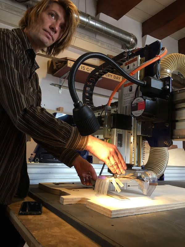
We placed our material on the sacrificial layer, but did not attached it. In stead we calibrated the Shopbot to the wood and milled the screw holes.
-
Next we turned off the spindle placed the screws and recalibrated the Z-axis of the Shopbot.
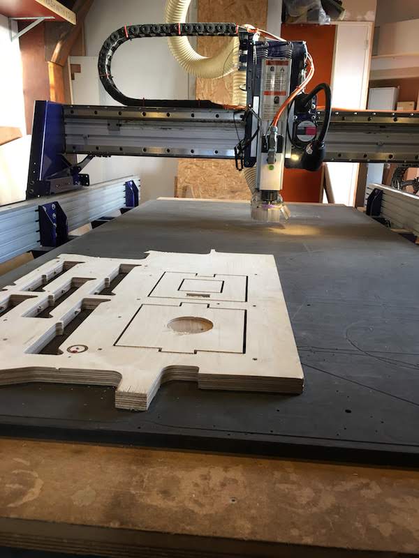
- We loaded our design toolpath and waited untill the Shopbot was finished.
-
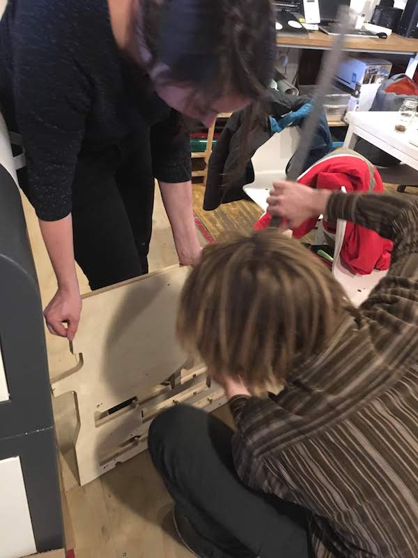
We cleaned the wood, removed it from the bed and saw we only toughed the sacrifical layer. Nice! Next we removed the small tabs with a shisel.
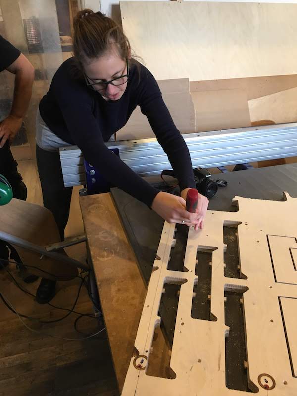
-
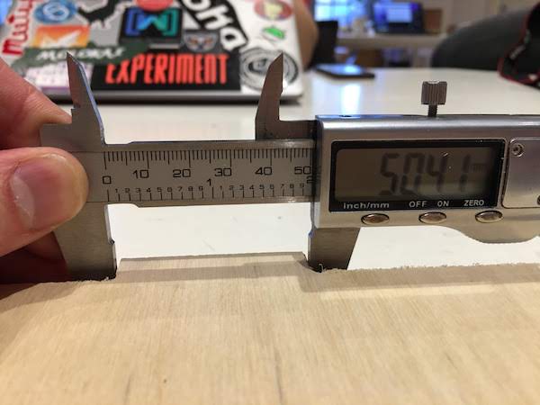
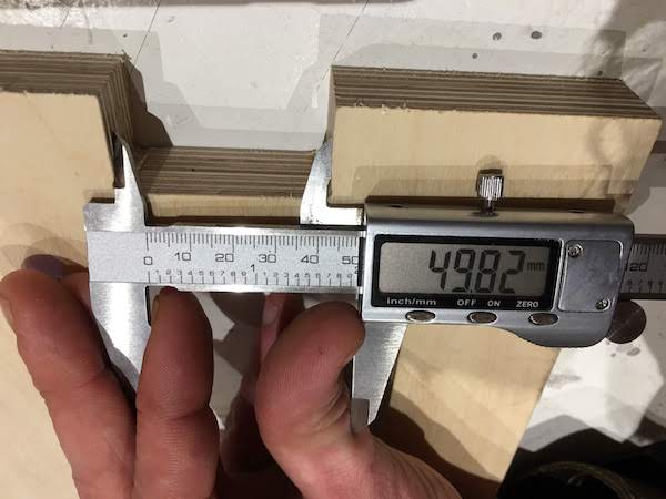
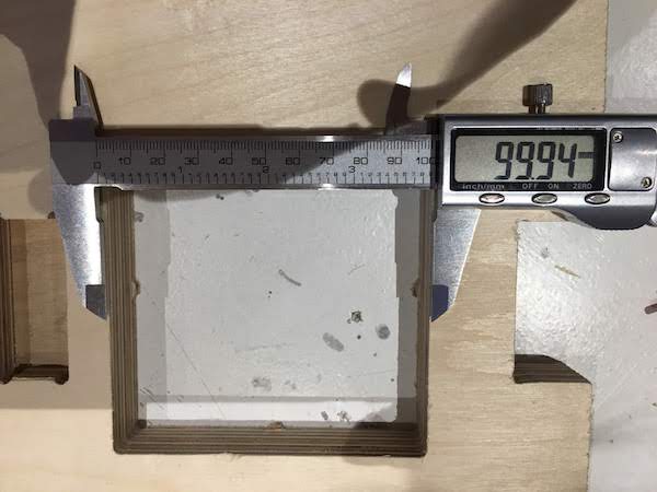
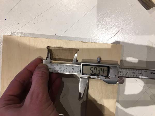
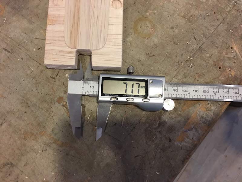
We forgot to measure the offset before removing the material, but tried to determine it by measureing the difference in the finger joins.
It was very difficult to measure, but the difference is about 50.4 - 49.8 = 0.6 mm . This difference made it almost impossible to join the two pieces of wood with the pocket join.
- Overal the mill is very accurate and the circle pocket turned out to be really nice with the difference in contrast. Thanks Wintergatan!
Making something big with the Shopbot
Creating a 2D design for the Shopbot
We are going to create something big with the Shopbot.
We will walk you through the whole process, from inspiration, to design, to milling, to construction.
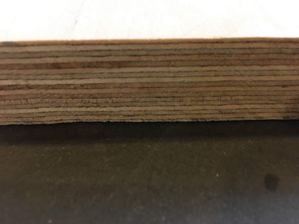
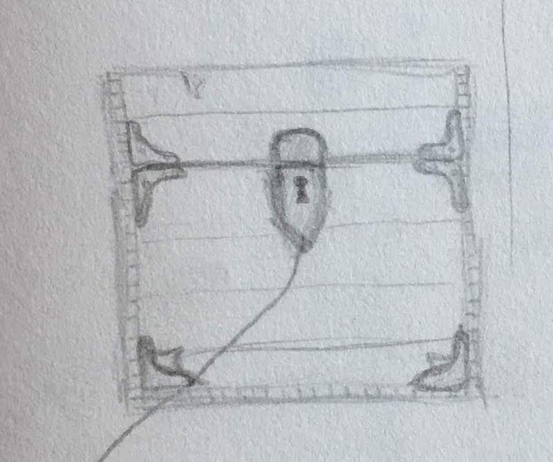
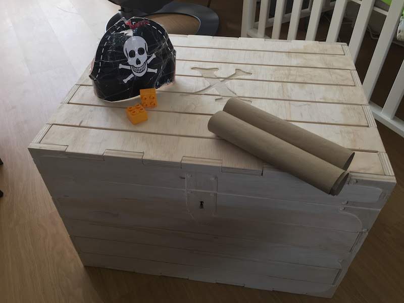
In this example we will be creating a pirate chest out of a single sheet of plywood.
We have as criteria:
- it should be made from a single piece of plywood (dimensions 2500 x 1220 x 15.3)
- use almost no glue or screws
- the chest should look as a pirate chest
- use only one type of mill 5 mm two flutes
- be made within 3 hours of milling time
Inspiration
For inspiration for our pirate chest, I created a Pinterest moodboard, containing all kind of great wooden chests. Some are made with a CNC router, others by hand.
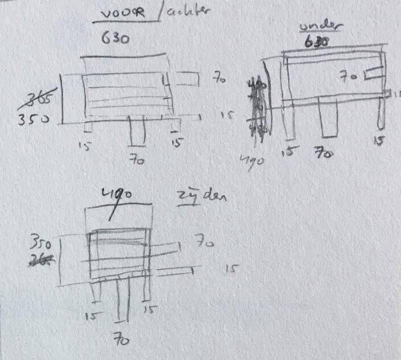
From this moodboard I created some sketches of possible pirate chests for us to create containing concepts as joins, lid and planks.
Important questions to decide on are the type of lid, joints and size:
For the lid we can think of a solid, tampered, curved or more organic shaped. To keep things simple, I chose to first make a basic solid lid.
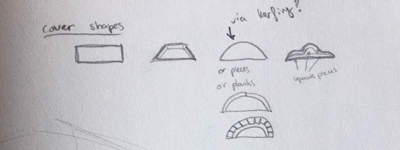
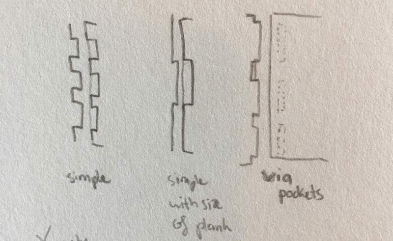
For the joints we considered, simple small joints, joints the size of a plank, and joints via pockets. I schetched some different designs for the joints, and decided to make big joints and the size of a plank 70 mm. This also allows me to decorate the joints with pockets.
For the chest size we looked for inspiration at boxes that are convenient to store stuff in, look storage boxes.
A large storage box of the Praxis hardware store is 580 by 400 by 300 mm.
This is the size we will follow for the base of the chest. On top of this base we will provide the lid.
Box size: 580 x 400 x 300.
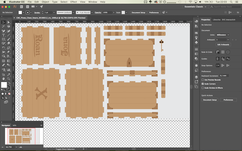
Designing in Illustrator
Having decided on the basic shape I could start designin the box in Adobe Illustrator. I considered to use Fusion360, but several team members indicated the export of Fusion can give issues with the PartWorks software. To prevent issues with exporting I went with Illustrator. The advantage for me is that I better know Illustrator than Fusion, so my design time will probably be shorter, but with Illustrator I cannot use parametric design as in Fusion, meaning that changes in dimension mean more edit time than in Fusion.
I created a new file in Illustrator with the dimensions of my wood: 2500 x 1220 mm
Within this canvas I created a “save to design are”. This area has a margin of 30 mm from all edges. This will later allows me to put screws in the sides of my wood and not have to worry if the machine will mill at the screws.
My save area dimensions are: 2440 x 1160 mm
Next I created the front panel of: 580 x 300 mm.
I used the rectagle tool. To quickly create a rectangle the desired size, you can click with your mouse on the screen and enter the dimensions.
Within the rectangle I drew the cutouts for the joints, size: 70 x 15.3 mm
I quickly realized a size of 580 by 300 mm will not work with 70 mm finger joints. After all 580 / 70 = 8.25… not a round number!
I adjusted my box dimensions to fit within a factor of 70.
New dimension: 630 x 490 x 350 mm
During the design I often got lost in dimensions and had to work on different levels of requirements, therefor I made the following list of priorities for my design: pratical aspects first, then estetics.
level 1 material, the material is use has a dimension and thickness
level 2 box size, the box I want to make has to be practical in usage and fit on the material
level 3 plank size, I decided, I wanted to use a plank size of 70 mm, the box sizes need to fit with this size.
level 4 esthetics, the box has to look as a pirate chest given the dimensions and limitations of the assignment.
Further I created an Excel sheet containing all the dimensions of my box and the material I wanted to use, this allowed me to keep an overview of all the panels and to see If it would fit the material.
During designing I noticed when you color and fill the lines for their different cutout/kerf/pockets settings, it is easier to get an overview of the final result, also this will help when setting the settings in the PartWorks software.
To get the design from from Illustrator to PartWorks use the following steps:
- Ungroup all groups
- Make sure you have closed your lines and no duplicate lines
- Create oulines of your text. Your text will now be lines and you do not need to transfer the font with your desing.
- Last store your design as an .ai file.
From design to G-code for the Shopbot
We use the PartWorks software to generate the G-code for the CNC milling machine (Shopbot).
The PartWorks software runs on a special computer connected to the Shopbot.
Start by turning on the computer that is connected to the Shopbot, login with the Fablab account (no password).
Transfer you file from your USB stick to the computer and place it in the fablab project folder with a folder with your name.
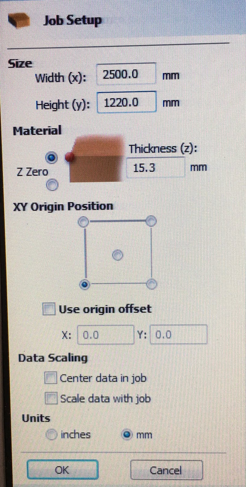
Start the Shopbot software PartWorks and Create a new Job.
Input your dimensions of your material, in my case:
width: 2500 mm
height: 1220 mm
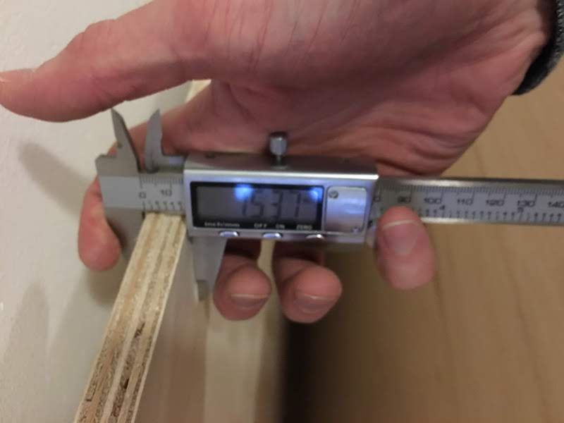
depth: 15.3 mm (I actually measured 15.37, and 15.28, and decided to average on 15.3)
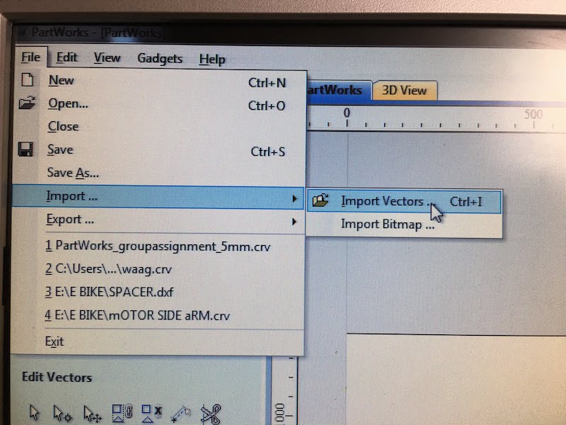
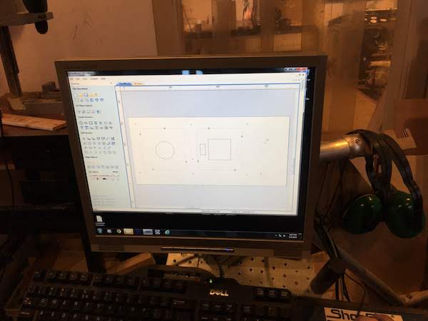
Import your design via:
File -> Import… -> Import Vectors… (our illustrator file)
Or use Ctrl + I
 Now select the lines you want to use to cut/mill.
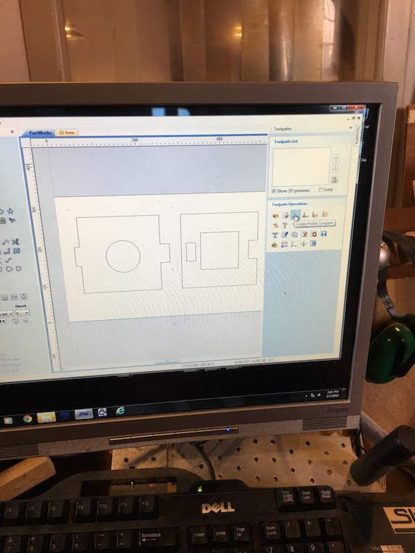
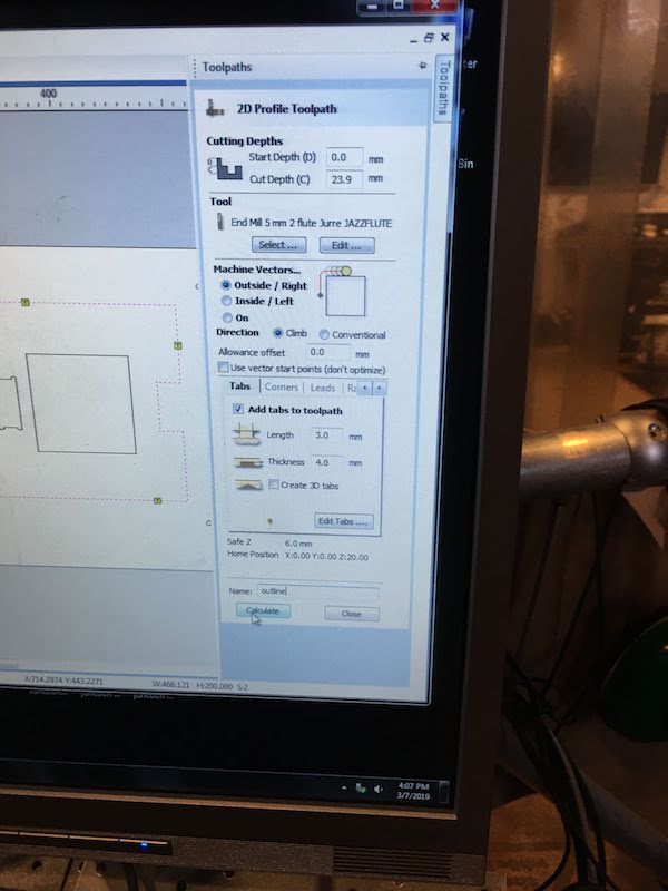
Go to Toolpaths and select the 3rd icon, “Create profile toolpath”
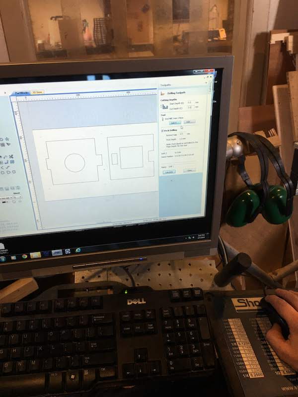
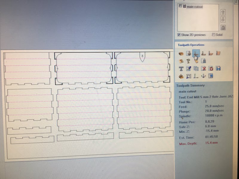
Now put in your cuth depth in our case we use the thickness of the material + 0.1 mm to make sure we are through our material, and because our material has a variancing thickness of 0.05 mm.
cut depth: 15.4 mm
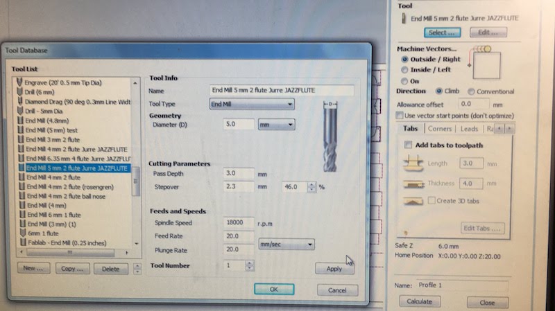
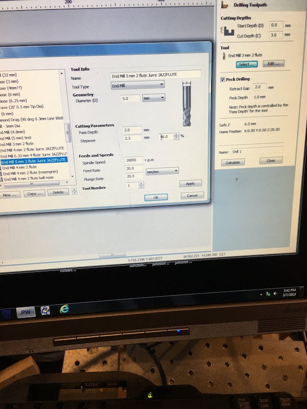
Next select your mill, We are milling with a End mill 5 mm two flute mill.
Put in the following parameters:
| Mill settings | |
|---|---|
| Diameter: | 5 mm |
| Pass depth: | 3.1 mm |
| Stepover: | 48% |
| Spindle feed: | 18000 |
| Feed rate: | 40 mm/s |
| Plunge rate: | 30 mm/s |
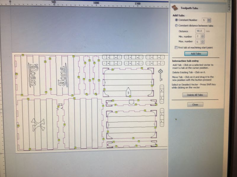
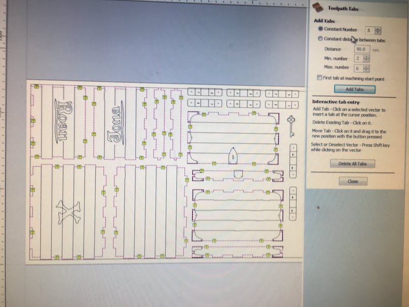
Next select tabs and select “Edit tabs” button.
Select the amount of tabs you want. Recommended is to place two tabs per 50 cm line. I place two tabs at each side of my cutout plates.
Next select the “Add Tabs” button. This will place the tabs on the screen.
Take a look at your tabs, and see if tabs are placed inconvenient. With you mouse you can remove and place tabs.
Select “Close” when you are finished with setting your tabs.
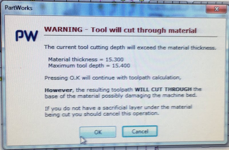
Give your toopath a name and select “Calculate”.
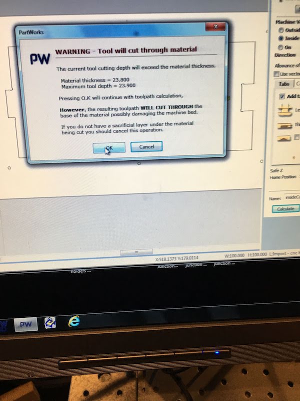
You will receive a warning that you will be cutting through your material. Check if the message gives the information you agree with and continue if everthing checks out.
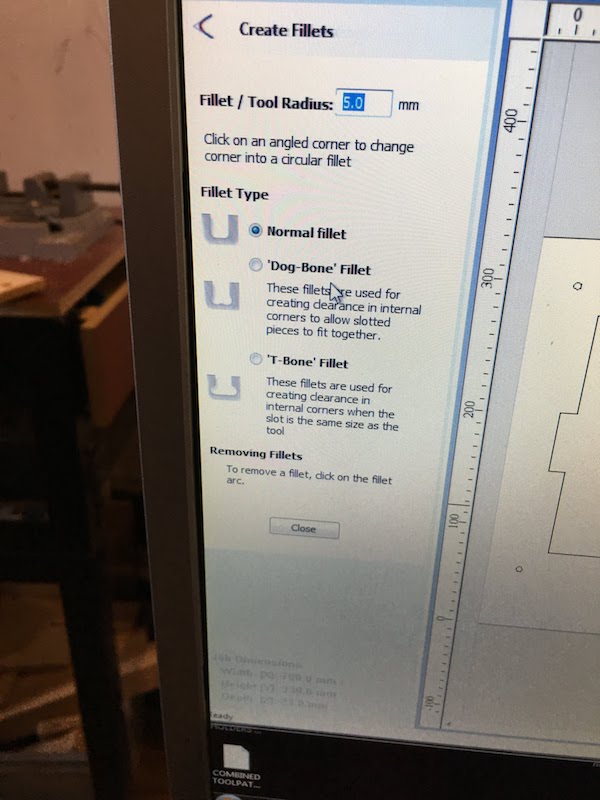
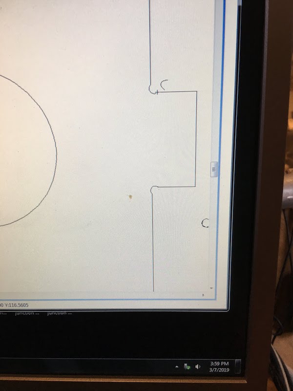
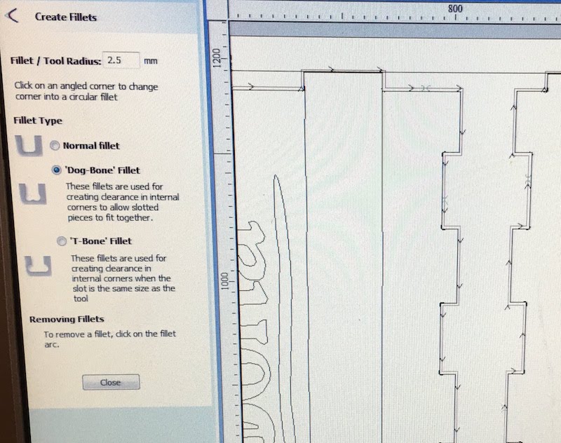 Last if you have joins you want to add fillets (dog-bones or T-bones). You can apply this by selecting the “Create Fillets” option in the left menu bar. Next select the type of fillet (dog-bones or T-bones), and click with your mouse where you want the fillets to be. This will mostly be the corners of your cut.
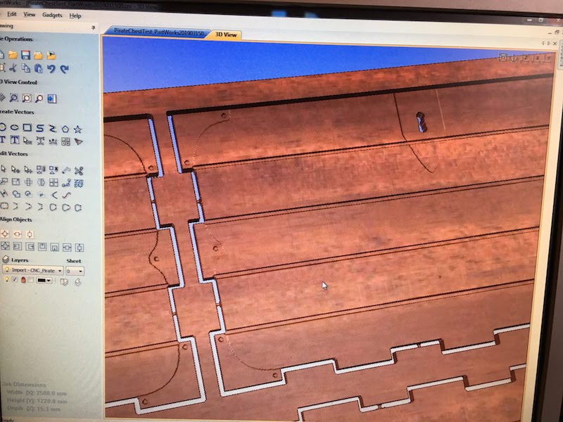
Next you will be able to simulate your cutout.
Select “Preview Toolpath” to see a simulation of your toolpath.
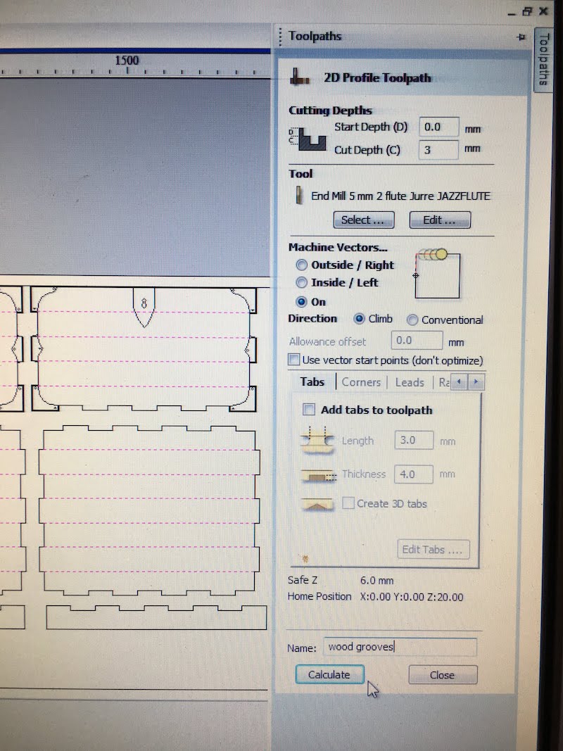
Next select your lines you want to kerf and create a toolpath for these lines. For our lines we select:
- cut depth 3 mm (to get to the third wood layer)
- machine vectors: on the line
- give it a name “wood grooves”, and calculate.
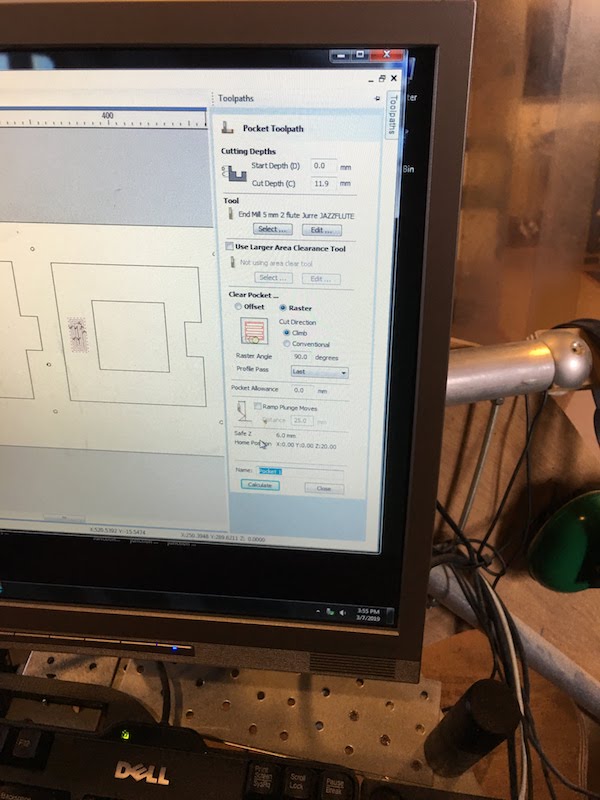
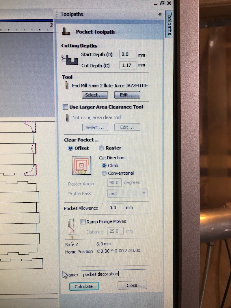
Next we select our pockets and create a toolpath for these lines
- cut depth: 1.17 mm (pocket for my second wood layer)
- machine vectors: inside/left
- name: “pockets”, and calculate
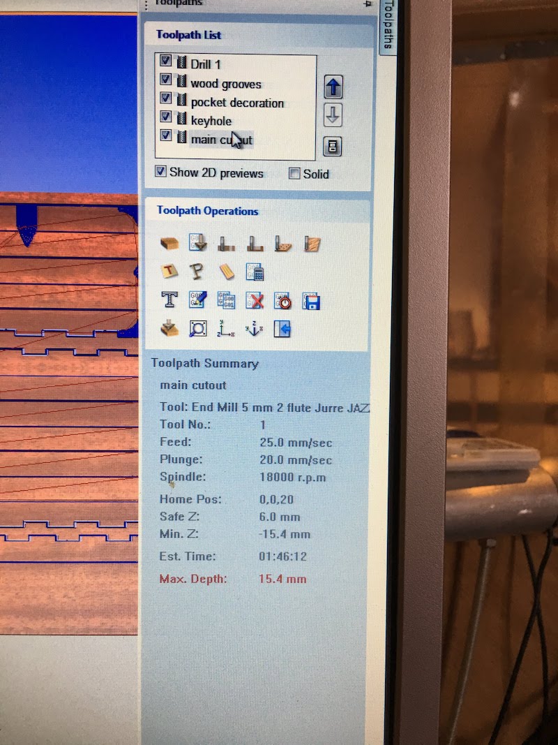 Having created all the different toolpaths we order them in the correct sequence.
Leave the cutout for last.
After orderning select the pocket and kerf toolpaths and export them to G-code using the “Save toolpath” icon.
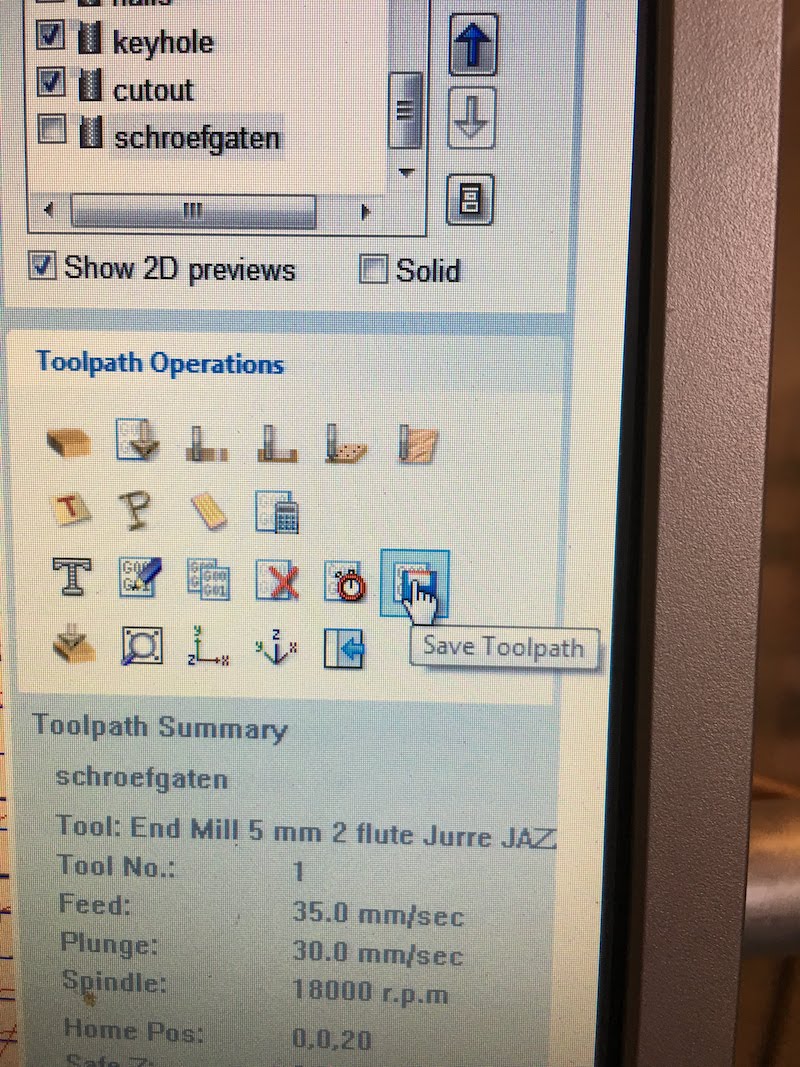
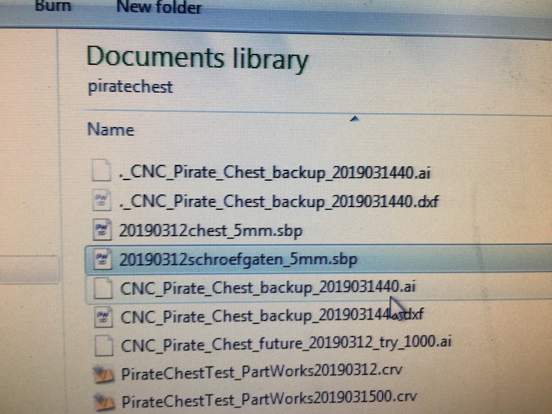
Chose a fitting name and include the mill diameter in the name. This way you are sure you have to correct G-code when selecting it in your milling software.
Next select the cutout toolpath and again save is at G-code under a fitting name. Include cutout and mill diameter.
From G-code to milling with the Shopbot
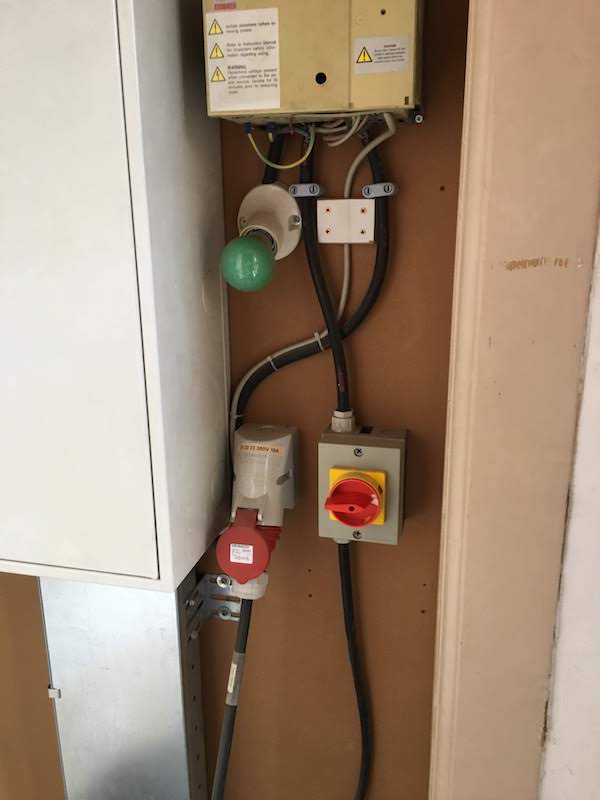
Having created our G-code we can now continue to the next step, mill our design with the Shopbot. Before doing anything with the Shopbot you first need to know your safeties. Look at the “Before you start” section.
Know knowing what to do in case of fire, and how to keep everything save we can start touching the Shopbot.
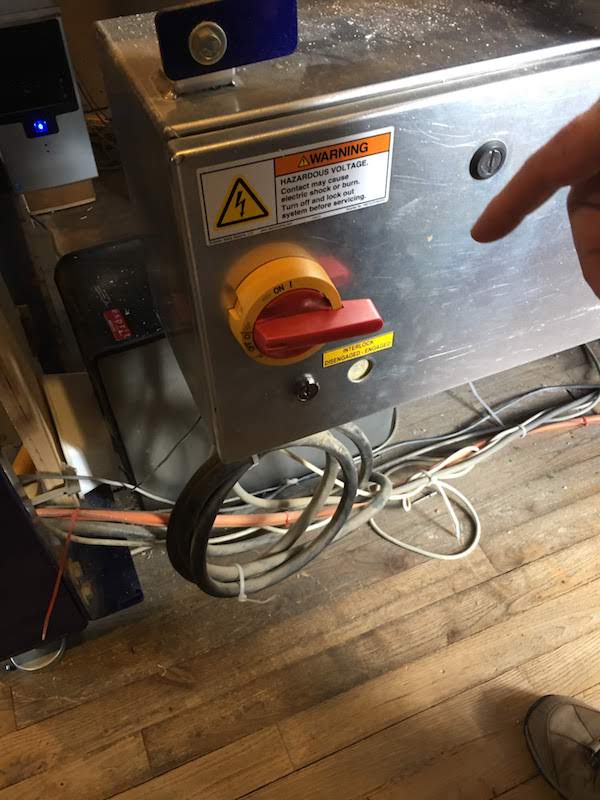
Make sure the device is turned OFF.
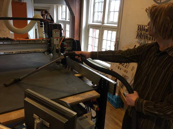
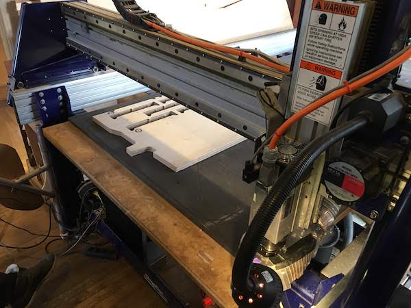
Next clean the sacrificial layer. In our case it is this nice black layer that we can use to fix our material on and that is nice and flat.
Clean the sacrificial layer by vacuuming all the dust and residu material, and by sanding away imperfections from screws.
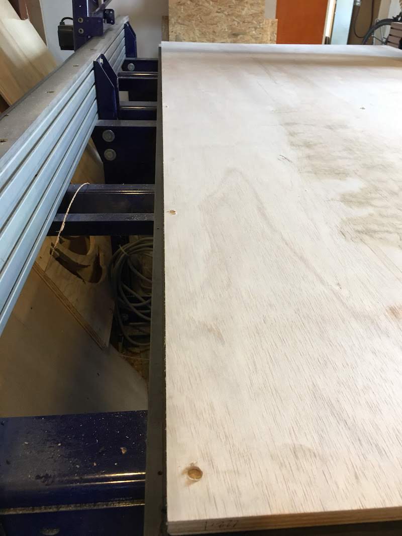
After cleaning place your material. Our sacrificial layer has a nice small guiding edge at the left side to lay your material straight.
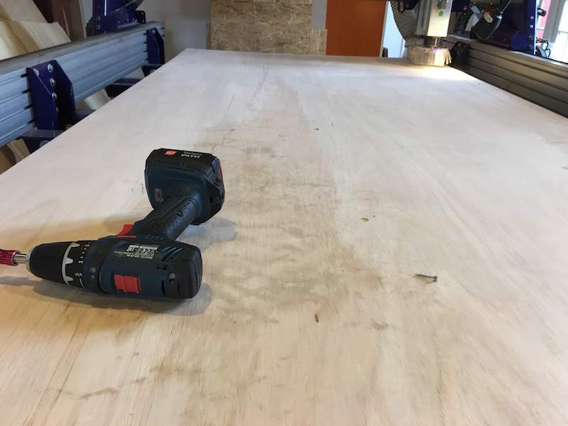
Make sure your material is flat than fix it to the sacrificial layer with wood screws. Make sure the screws go into the sacrificial layer, but not through!
Also make sure to put enough presure on the wood to not raise the wood.
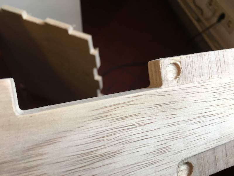
Place your screws at the edges of your material, and make sure you do not have planned any milling near the screws.
Protip:
You can also create a special toolpath for your screw holes fore placing your screws. I did this in the end to make sure I would not mill on the screws.
Do be carefull to not include your screw holes toolpath in the other milling toolpaths. My advice would be to create the screw toolpath, generate this G-code, save it under a name as: “DANGER_screw_holes_toolpath_5mm”, and then through away the toolpath from PartWorks. This way you cannot easily make mistakes later in the process.
When you use a toolpath for screws you need to follow the steps:
- first need to place your material
- go through the whole procedure of setting up the Shopbot
- mill the screw holes
- turn off the spindle and move the spindle out of the way
- fix your material to the sacrifical layer
- then recalibrate your Z-axis before your start with your actual milling
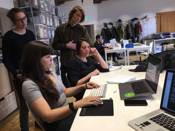
When I wanted to start milling, there were many people around (including from the Dutch radio!), to avoid making mistakes I wrote down a quick procedure to follow:
- Vacuum ON
 .
. - Mill on
 .
. - Shopbot software launch
. - Calibrate x, y, z axis (z axis in the centre of the plate) (see calibration section for details)
- Load screw cutout in Shopbot sofrtware
- Spindle on 180000 and vacuum ON
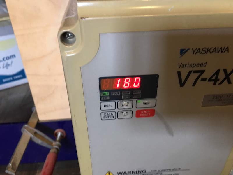
. - Mill Screwholes
- Spindle and vacuum OFF
- Move mill out of the way with software
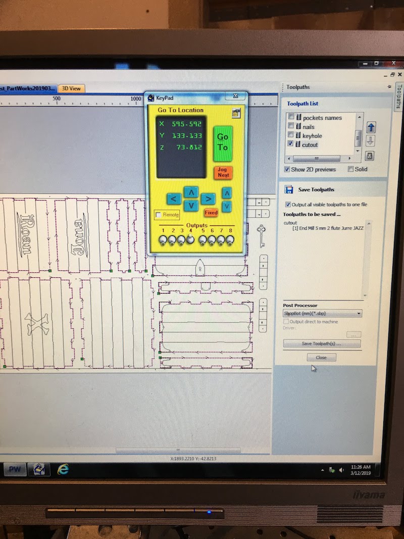
Protip: If you want to quickly move the Shopbot (while the spinle is off) press K to get the keypad, instead of selecting this option from the menu.
 .
. - Measure screwholes and set screws
. - Recalibrate Z-axis
- Load milling file for pockets and cutout
- Spindle and vacuum ON
- Start milling
 .
. - After milling: Spindle and vacuum OFF
. - Check if everything looks ok (inserted this option after fails)
- Move mill out of the way and turn OFF
- Vacuum material
- Remove material
- Vacuum table .
- Remove cutouts from material
- Cleanup waste, vacuum and use a saw to make your left overs smaller.

I pretty much followed these steps as determined. Before discussing my result I will describe placing a mill and calibrating
(Re)Placing mill
For (re)placing a mill. First make sure the Shopbot is OFF and the spindle is OFF, and the key is not machine.
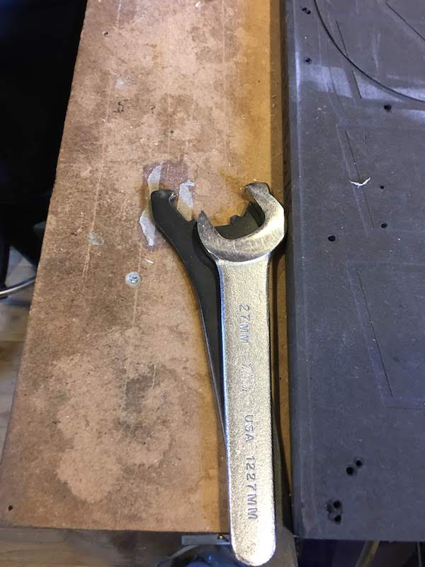
Next get the tools for replacing the mill.
Move the vacuum scirt up (there is a small screw at the back of the spindle) and remove the old mill with yor tools.
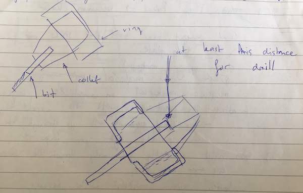
Find the mill you want to use and select the fitting collet, it should fit tight when only holding with your fingers.
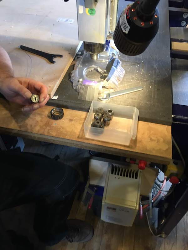
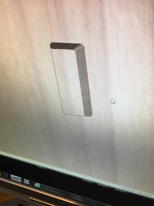
Place the mill in the collect and the collet in the ring. Make sure the mill is placed as in the image.
Tighten the mill to the spindle monkey tight, but make sure it is not to lose, we do not want to have a flying mill.
Last check if your mill is in straight and move the scirt down.
Calibrating
- Place your material and attatch it to the sacrificial layer
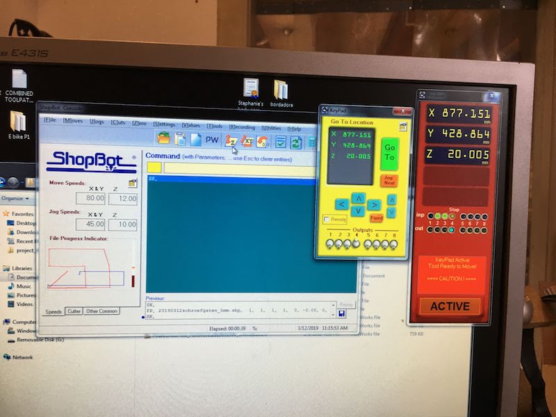
- Start the Shopbot and the Shopbot controll software
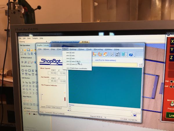
- Select the option XY icon with the arrows in the software. The Shopbot will now move to its default X and Y 0.
- Move the Shopbot to the new start position. You set a X,Y 0 in your PartWorks software, most of the times this is the left bottom corner.
Remember that the Y-axis is the short part of the Shopbot, so left bottom is actually right bottom on the picture where you see the mill. - Next selec the Zero X and Y option in the menu.
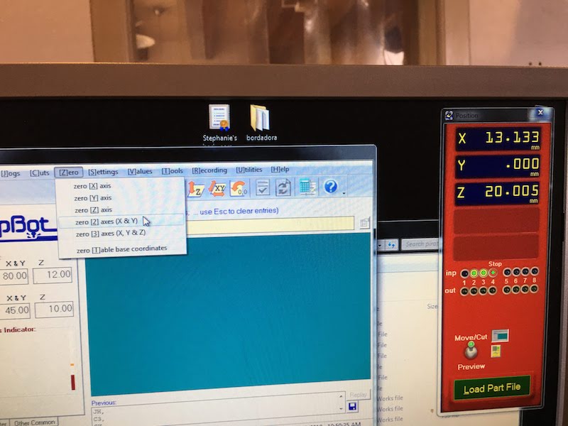
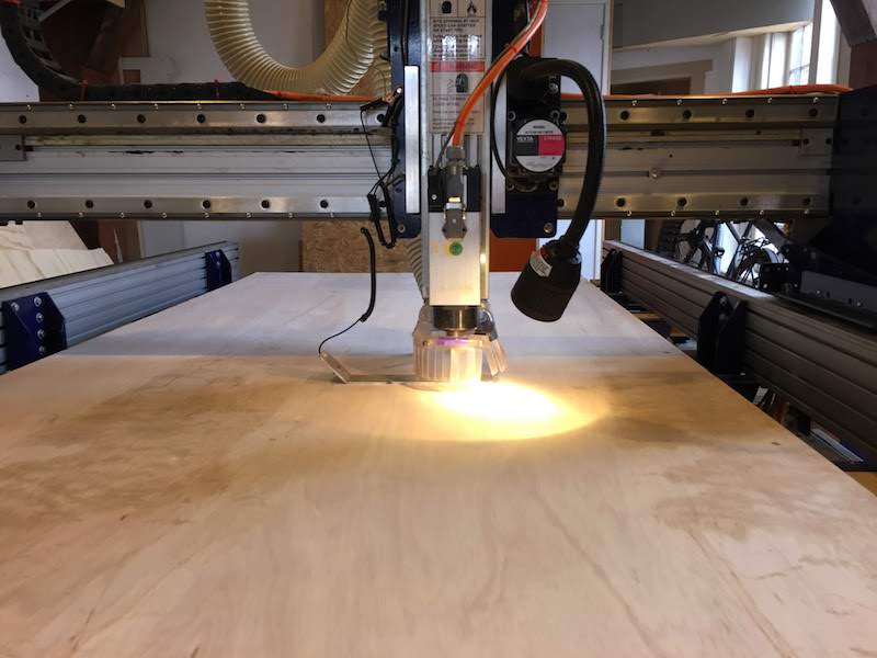
- Next move the mill to the centre of the material.
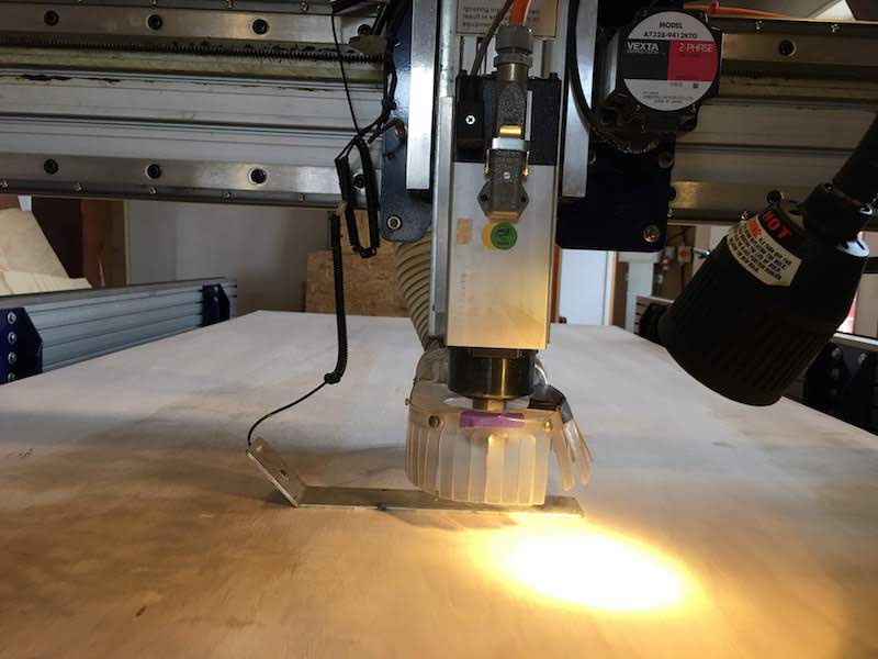
- Place the metal plate under the mill and select the Z icon with the arrows in the software.
You will receive a mesage to place the plate. If you placed the plate press ok. You will get a Z-contact did not clear error, ignore this.
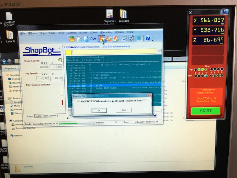
- Next move the mill up and remove the plate. You are now ready to start milling.
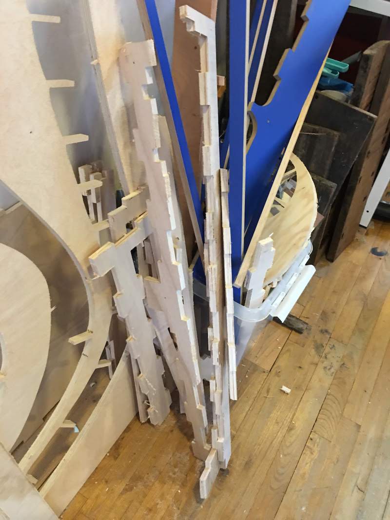
Result
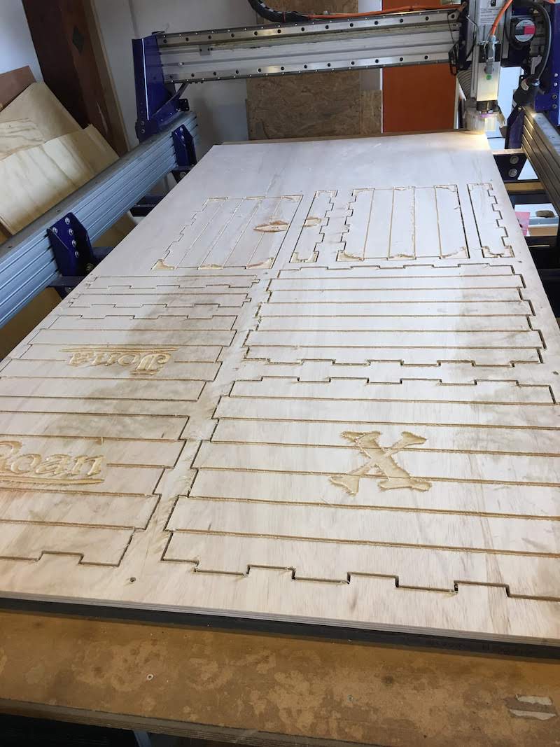 After milling I had a nice cutout, but found out I made some mistakes (see also my fails): I forgot dog-bones and to set an offset. I repaired these errors by sanding and a shisel, I had to remove remaining wood curls anyway. I only removed some material to keep a tight fit and used a hamer to attach the pieces.
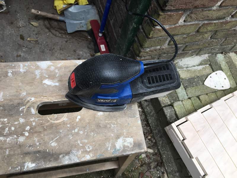
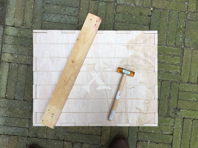
The final join were really tight and I did not had to use any glue!
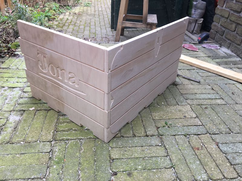
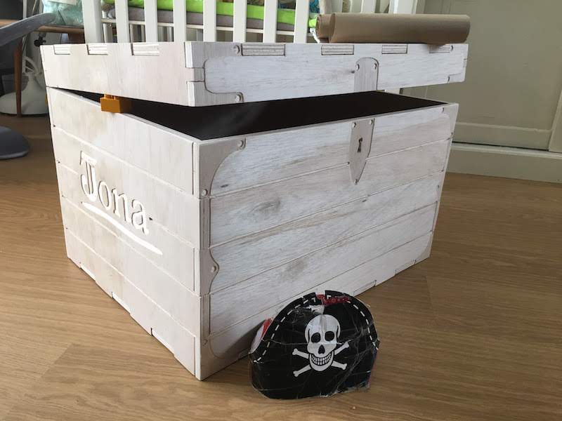
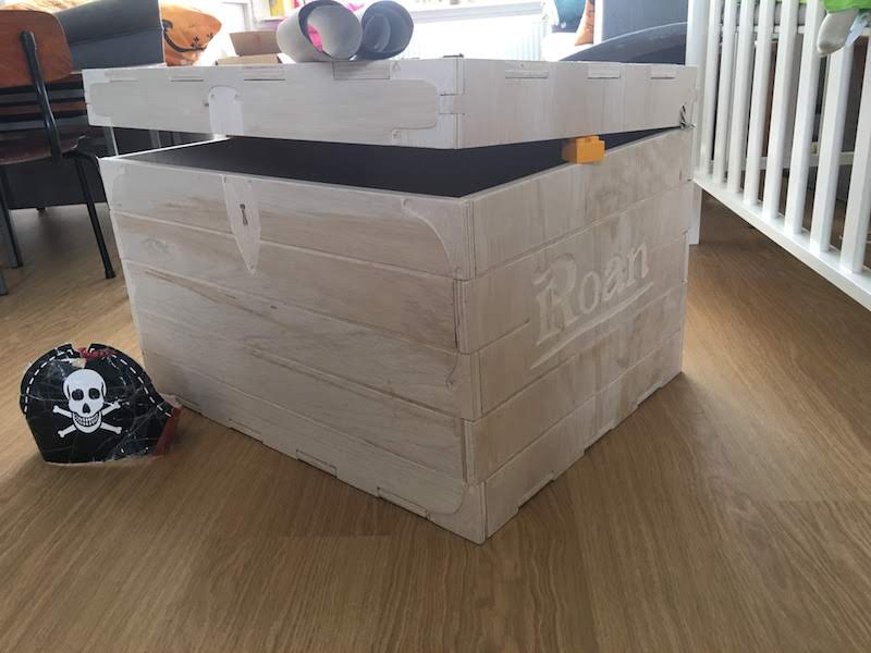
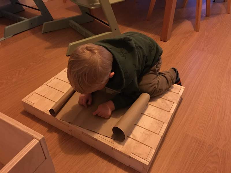
After hard work I was able to finally put all the pieces together, make some nice pictures and present the end result to my son, who is really happy with his new pirate chest!

Fails
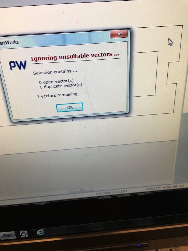
Illustrator duplicate vectors
In our group assignment we made our design in Illustrator and imported this in the PartWorks software.
There we noticed we had duplicate vectors, meaning we had multiple of the same lines.
In PartWorks you can resolve this by selecting all vectors, then selected “edit” and the option “select all duplicates” and then delete them.
Illustrator align option not pixel perfect
When creating my design in illustrator, I wanted to align my pockets in line with my cutouts. I thought I could sue the align option of Illustrator. But after zooming in I found out that this function is not pixel perfect. You are better of aligning the vectors by hand. If your vectors do not overlap you will get nasty results with milling.
Expensive mistake: Forgetting material thickness
When first creating the finger joints I used the dimension: 70 x 15, forgetting my material is 15.35 mm thick! I later had to adjust all my joints, which takes a lot of time in Illustrator, since Illustrator does not support parametric design.
Next design will definitly be with a tool that allows for parametric design.
Out-of-time
Designing the cutout in illustrator took much more time than I had planned. I had given myself 6 hours to design my cutout.
But I kept having problems with designen a proper pirate chest, due to dimensions and forgetting material thickness, ect.
When I noticed I was out of time, I made a new plan. I would first make a basic setup of my box, not a fancy one, made the dimensions in Excel, fancy it up a little bit.
Then try my desing in the PartWorks software, see how uch time the milling would take, and tweak my design to allow for a shorter milling time.
I ended up using a higher feedrate of 40 mm/s and a plunge rate of 30 mm/s and pass depth of 3.1 mm to allow for less passes and make the passes faster.
I could use these high settings, because I hade soft wood and we had a sharp mill. During milling I kept listening and checked with Henk if I was not stressing the mill or the Shopbot to much.
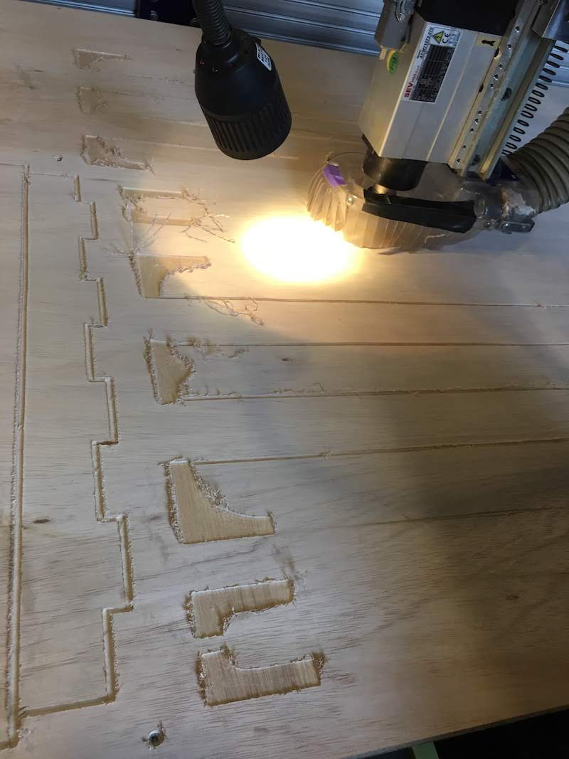
Kerf line on cutout
When starting the pockets and kerfs lines, it looked like the mill was doing the cutout toolpath.
I stopped the milling process and checked my design. I could not find my mistake, so I reexported my pocket and ker toolpaths and restarted the milling process.
I kept having this error. After 1.5 hour I decided I had to continue anyway. After the first pass of the cutout of my top plate the milling continued as expected with the pockets and other kerf lines. It turned out I had selected one cutout line as a kerf line by accidend. This gave the impression of a cutout, but was only a kerf.
Almost fire!
With the stopping of the milling process due to my faulty kerf line I forgot to turn off the spindle.
This was quickly noted by Henk, and within a few seconds I had lifted the spindle and turned off the spindle.
After this error I fortunately never made this mistake again. So I learned my lesson, always press stop button and then turn key to OFF!
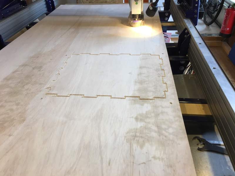
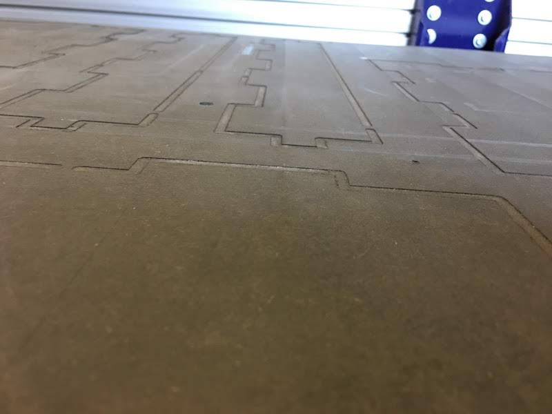
Cutout in sacrificial layer
After my cutout, I noticed I went not only through my material, but also in the sacrifical layer. Much further than anticipated. It turned out I did not measured my wood thickness acurate enough on multiple sides, I only easured it on multiple places on one side. On some parts the wood is 15.37, on the other side more like 15.30. I only measured one side resulting in me thinking my wood was thicker than that is actually was. Next time I will measure my woodthickness on multiple sides and do a test cut to see if my cut out settings are accurate.
Forgot dog-bones
I noticed in time I forgot to put my dog bones in, so after my decorations (pockets and kerfs), I stopped the milling and added the dog-bones to my cutouts saved the new toolpath under a new name with “dog-bones” in it and reloaded the cutout file in the milling software.
Next time I will walk through my checklist more carefully to make sure I did no forget something as important.
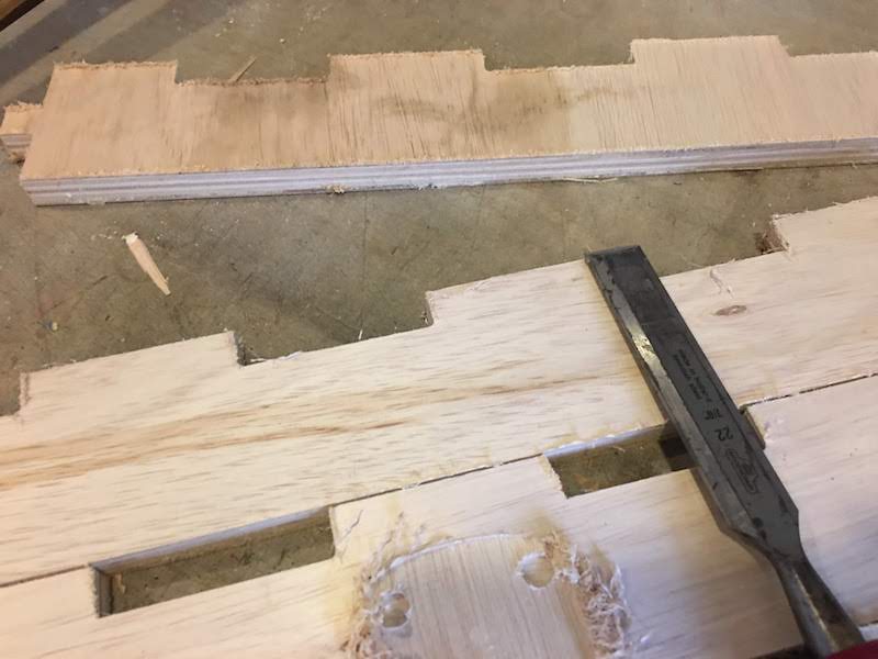
Where are my dog-bones?
Still after the cutout I had to conclude my dog-bones were still missing. Somehow I forgot to check after the cutout and removed my material from the wood before I found out my mistake. Everytime when you change a shape you need to recalculate your toolpath, and maybe I missed this. So I either forgot to recalculate my toolpath, or I loaded the wrong toolpath in the milling software.
I found my error only after removing the material from the table, resulting in having to fix all the corners using a shisel.
Next time I will through away first the wrong toolpath and than recalculate the correct new toolpath.
No offset
The sanding together with the creation of the corners with the shisel took me about 4 hours and would surely be much shorter when I set the correct offset and milled the dog bones.
Using a Shisel with a hamer
When removing our cutout from the wood we used a shisel and a hamer, but Heidi and Anne learned us that especially with this type of material and accuracy it is way better to use only the shisel and slowly remove the tabs by hand.

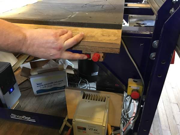
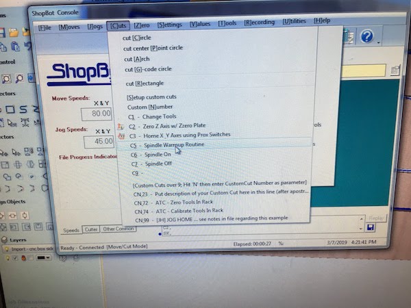
Spindle warmup not working
In the Shopbot software we noticed there was a spindle warmup feature. We tried it, but it turnout our software does not communicate with the spindle speed itself. We need to set the speed manually ourself. So using this feature in the software is not an option for this specific device.
Reflection
I really liked it to create something BIG with the Shopbot. I must say creating something big does add to the complexity with the different software, and the difficulties in all the steps in controlling the Shopbot.
Although I was very carefull in my steps and tried to prevent error, I made many, and noticed I really needed much more time for this assingment, than any other assignment of the previous weeks.
Also looking at the reviews of this week, I noticed that most people either did not finish their work completly or did not finish their documentation. To me this is an indication the assignment is to big to succesfully complete in one week, and I would recommend for next years to stretch it to two weeks. Maybe start with making something small in the first week and making something big the next week.