How to limit yourself while exploring?
1. "3D printing is as good as your design", I remember this while reading an article on 3D Printing by Andreas Bastian.
2. Design to 3D Print or Design, Messup with the GCode and then 3D Print (you can come up with your own).
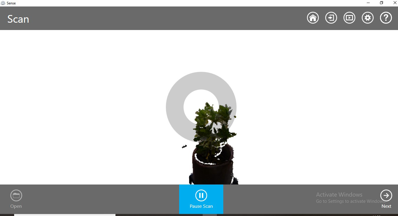
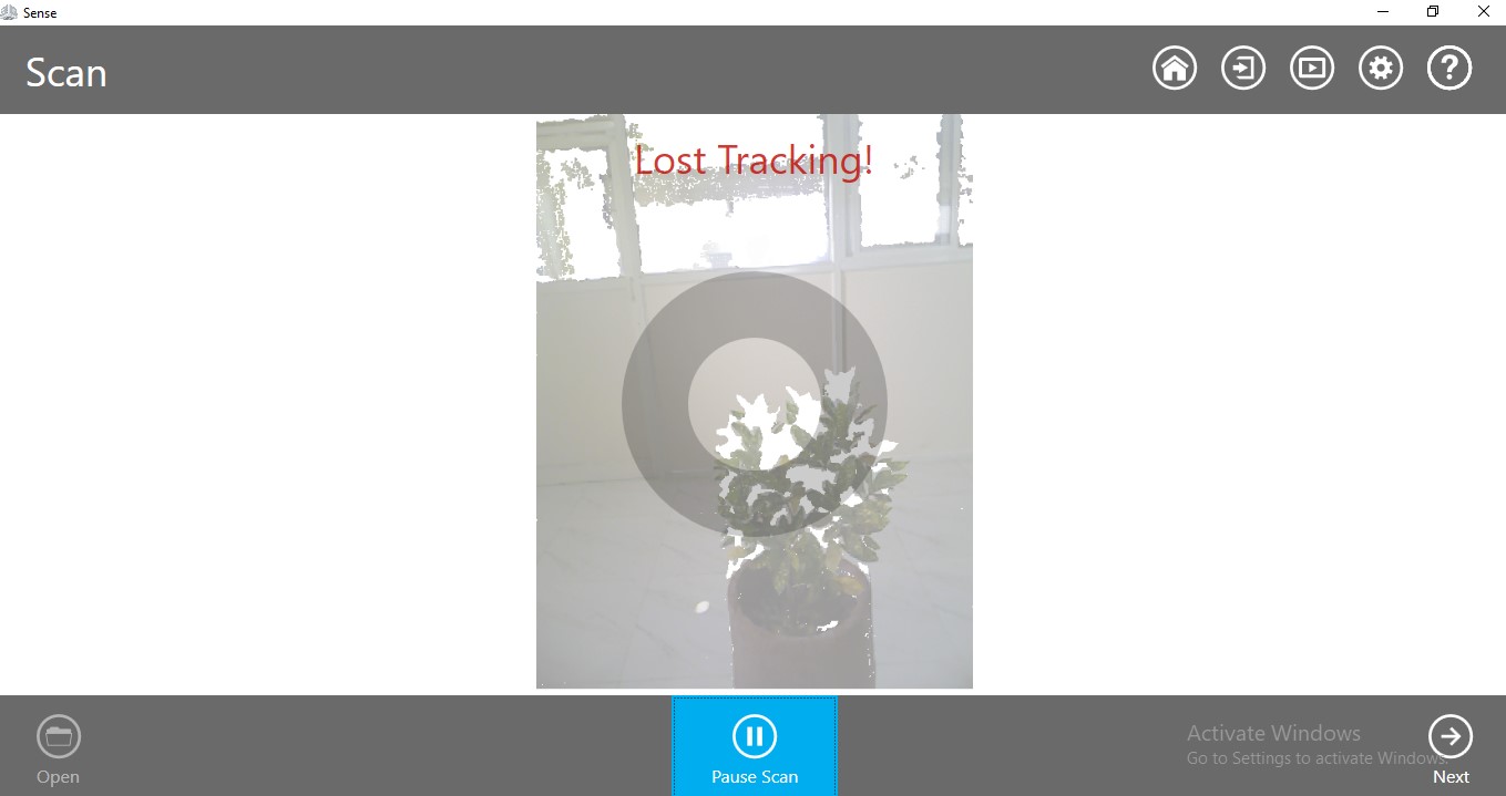
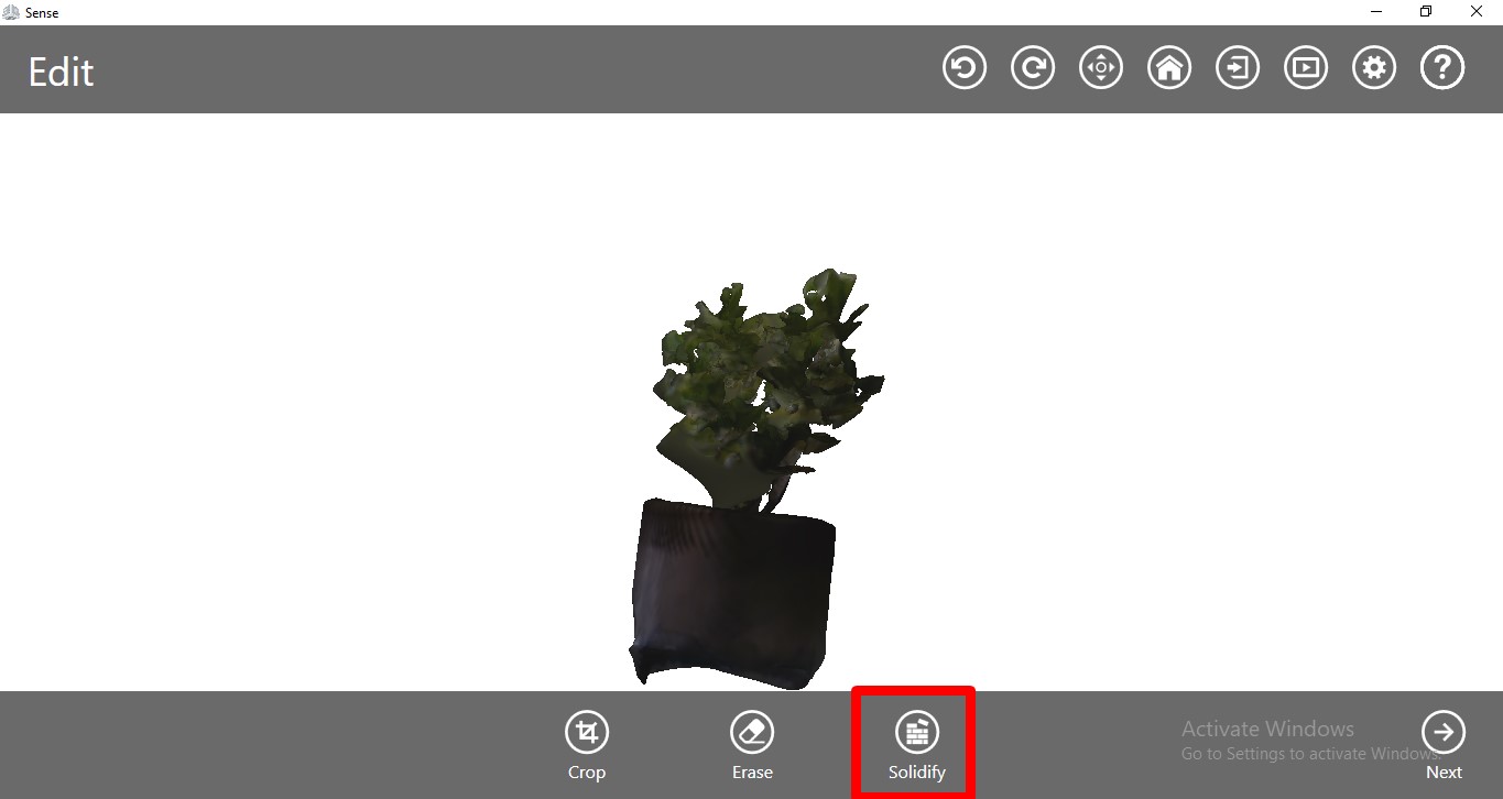
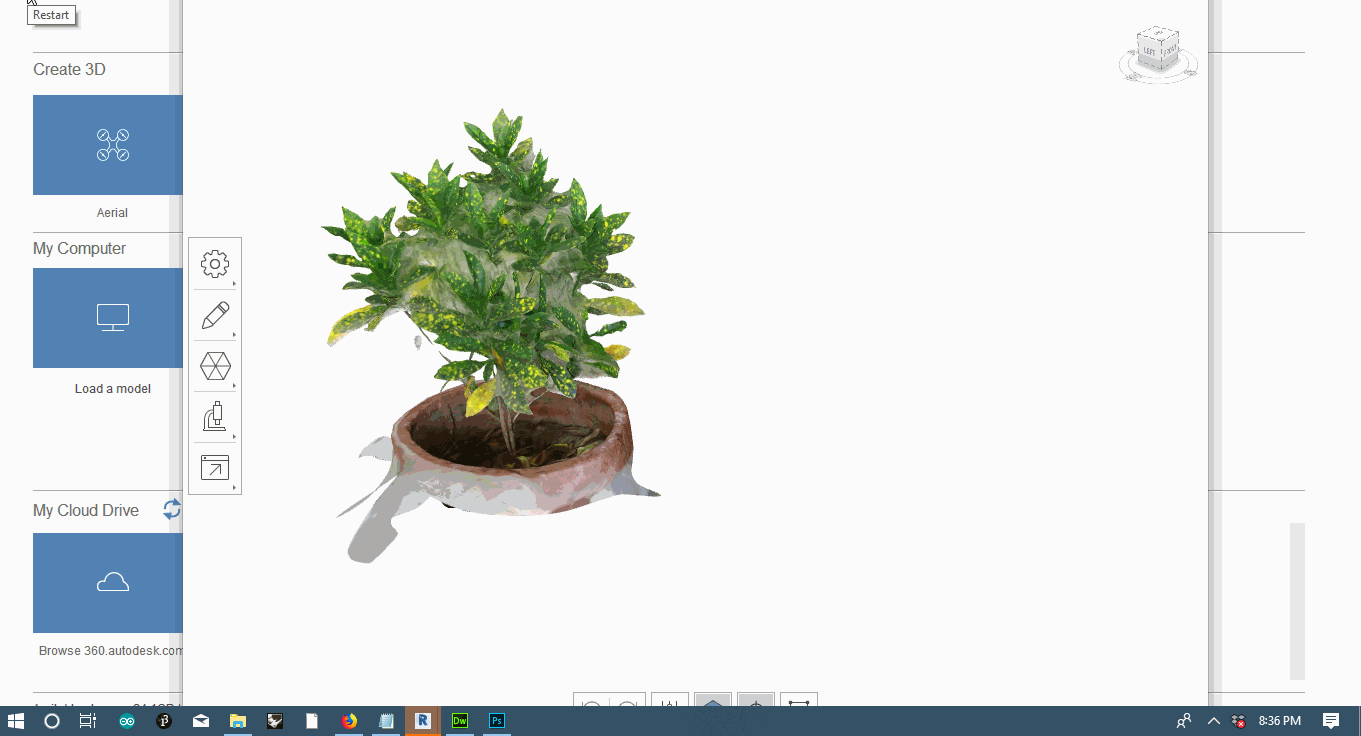
3. 3D scanning definitely requires a setup to be get better scans, be it photogrammetry or 3D scanners
3D Printing
Brief Overview
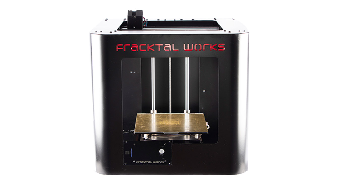
Afer finishing Week 4, whose main focus was on subtractive processes, this week focusses on additive processes and more so on 3D printing. This week foresees designs that could not be made using subtractive process like Laser Cutting but rather only through additive process like 3D Printing. While digging deeper into 3D printing, it could also be noticed how various kind of 3D printers work with different materials. A common observation is that 3D printer wastes way less material as compares to subtractive process like Laser Cutting. Since, I already had some experience with 3D Printing(FDM) before, while designing my 3D Printer at Fab Lab CEPT. At our FabLab in Vigyan Ashram, Pune we used Fracktal Works 3D Printer named Julia, it is a FDM (Fused-Deposition Molding) printer. Some of the key things of this printer are as follows:
1. Built volume is limited to 200mmx200mmx200mm.
2. It takes only STL and G-code formats
3. Its a single extruder 3D Printer esentially a FDM printer.
4. The layer height varies from 60-300 microns.
5. The slicing software associated with it to assist in slicing and generating Gcode is called Fracktory.
With my past experience I have found that FDM printers are good for quick protyping and I have had a disliking towards them for their lack of precision and due to the presence of layers. Though it can be removed using post prcessing techniques. Another factor being that a FDM printer has the ability to print only a certain set of geometry very quickly when compared to a SLA or SLA printer. The addition of supports increases the print time. Hence, for this week's assignment I used PLA(Polylactic Acid, a biodegradable plastic) as a filament and rather than going for 3D printing some fancy things I tried to use a slightly different approach. PLA is not very flexible in nature and I wanted to 3D print something that can exhibit some flexibility. On the other hand I wanted to play around with GCode to see how the the machine responds to it.
Group Assignment
Before starting out to 3D model our designs, a mandatory assignment had to be finished along with other batchmates, in order to determine various parameters like how thin and fine can be print, how much overhang can we give and how much infill density we need to name a few. These parameters will help us while designing and they kind of set a limit for us.
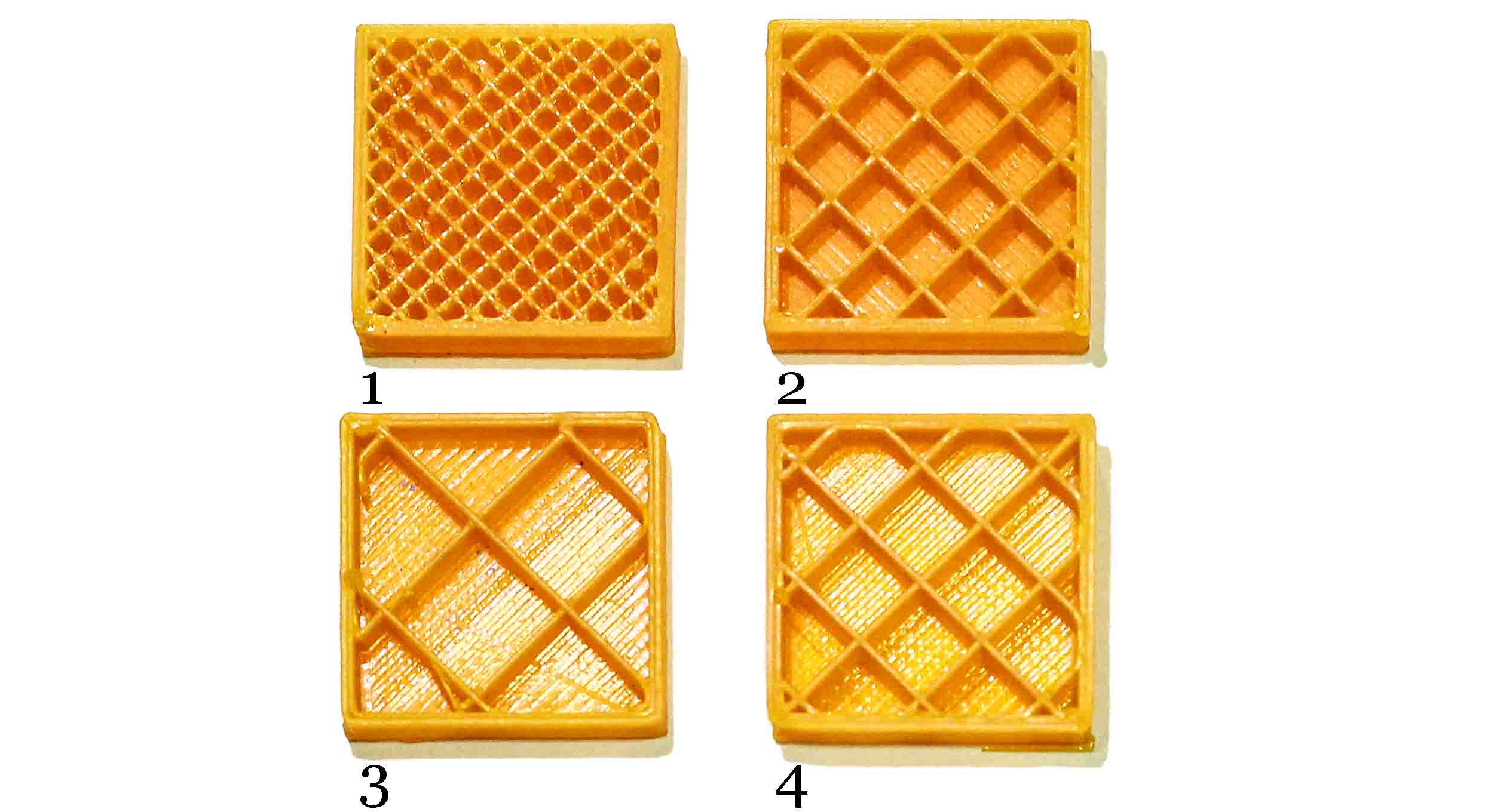
Firstly, we wanted to see how various settings work out starting from Ultra, High, Normal and Fast quality i.e an Infill test. The obvious observation was the amount of time taken to print them. Also, the density of the internal lattice also decreases from Ultra to Fast. One can also notice a difference in the surface finish. The surface feels more smooth when its printed using Ultra settings. Hence, this also concludes that if we want to just test our designs, the recommended settings start with Normal settings unless the design requires joints between objects, in this case Ultra settings are needed.
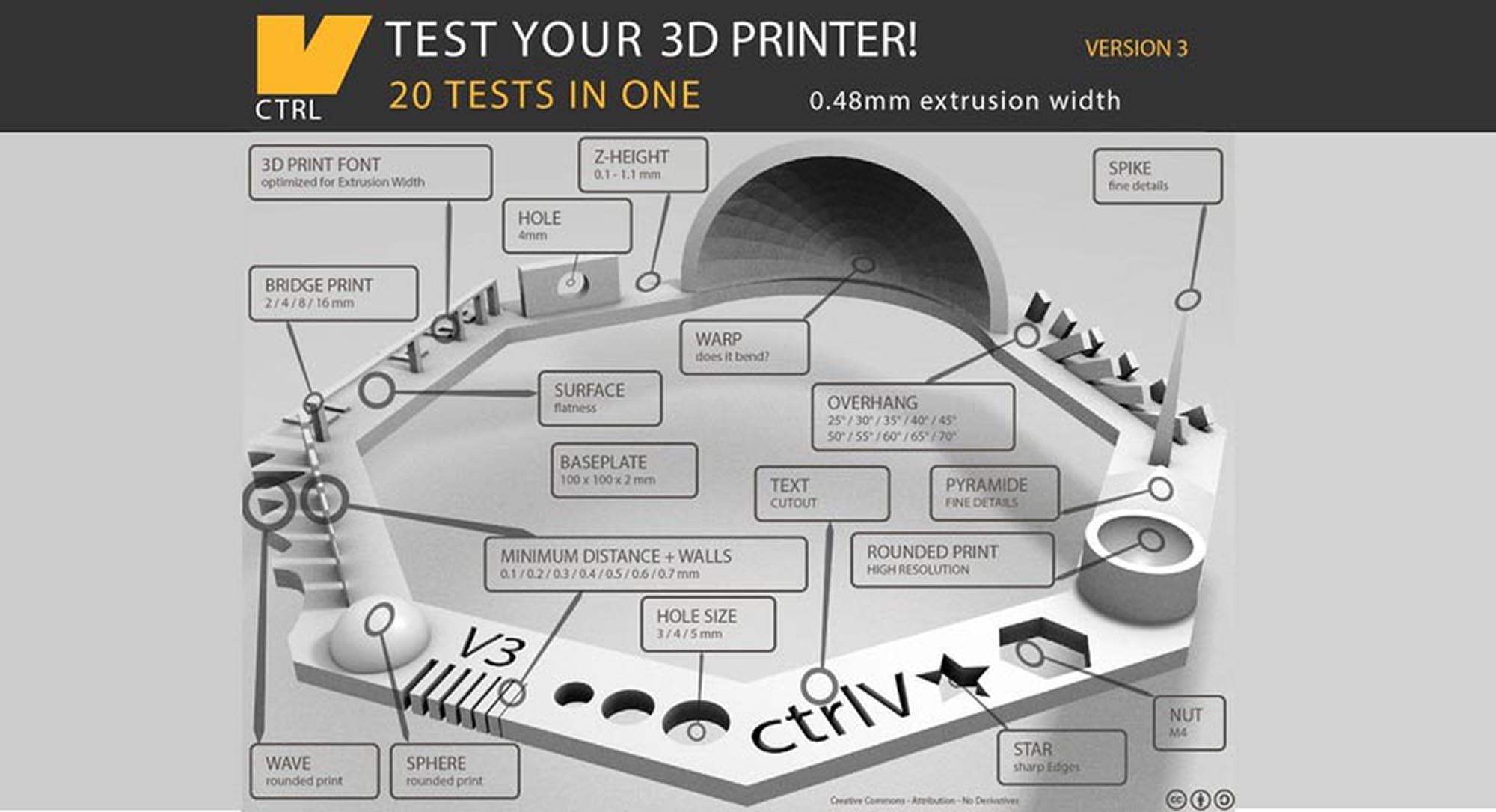
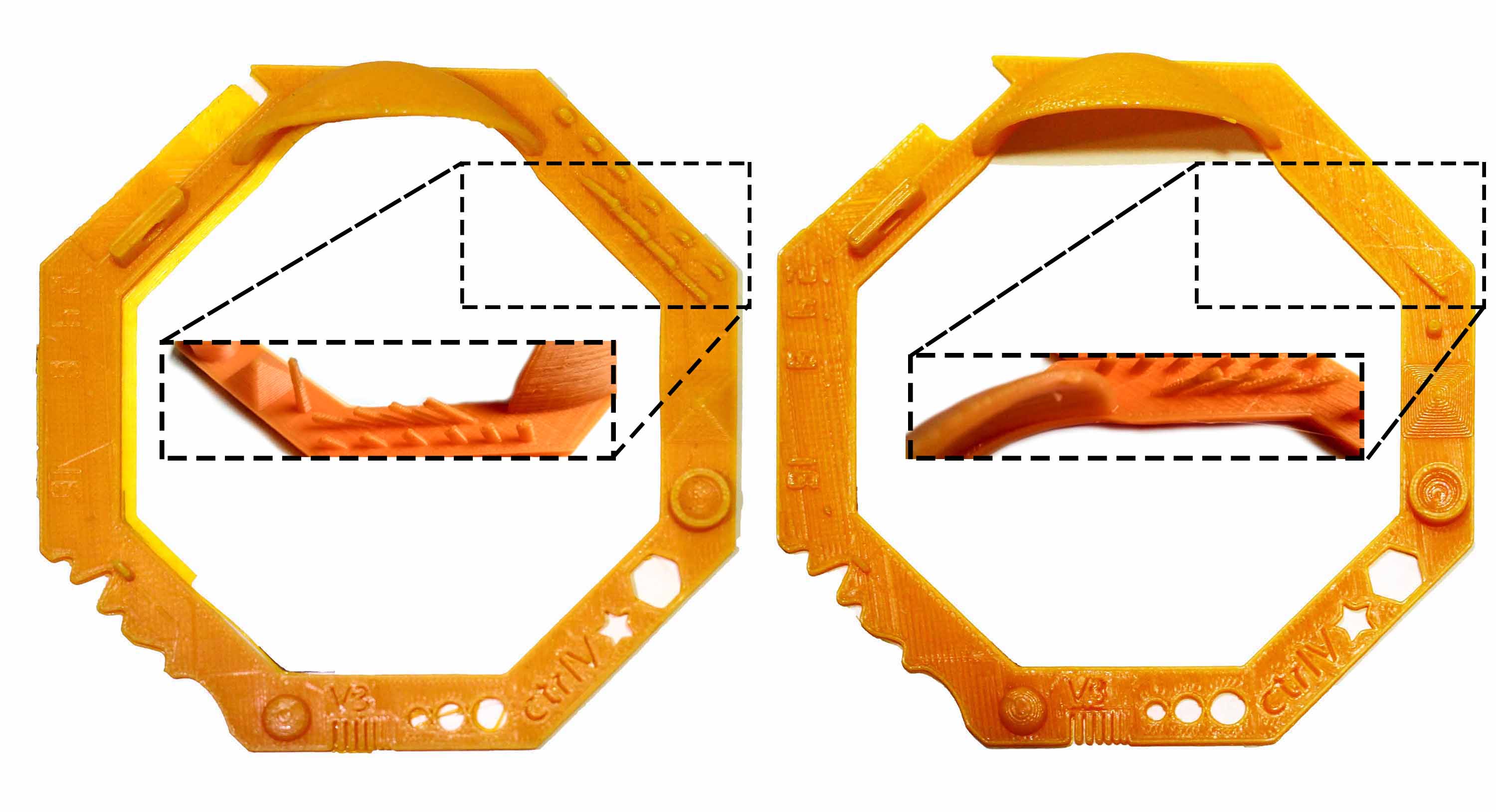
Our group decided to take a 3D printer Test v3 file by ctrlV(illustration 2 above) that involves 20 tests in one go. We used fast as well as normal quality settings to 3D print the file. While using the fast settings our 3D printer couldn't print 25 and 30 degree angles in the overhang section of the file. When we used the normal settings, there wasn't any discrepency. The reason attributed to this is because of the time it takes for varies layers to cool down and fuse together.
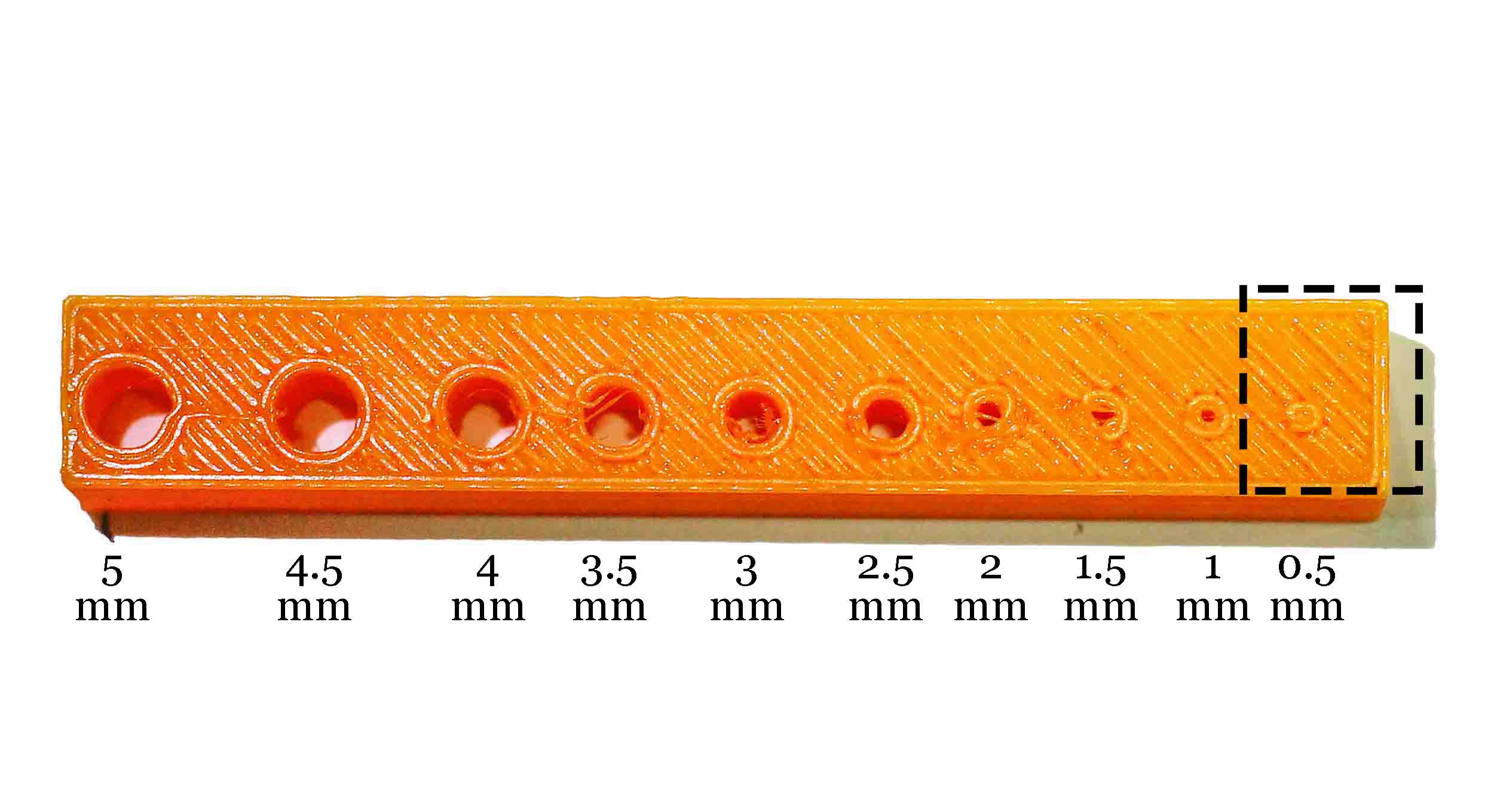
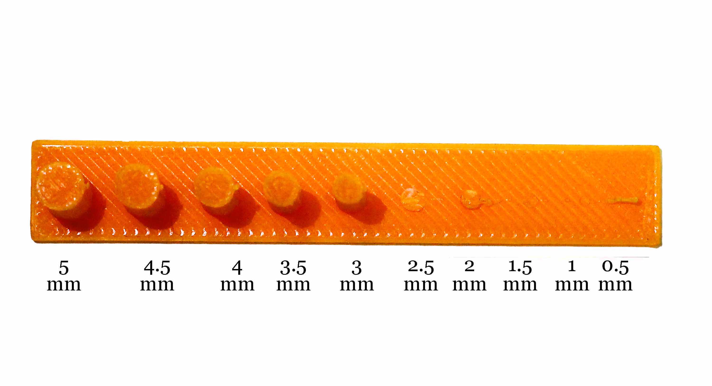
The last leg of this assignment, a hole test involved creating holes of varying diameters to see how small the 3D printer could print. We used normal quality settings to 3D print. We observed that the 0.5 mm hole didn't print well. To complement this test we also did a resoluton test firstly, to see if these holes can fit in cyclinders of similiar diameter (which they didn't) and also to check their rigidity. We concluded that rigidity is directly proportional to thickness(here diameter).
Bending
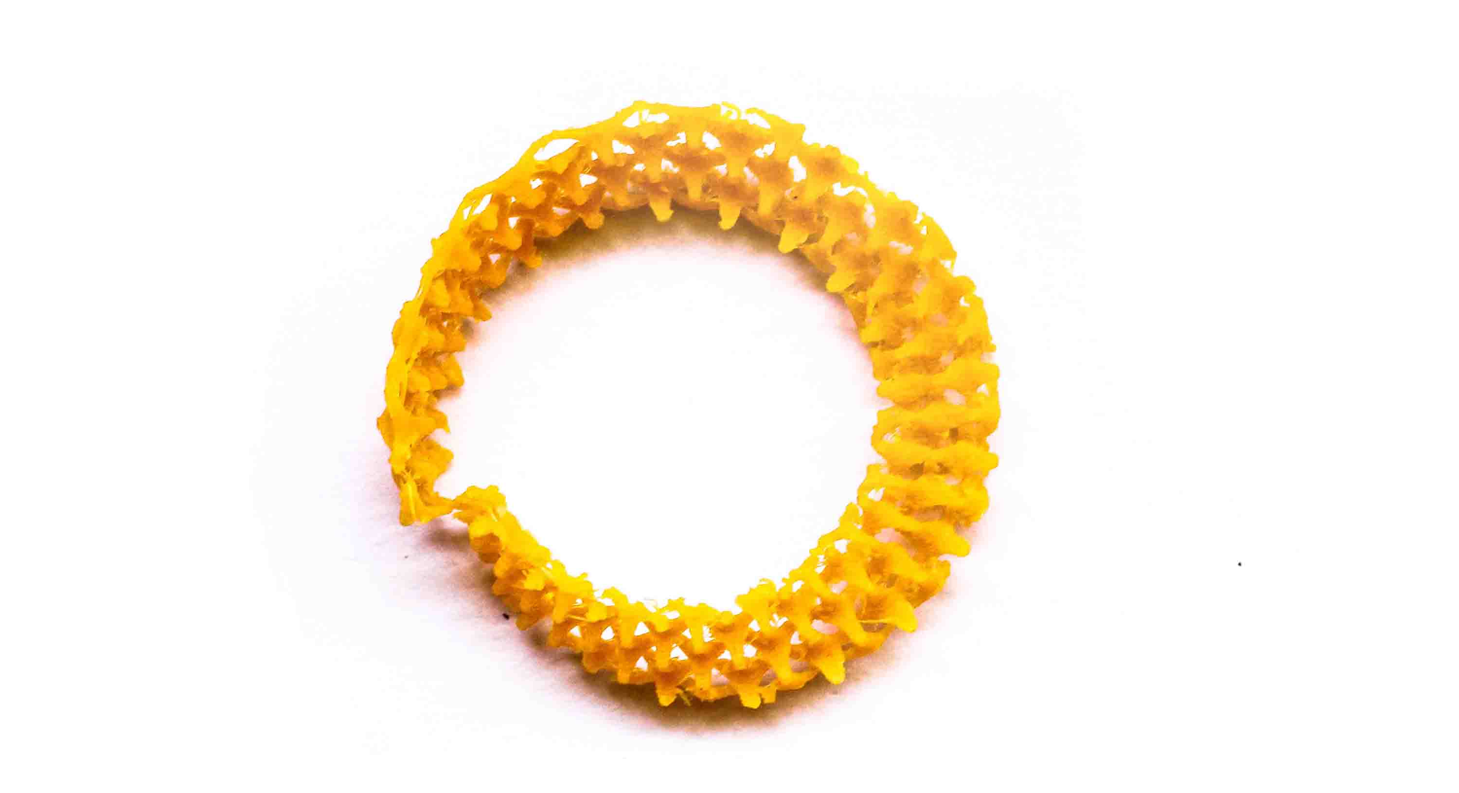
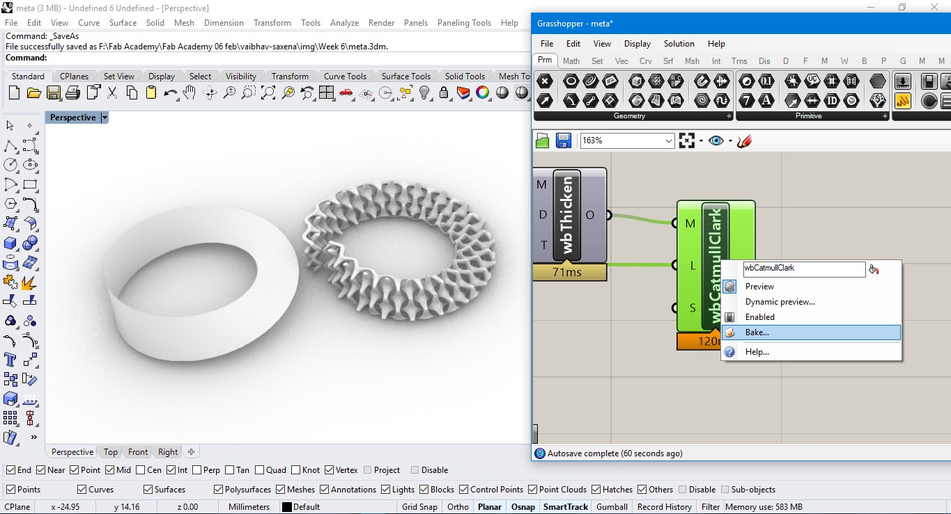
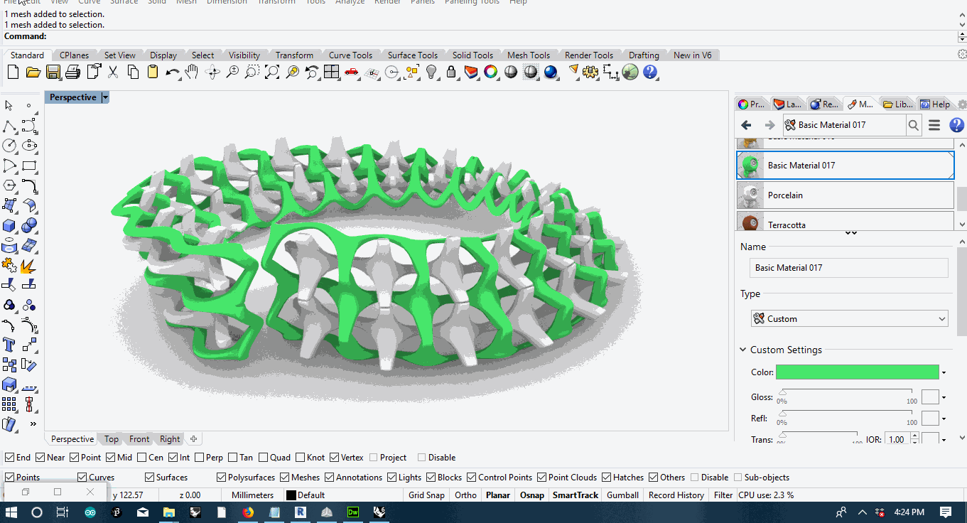
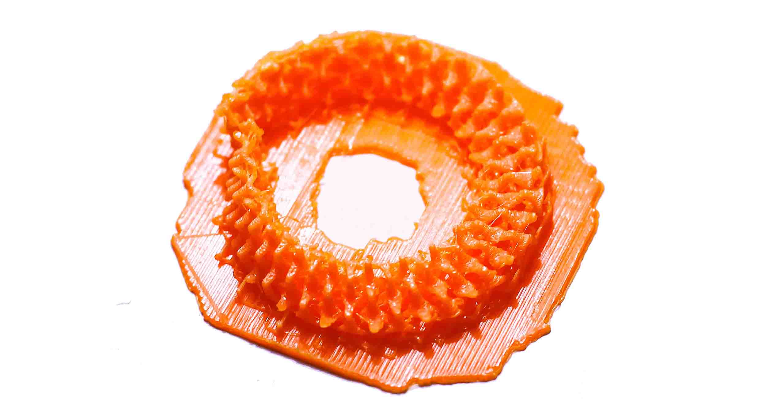
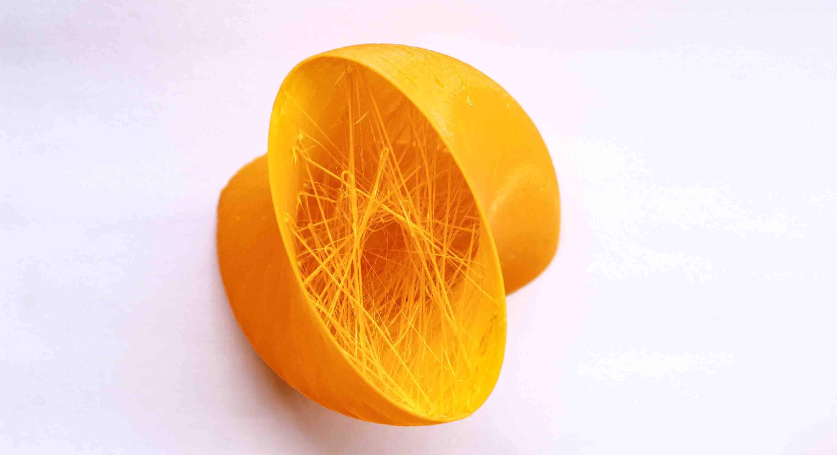
To try out something new, I started with 3D modelling in an attempt to work towards the concept of metamaterials to explore if a 3D printed object using PLA could be made flexible or not. Metamaterials – a type of engineered material defined by its 3D internal structure rather than what substance it is made of have displayed characteristics that natural materials cannot especially shape morphing. I was inspired by Erwin Hauer's installations and made a small script using Grasshopper mimicing the same. I then applied this pattern on a very simple half loop surface called mobius strip. Since we were told by our lab instructrs initially, to limit the size of our 3D prints upto few centimeters(5 cm or less), hence I chose to print a smaller one.
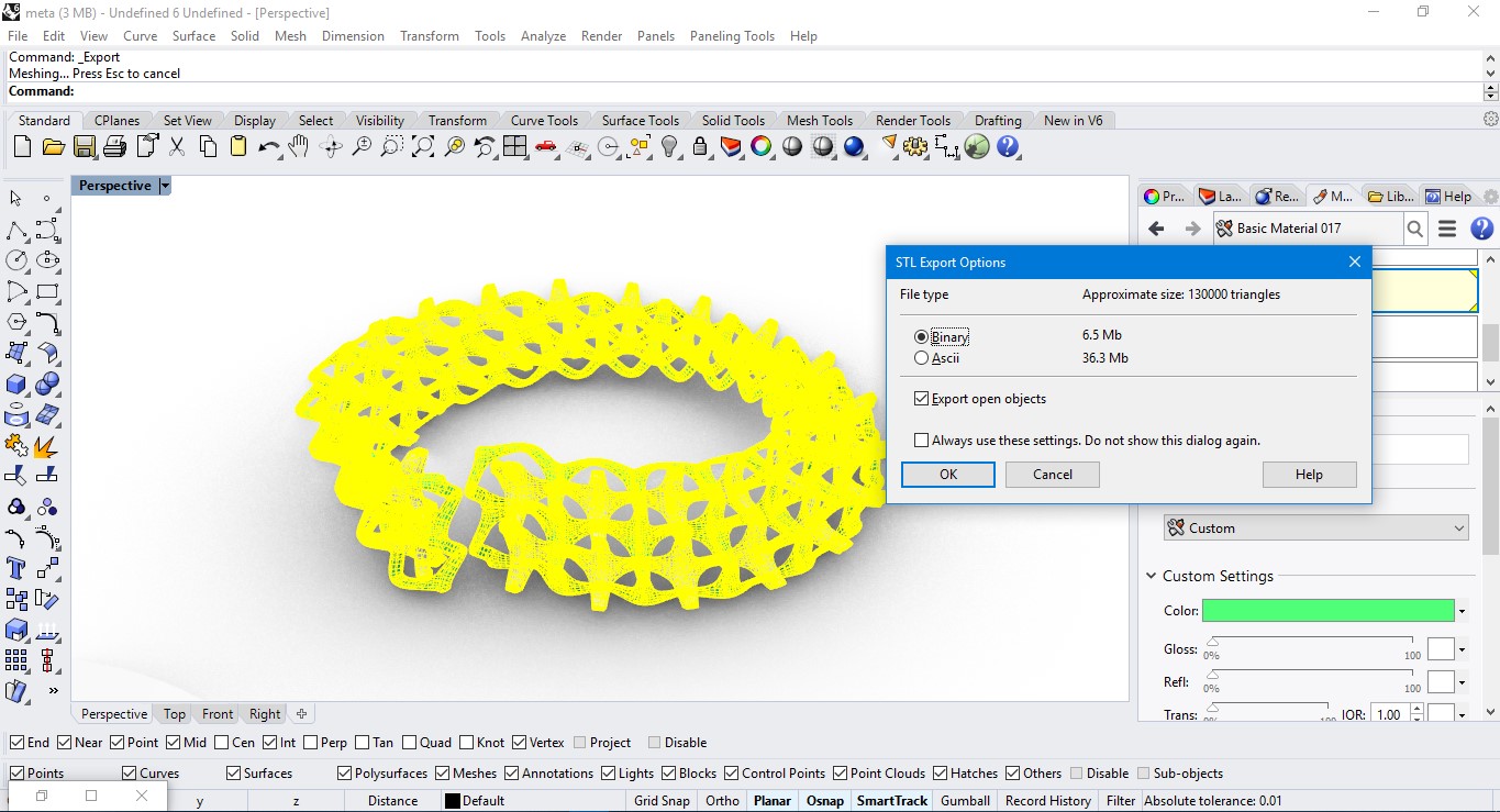
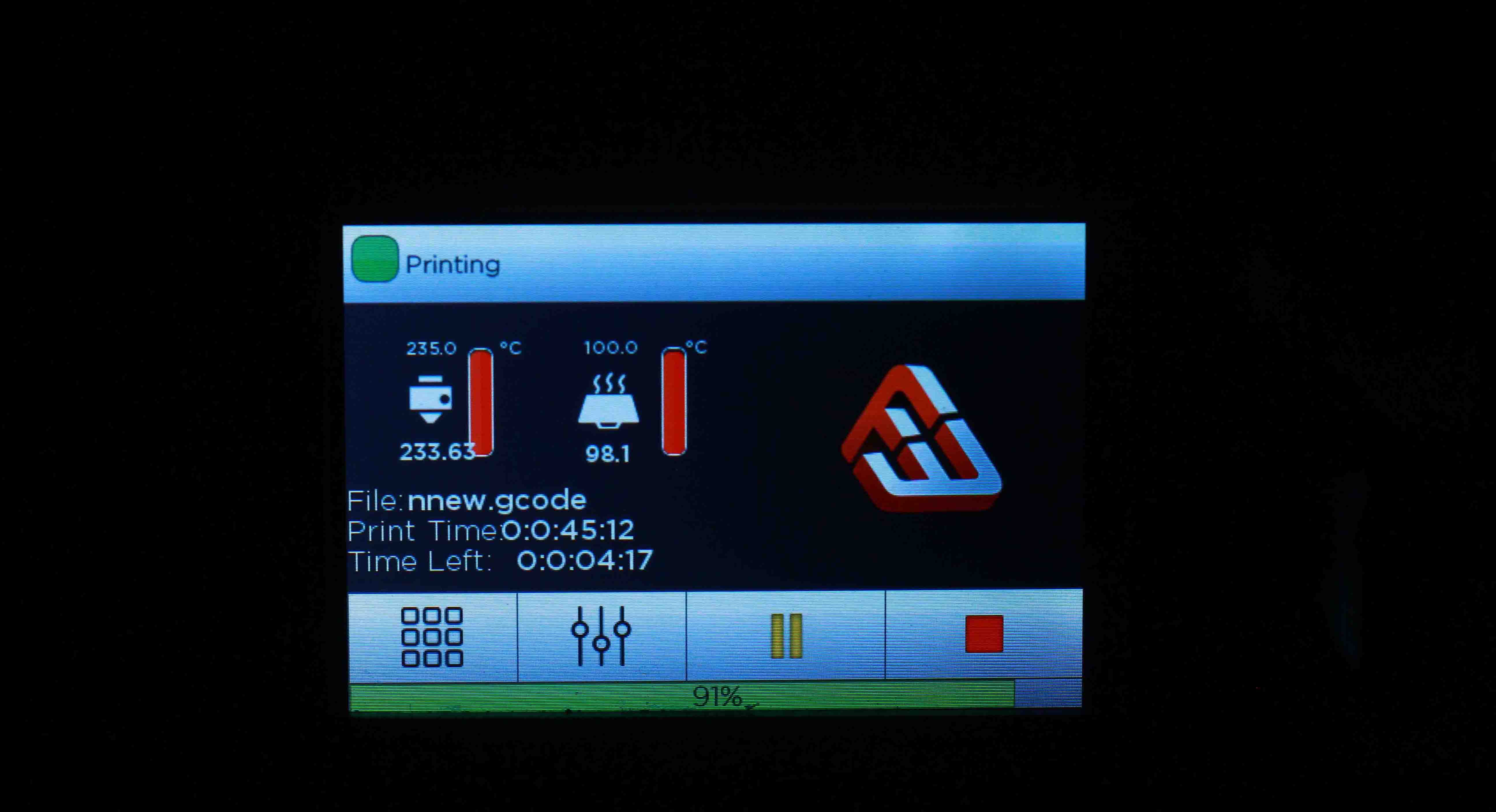
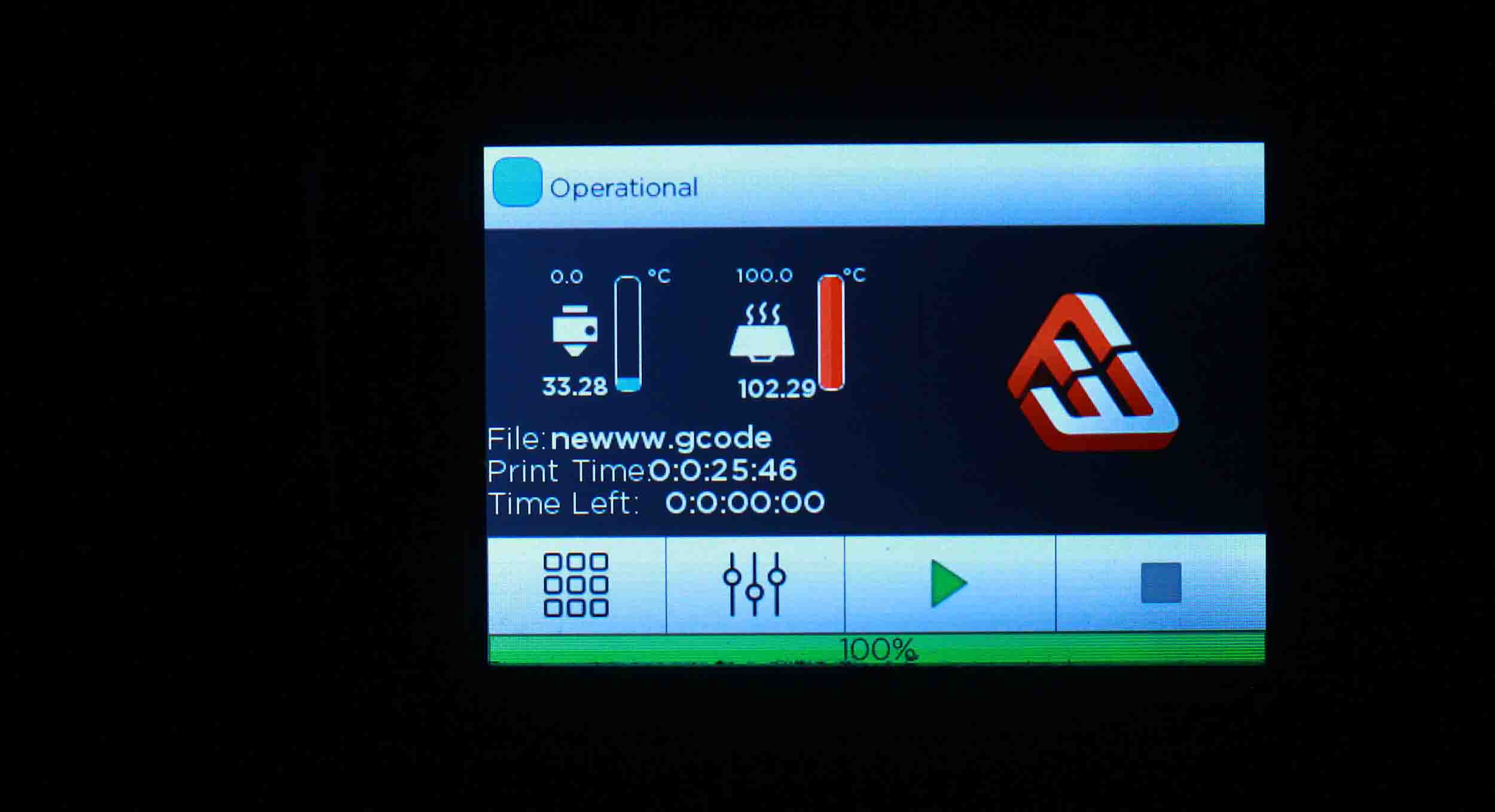
Once the scripting was finished in Grasshopper and Rhinoceros, it gives you an option to export the file in .stl format to 3D print. The export options displays the total number of triangles and also the option to export in either Binary format or ASCII format. For my first print, I chose "Ultra" quality 3D print option. Because of the nature of the model, it generated lot of supports. It took total of 90 minutes to print. One thing to notice here is the time displayed on software for 3D printing is less as compared to the actual time taken. This extra time is attributed to raise the temperature of the bed and the extruder.The following were the settings used in the print:
1. Extruder Temperature 230° celcius
2. Bed Temperature 100° celcius
3. Shell Thickness 0.8 mm
Download the file here
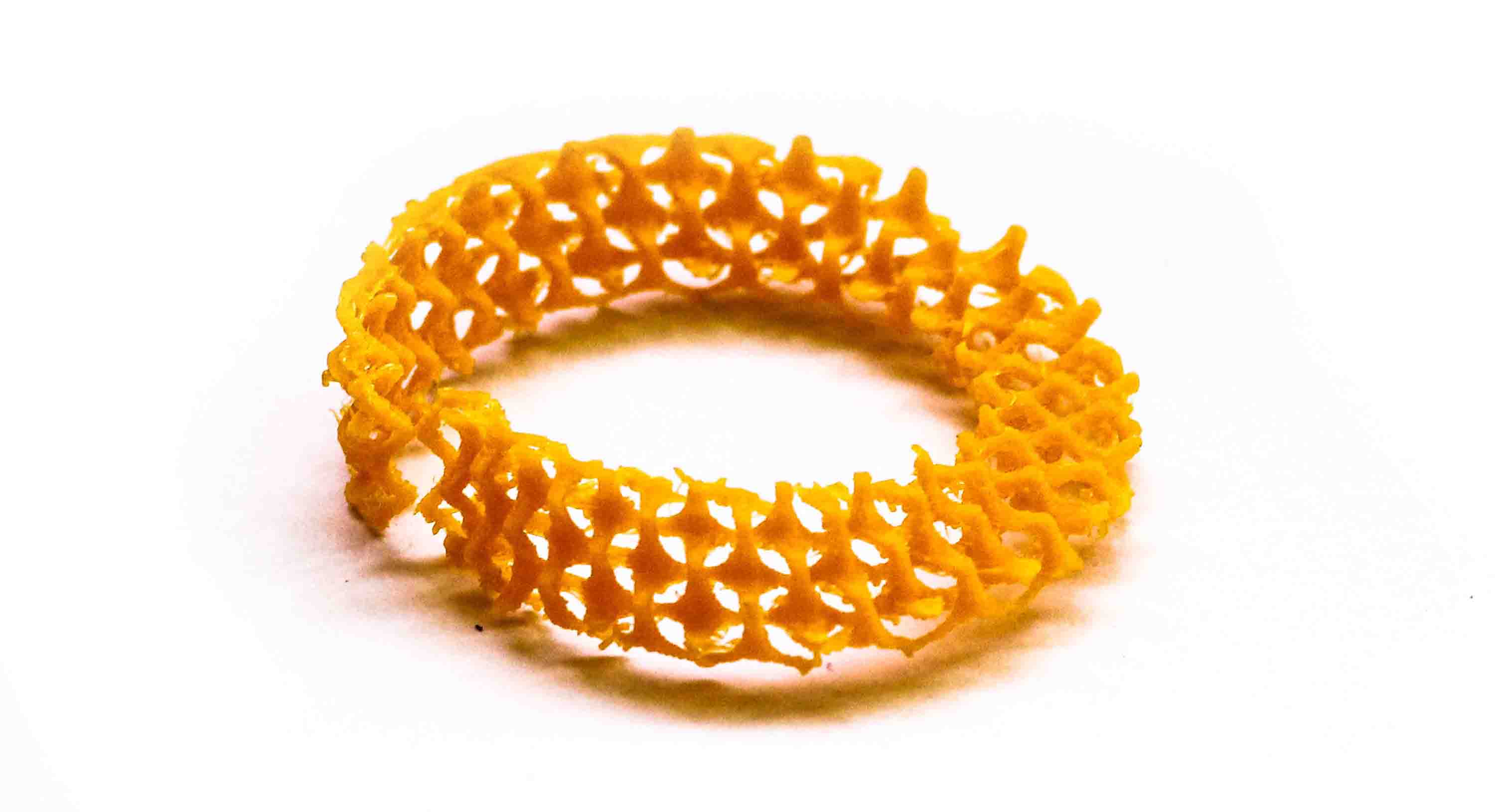
Weaving
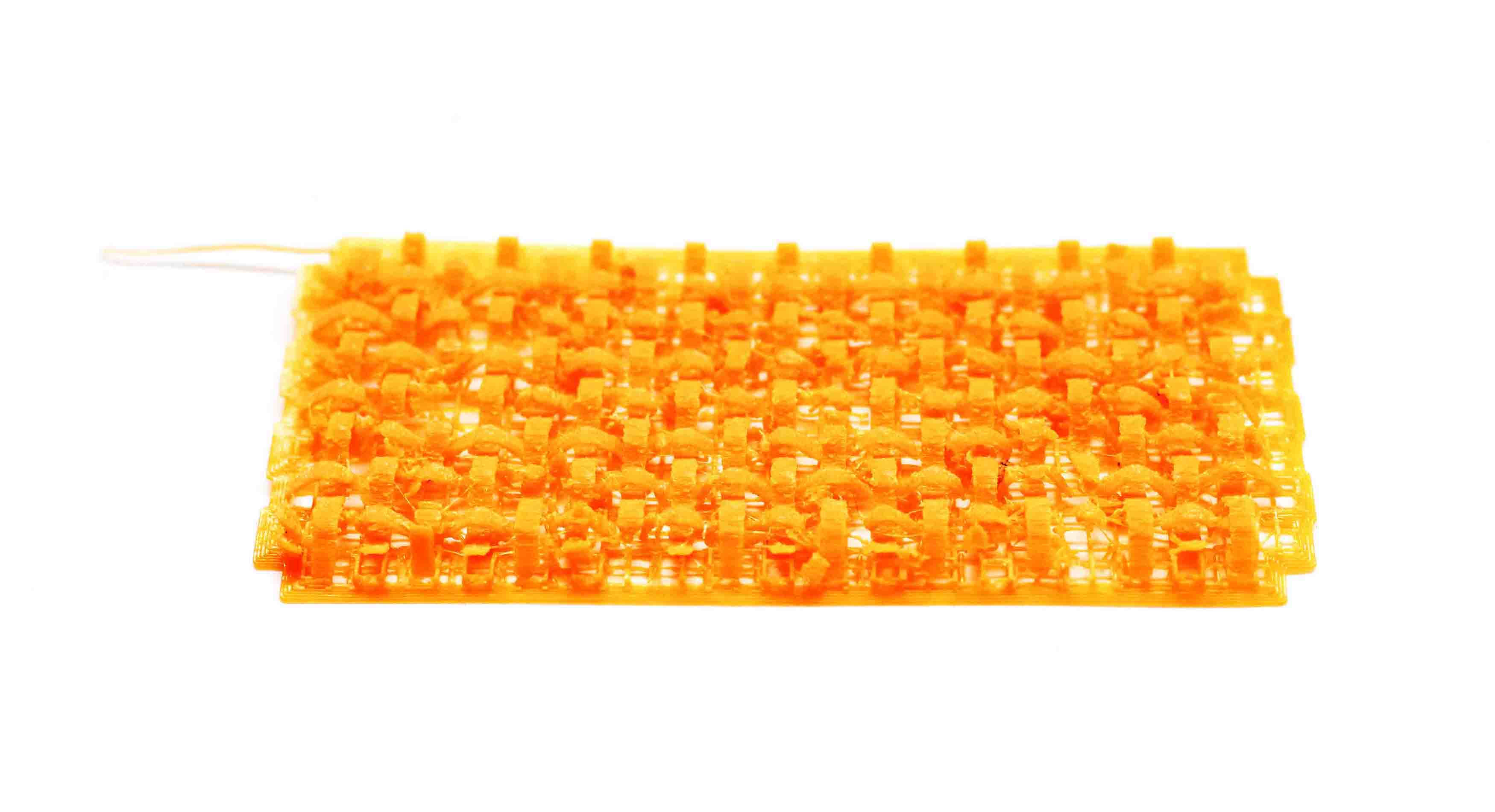
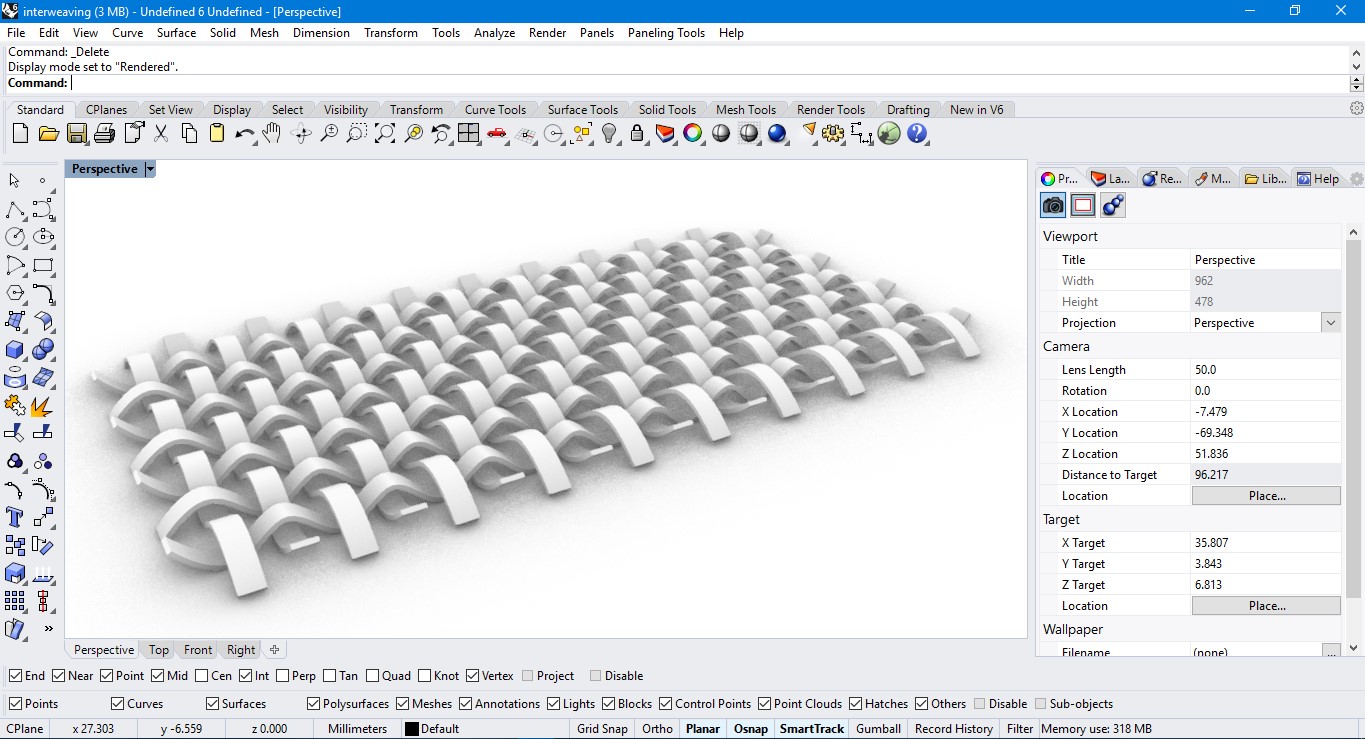
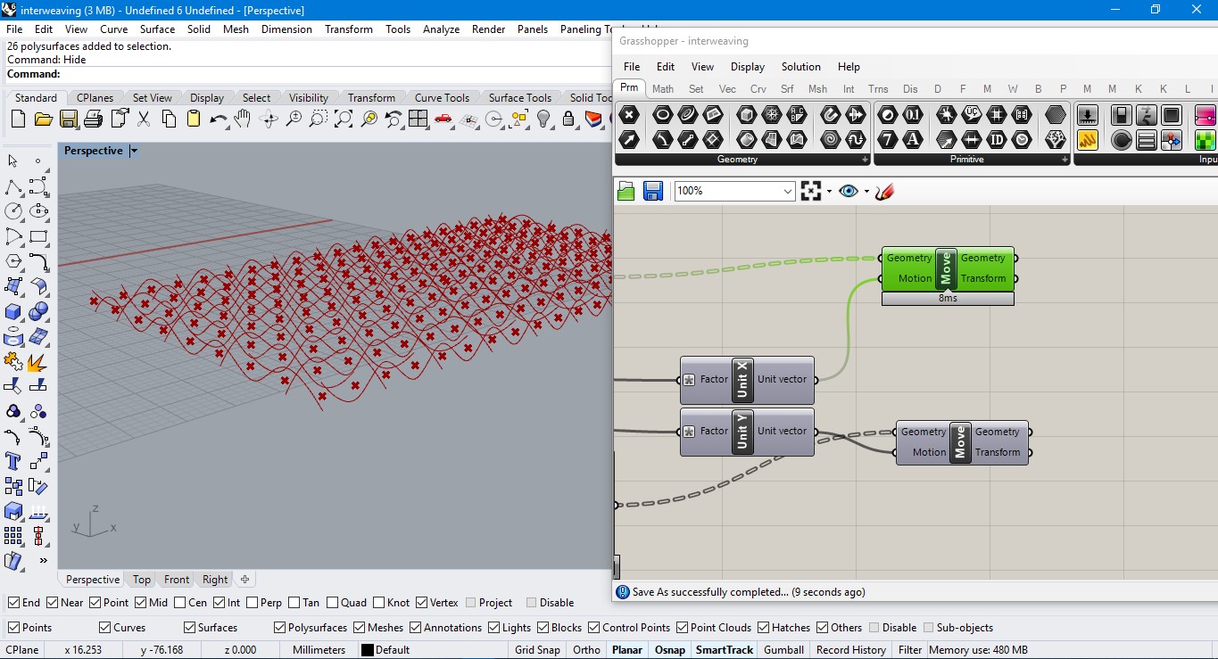
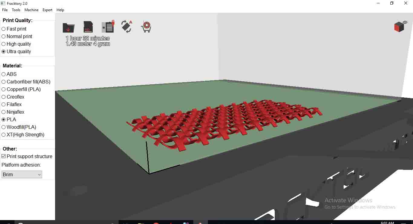
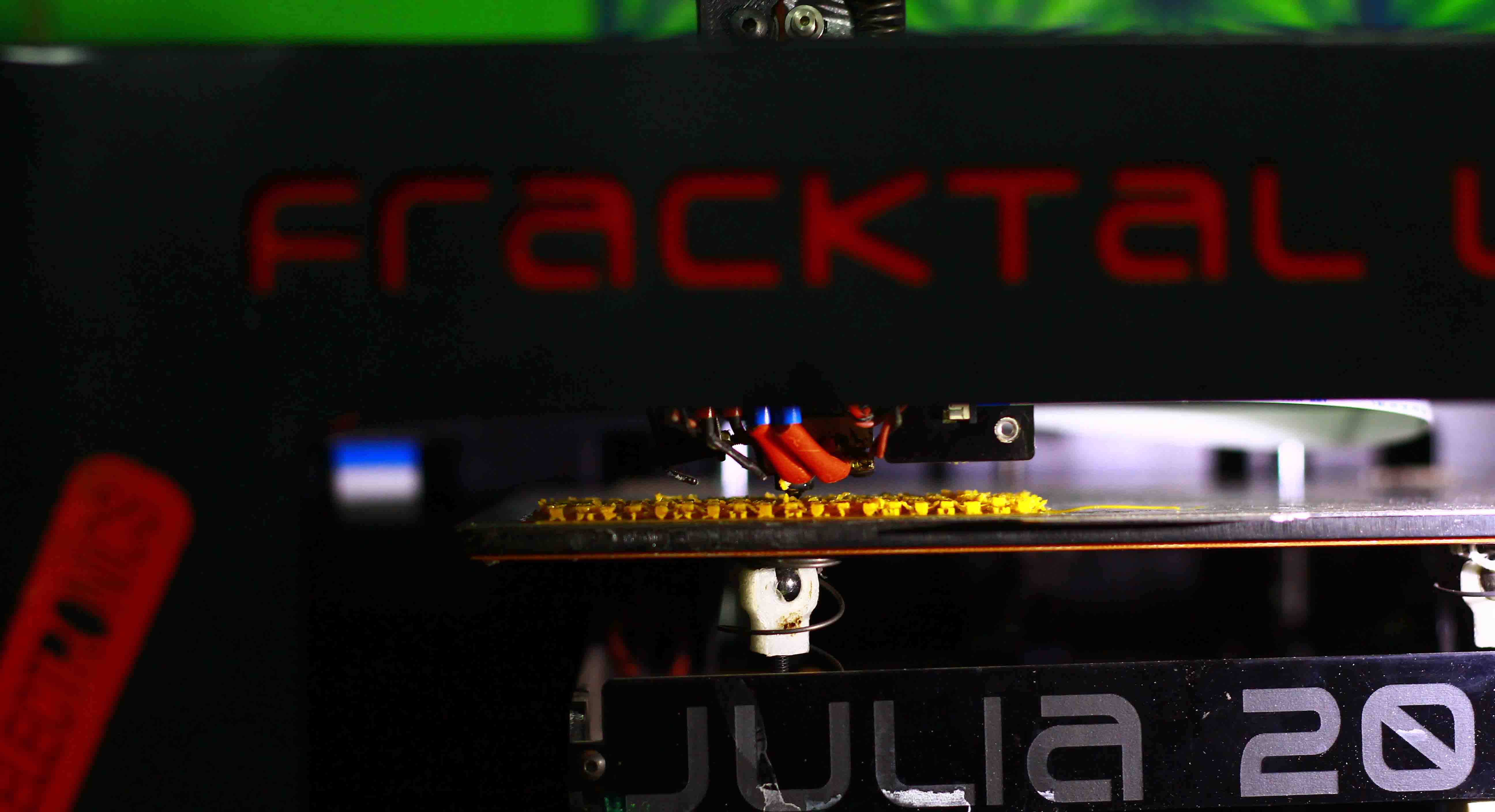
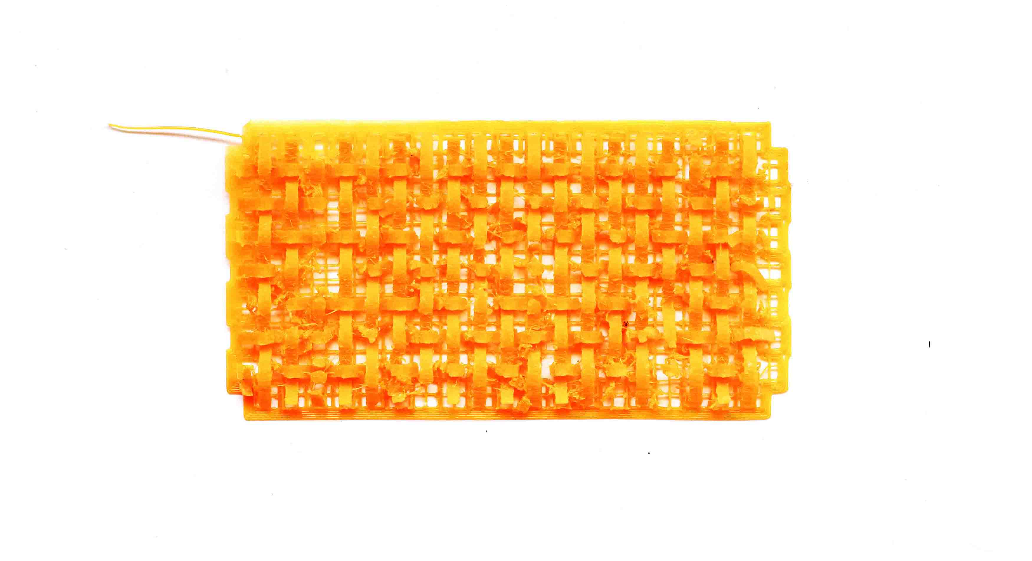
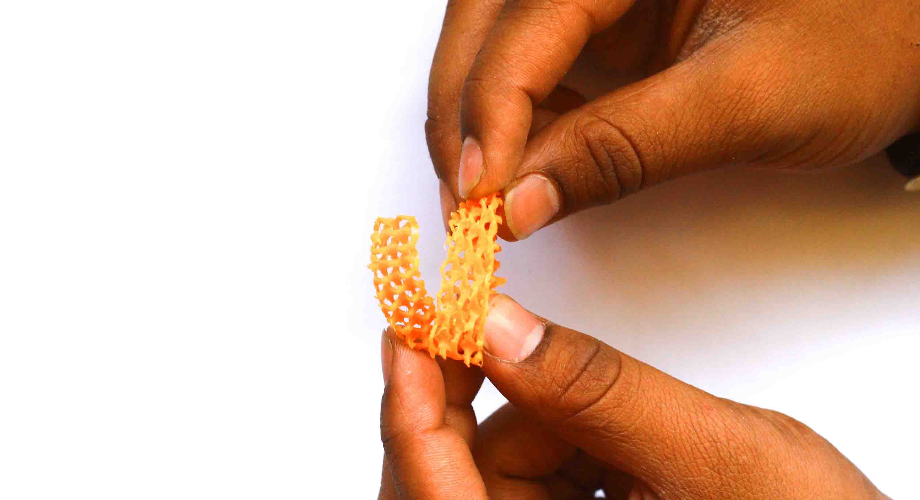
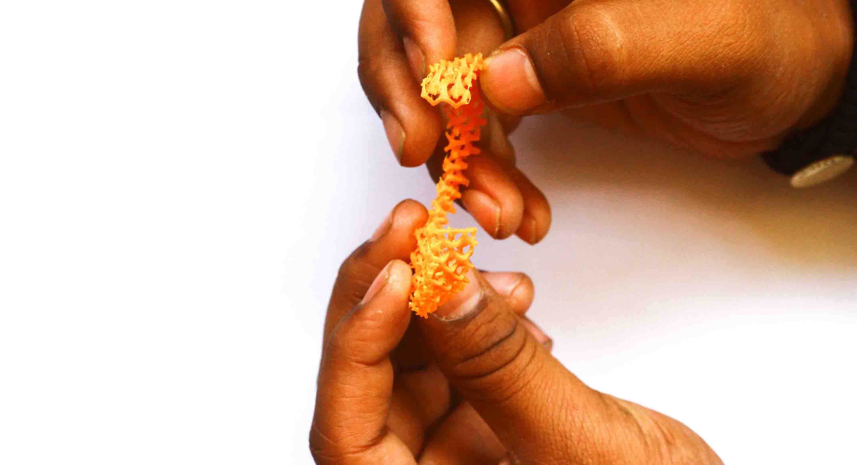
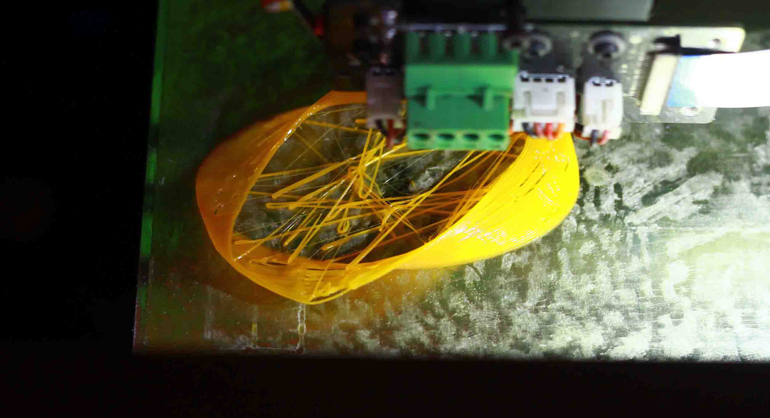
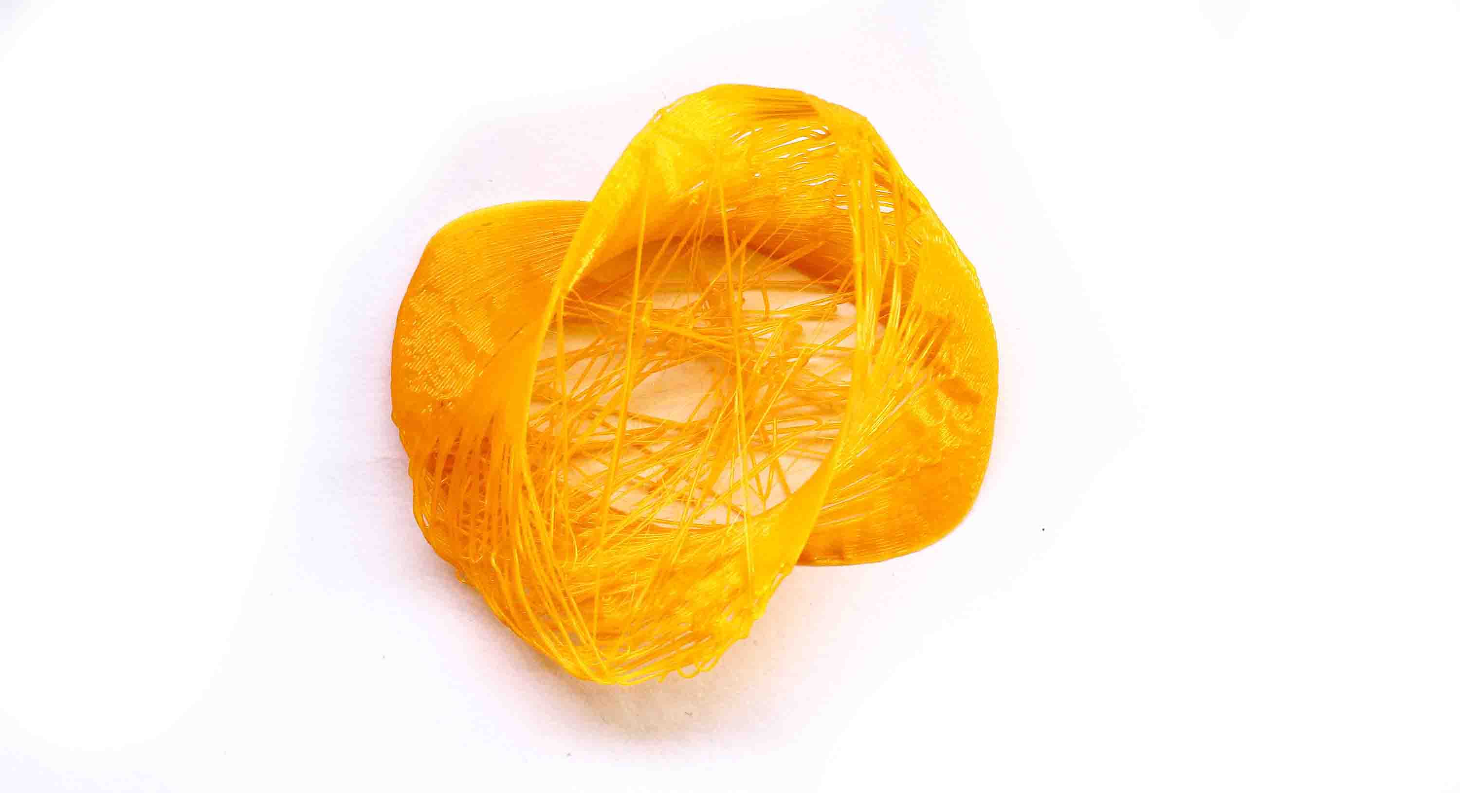
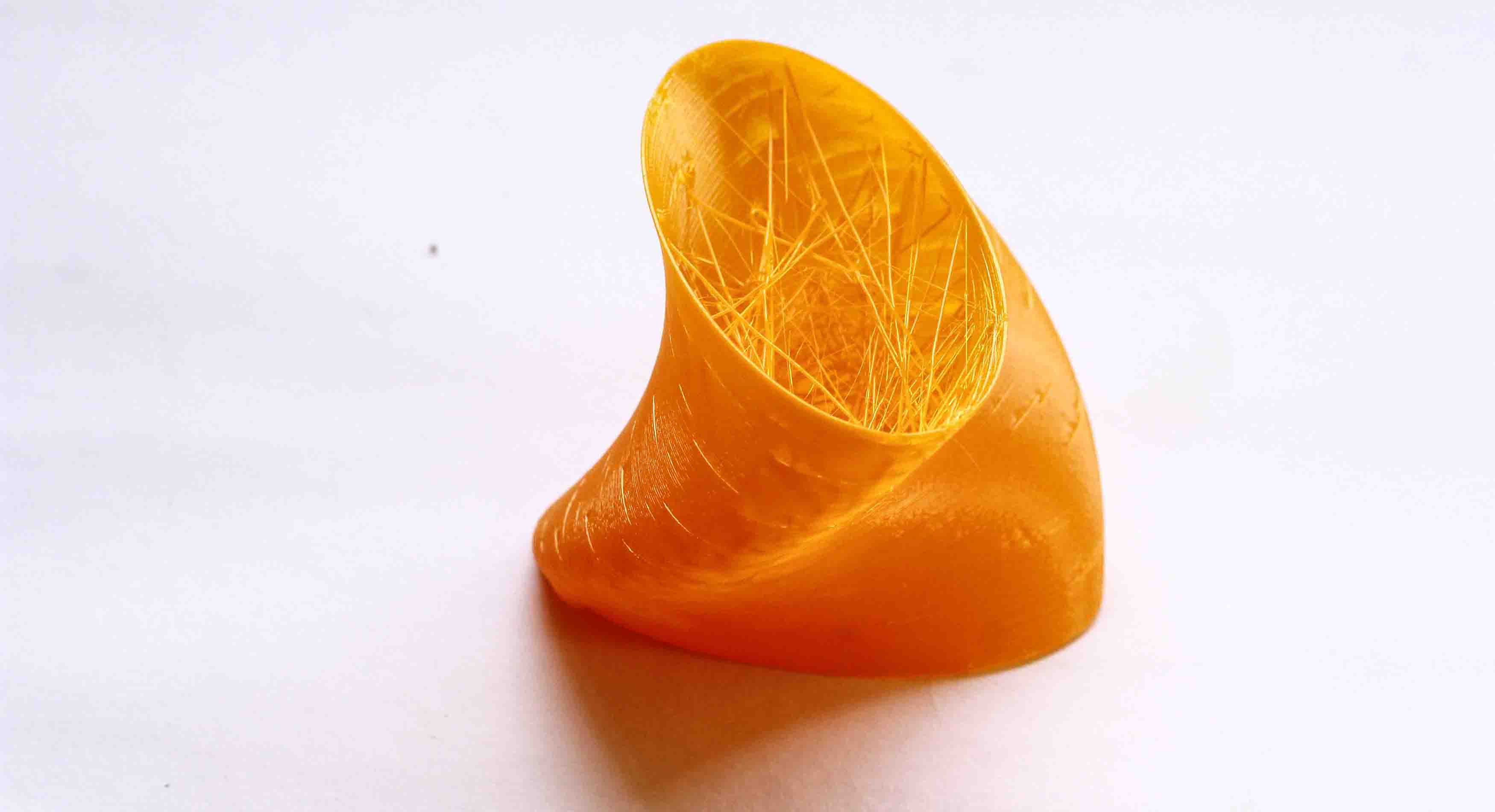
I was really excited after seeing the results of my first 3D print, hence I went ahead for another 3D print based on similar lines. I tried to mimic the interweaving pattern of the textile, thinking that I would be able to push the properties of PLA by bending the 3D printed object solely based on its design. I again opted for Grasshopper to code a pattern. The pattern is simple in logic with pushing alternative points up and down by a distance and creating a curve by interpolating through the points. The curve can be given a thickness and a width. Since I wanted the pattern to be as thin as possible, I gave a thickness of 0.5 mm. Also, the distance between the cross strips was 2 mm, to provide the essential gap to bend.
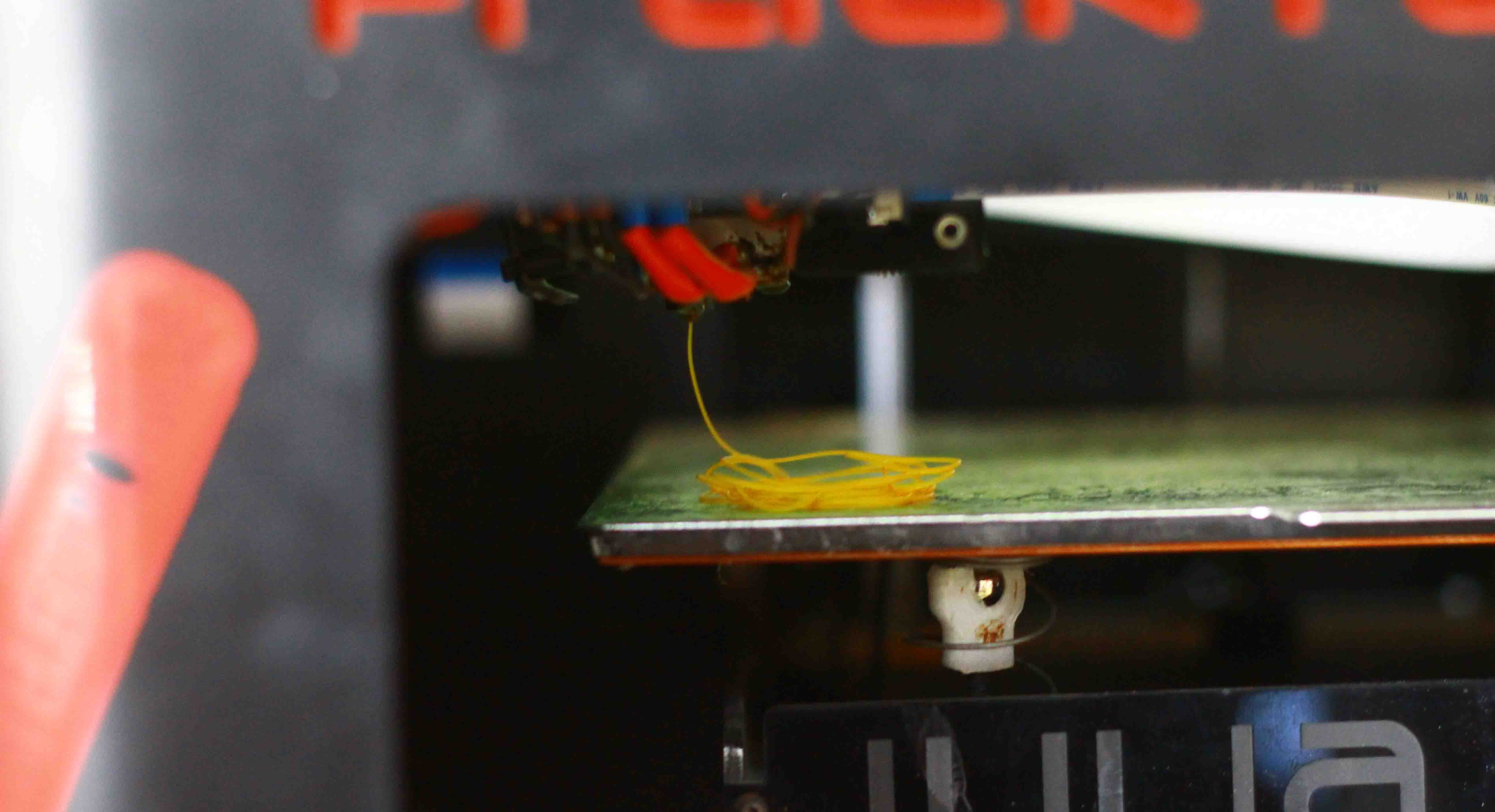
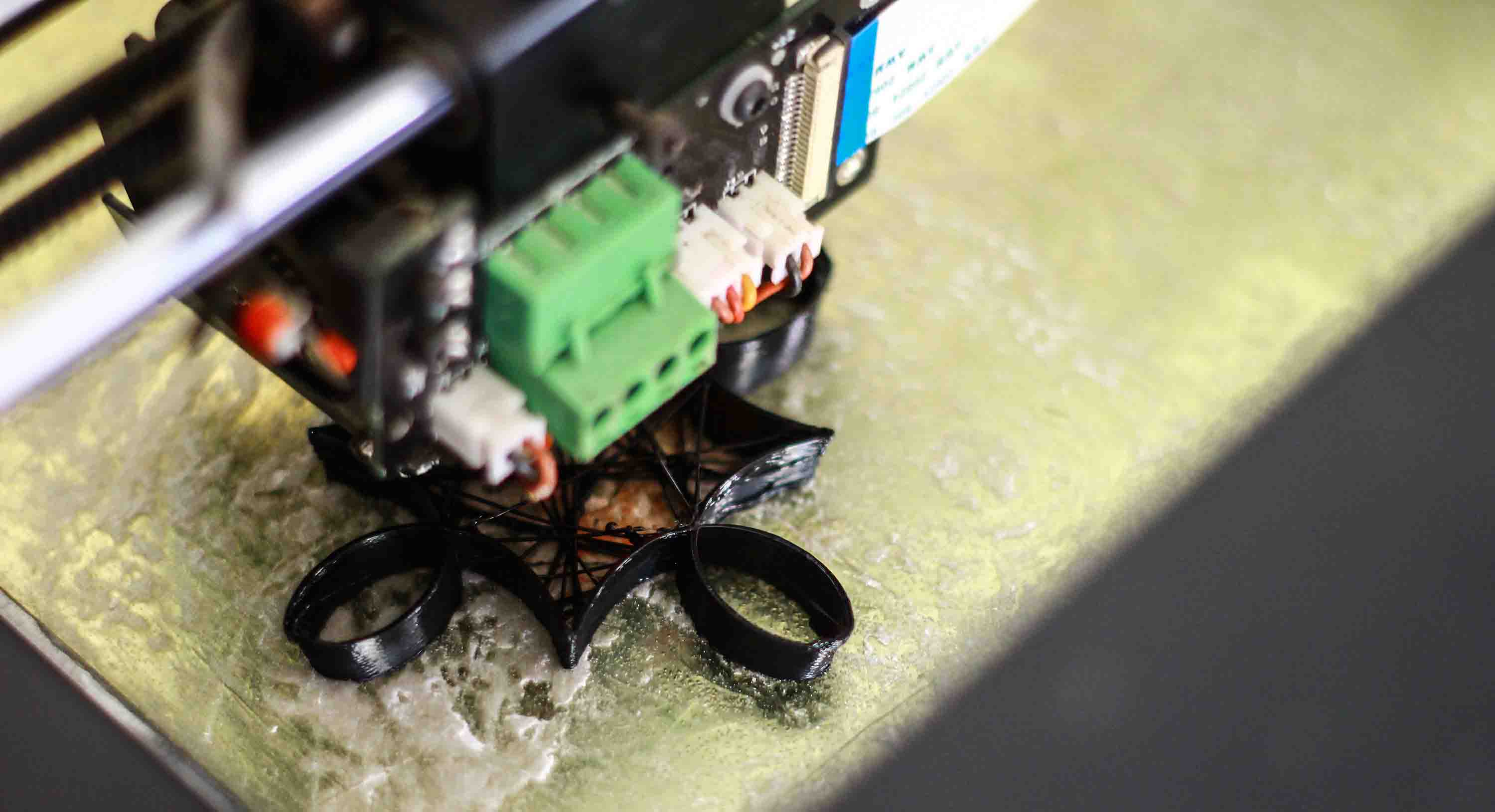
I repeated the above mentioned process to export the file to .stl format and generated the gcode with "Ultra" settings and providing the much needed supports. The 3D print came out to be pretty dishearting with only horizontal strips getting printed. I couldn't debug the process as to why the 3D printer failed to print the complete object.
Download the file here
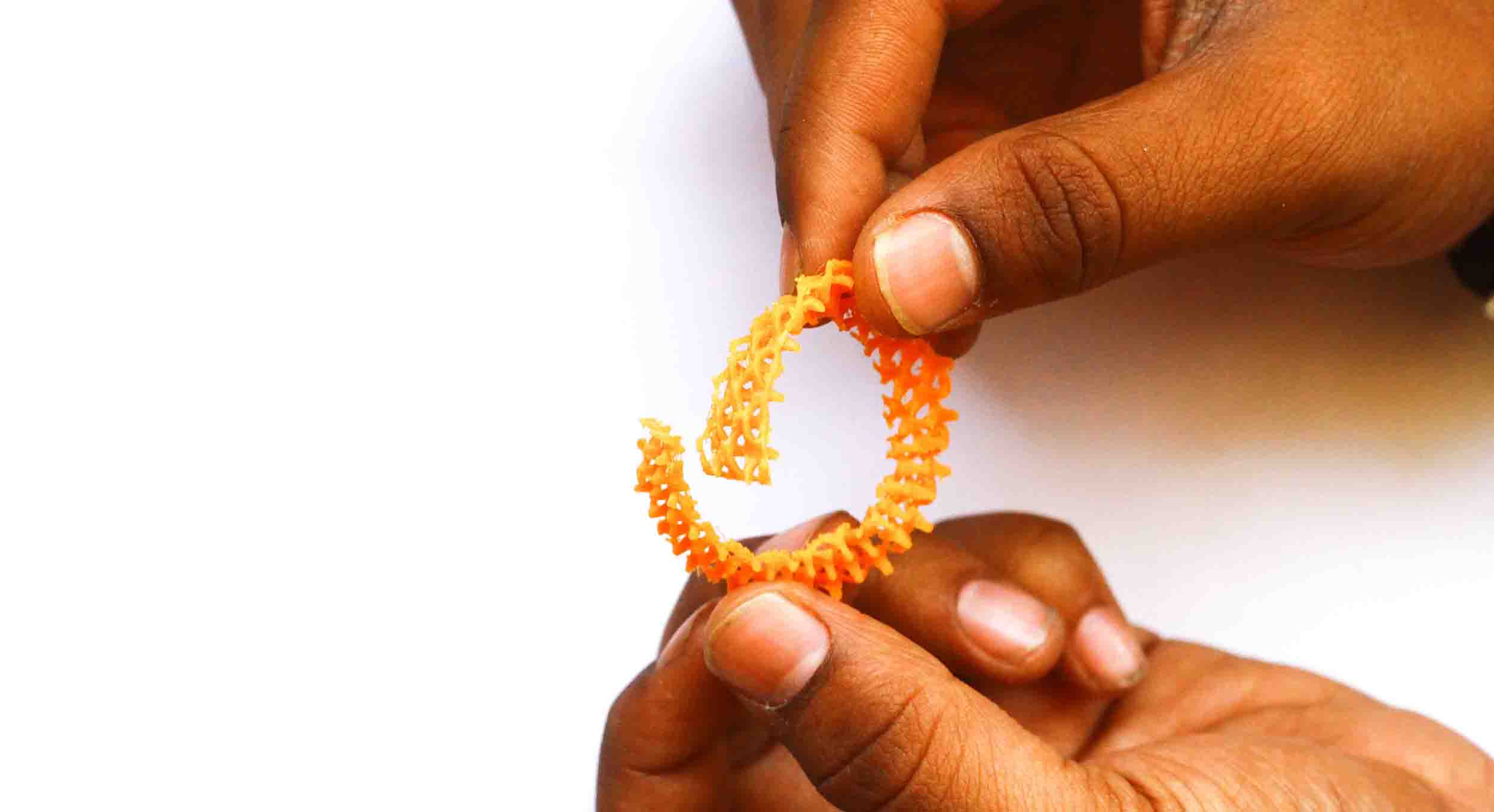
Experimentation with Gcode
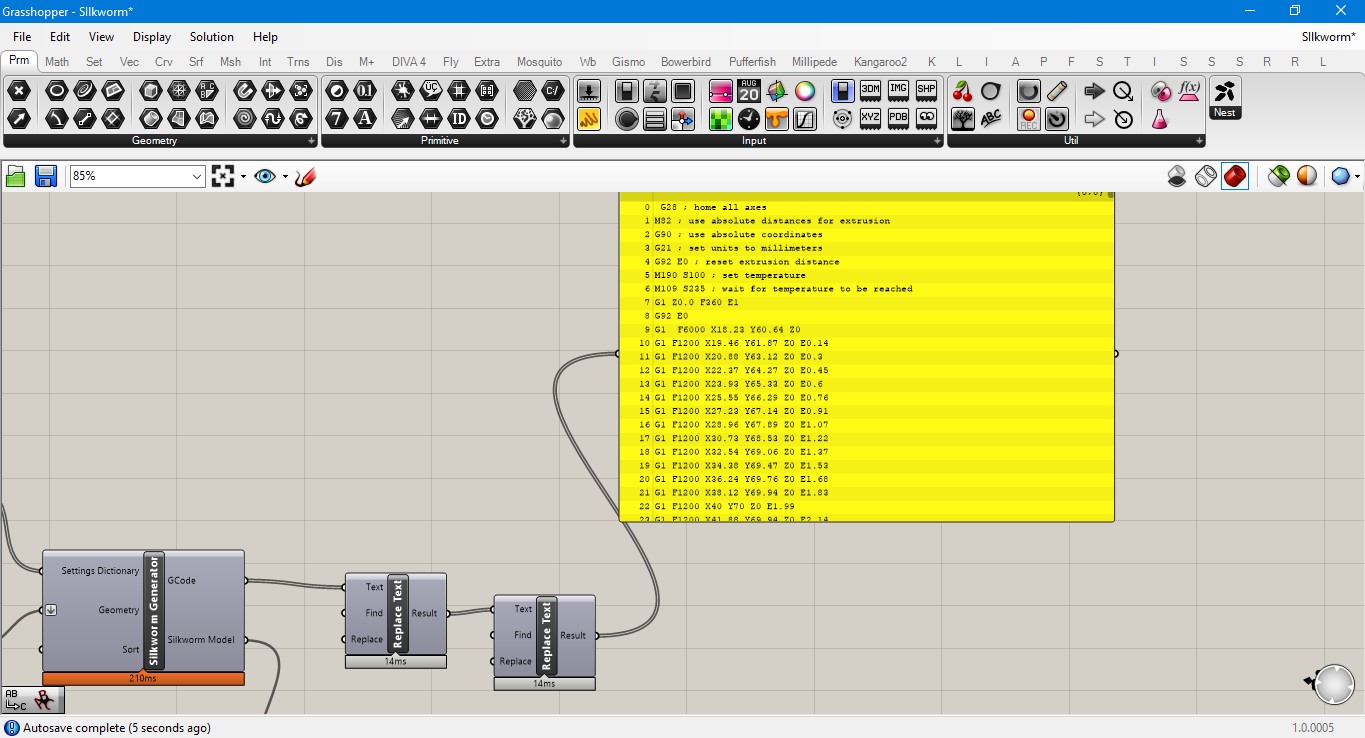
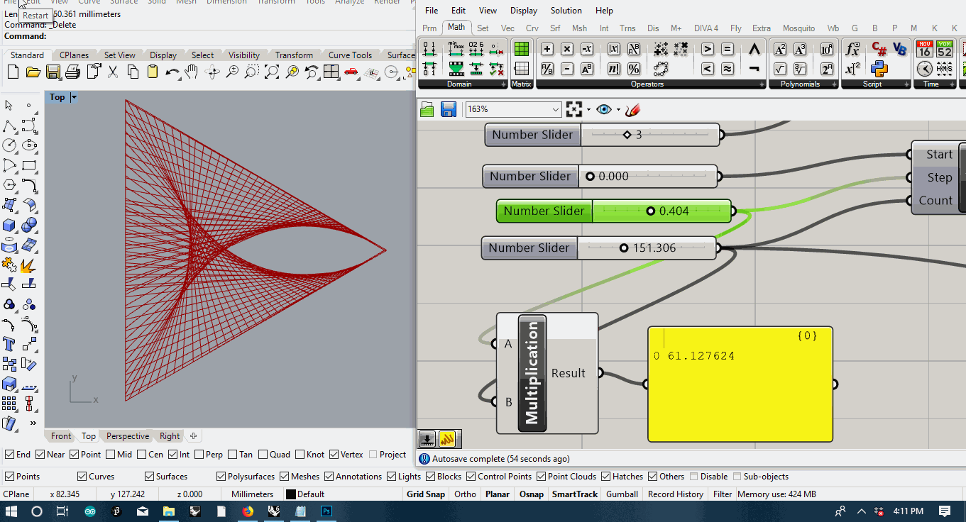
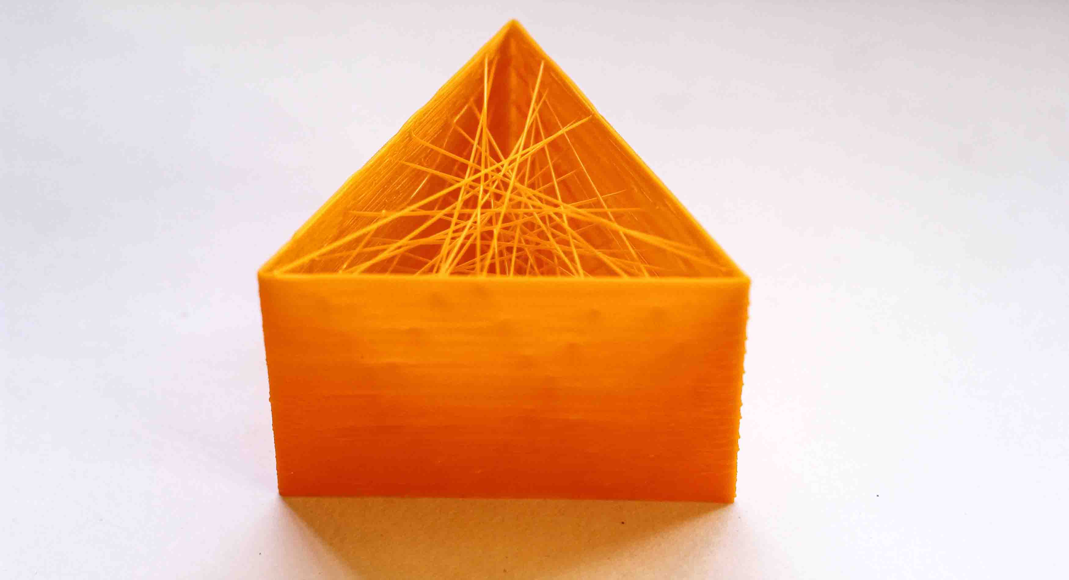
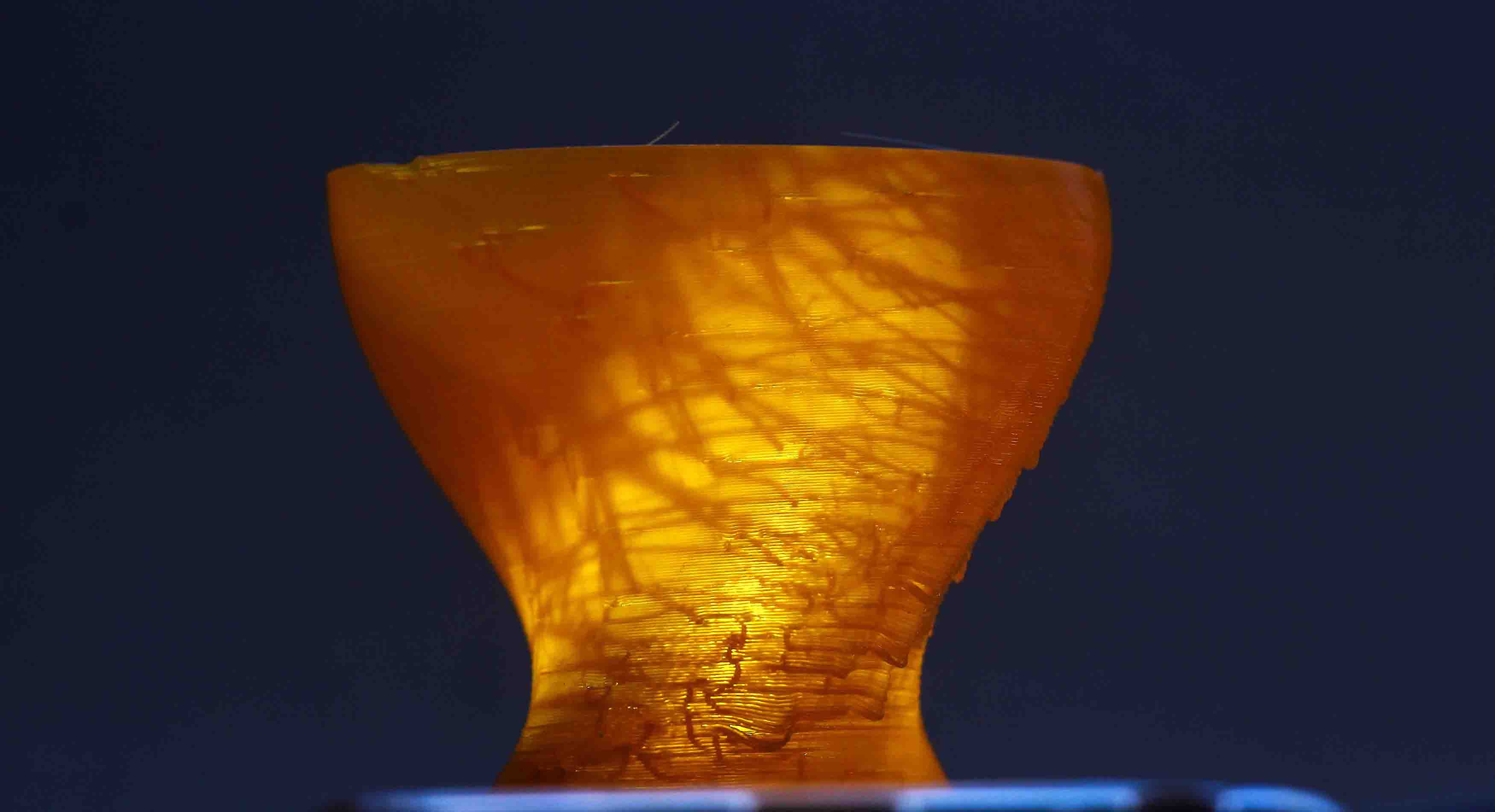
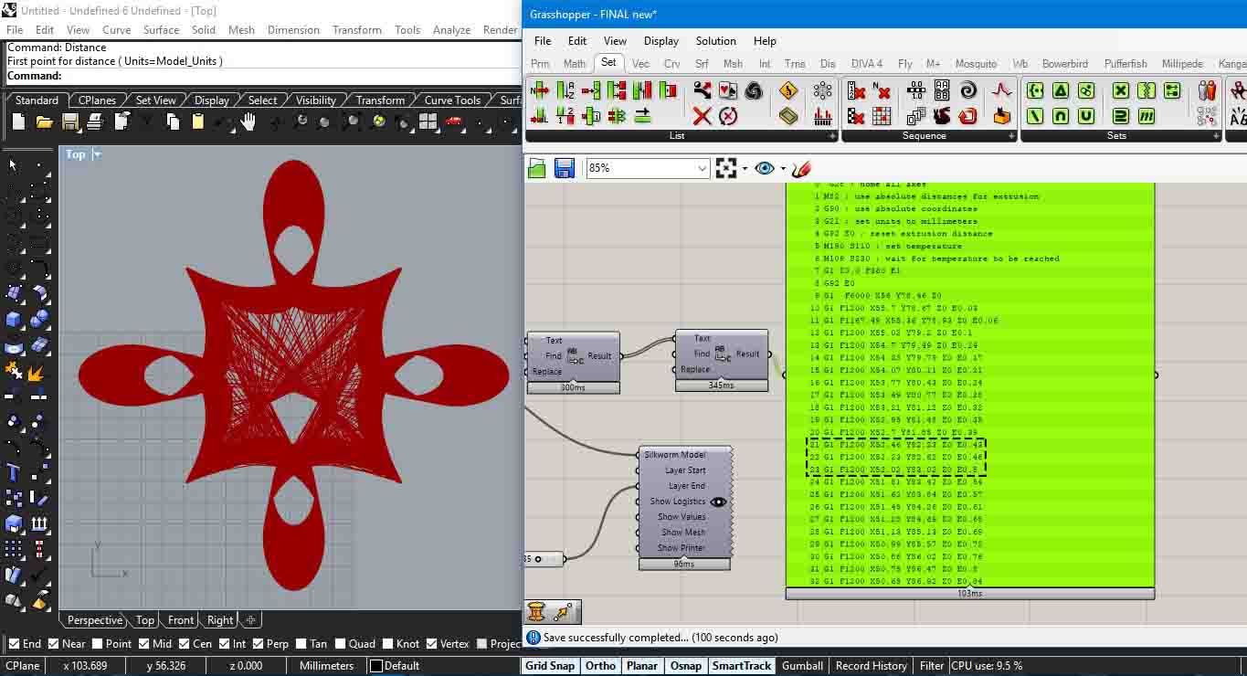
There were two things that I noticed after the above two prints, firstly, the supports in 3D printing is taking awfully lot of time and secondly its important to see how Gcode is working. With my past experience with Gcode while building my 3D printer, I went ahead to customize the Gcode in Grasshopper and see how the results came. The control over Gcode helps in providing very unexpected results. Grasshopper has a plugin called Silkworm that allows you to generate and customize the Gcode. I used an example file as a base and customized it according to my needs. The whole process to generate a Gcode is based on subdividing a curve in Grasshopper into many points, getting their coordinates and adding Gcodes to create a series of strings. The whole process involves branching and data trees.
I started with a base example file and changed things like bed temperature(using Gcode M190 S100) and extruder temperature(using Gcode M109 S235), S here depicts the temperature in celsius. In this 3D print, to be on a safer side a constant feedrate of 1200 mm/min was given denoted by F1200 in the Gcode. I further had to change the orientation of the curve because of the discrepencies in the code. One thing of importance here is that, this printing was finished under one hour and no supports were used. I would also want to stress here that an example file helped me understand what all is missing in the Grasshopper code and how well it prints with the 3D Printer available to us.
Download the file here
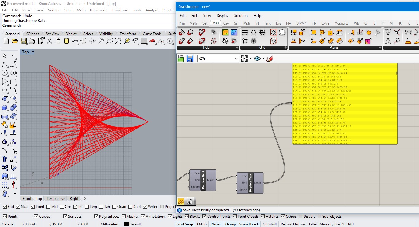
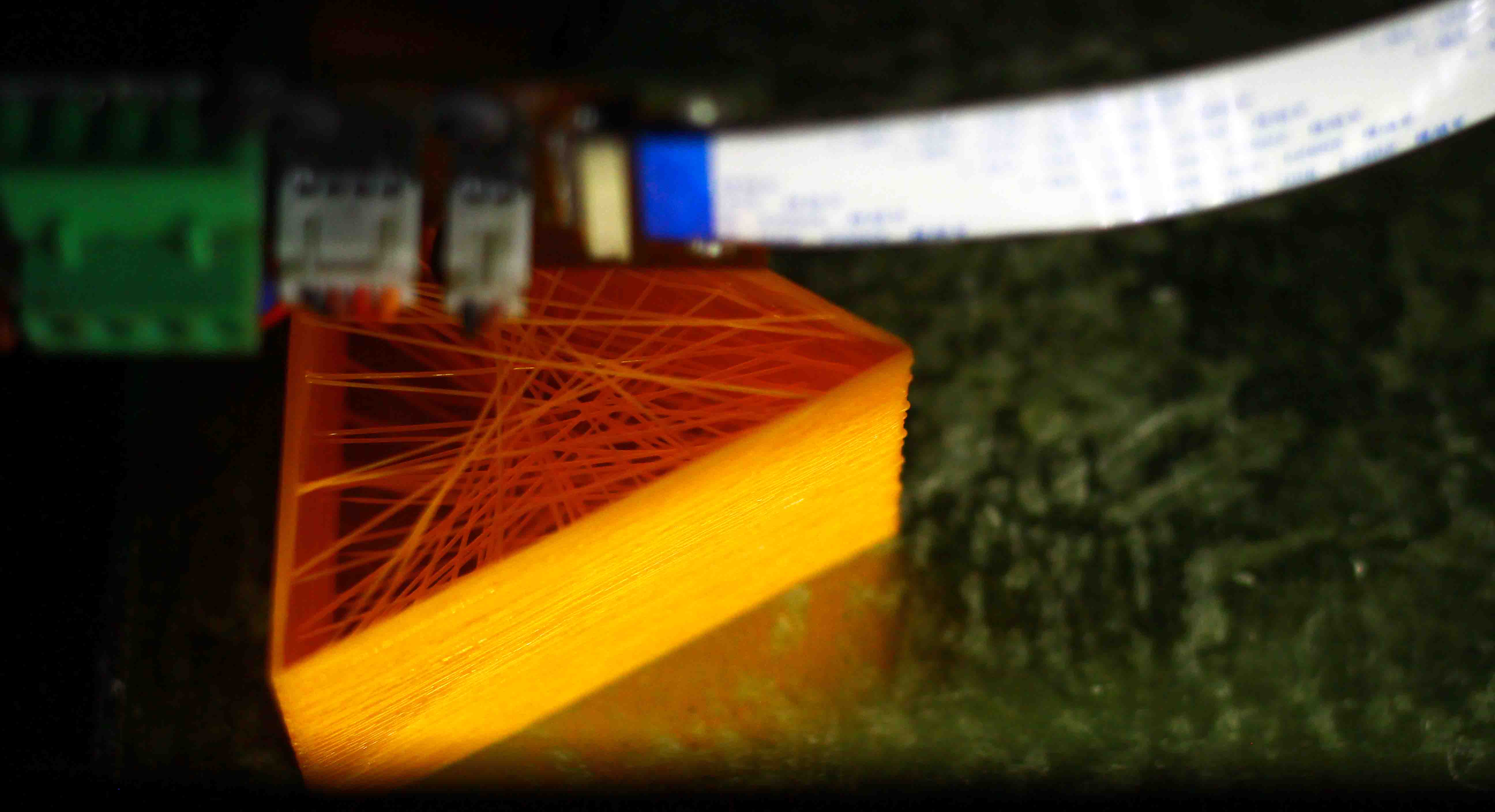
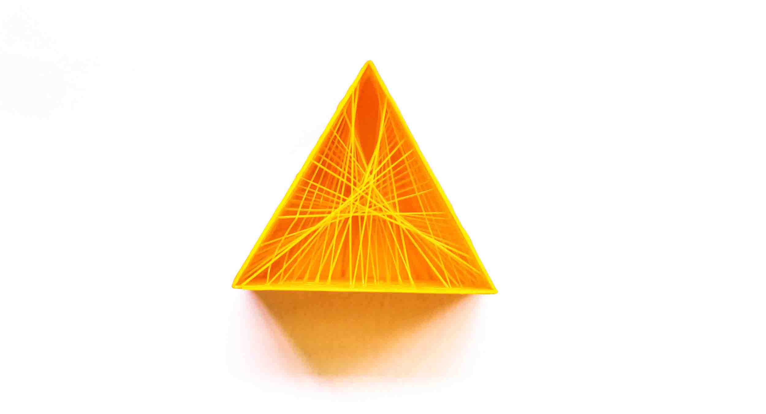
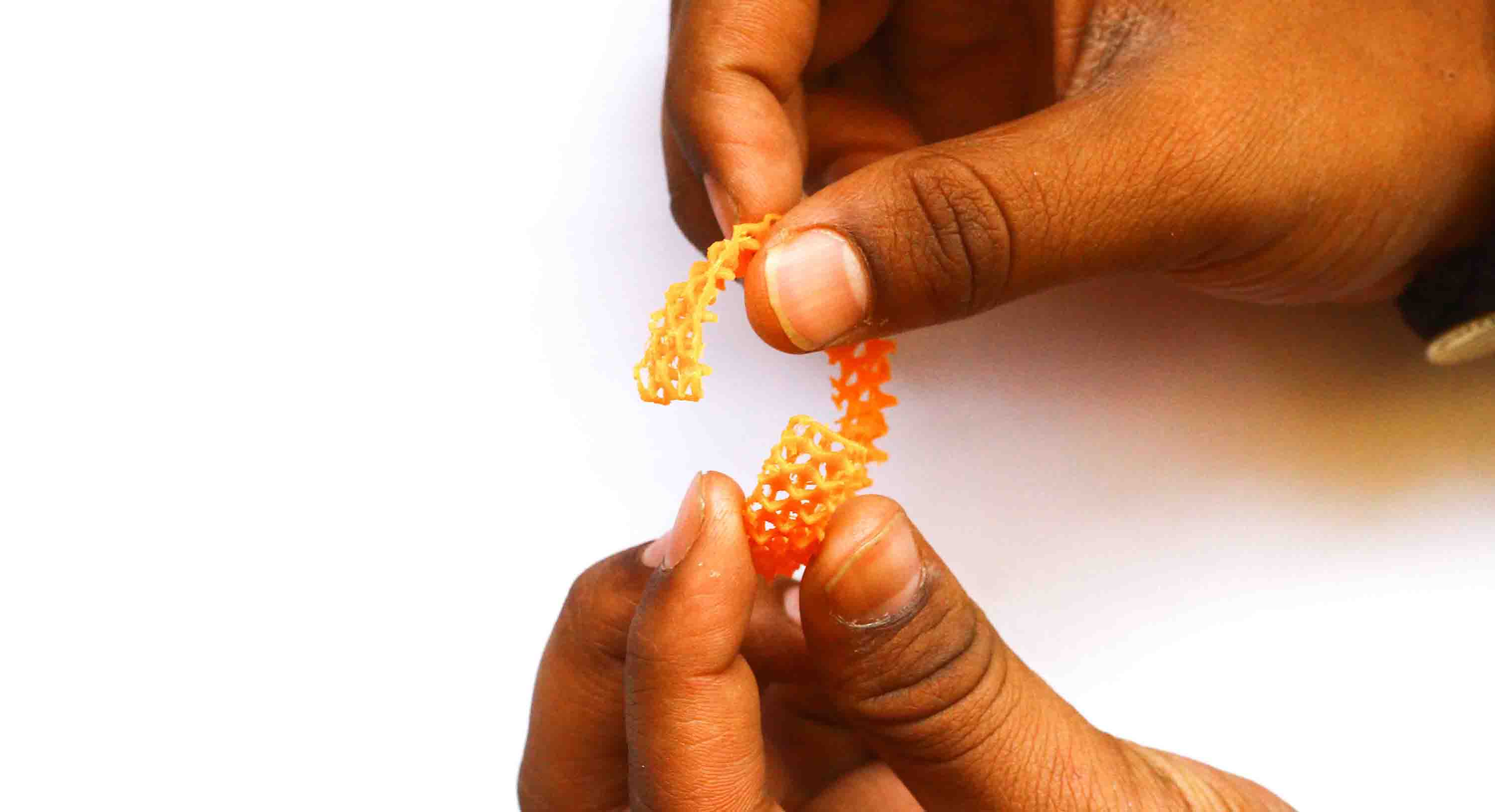
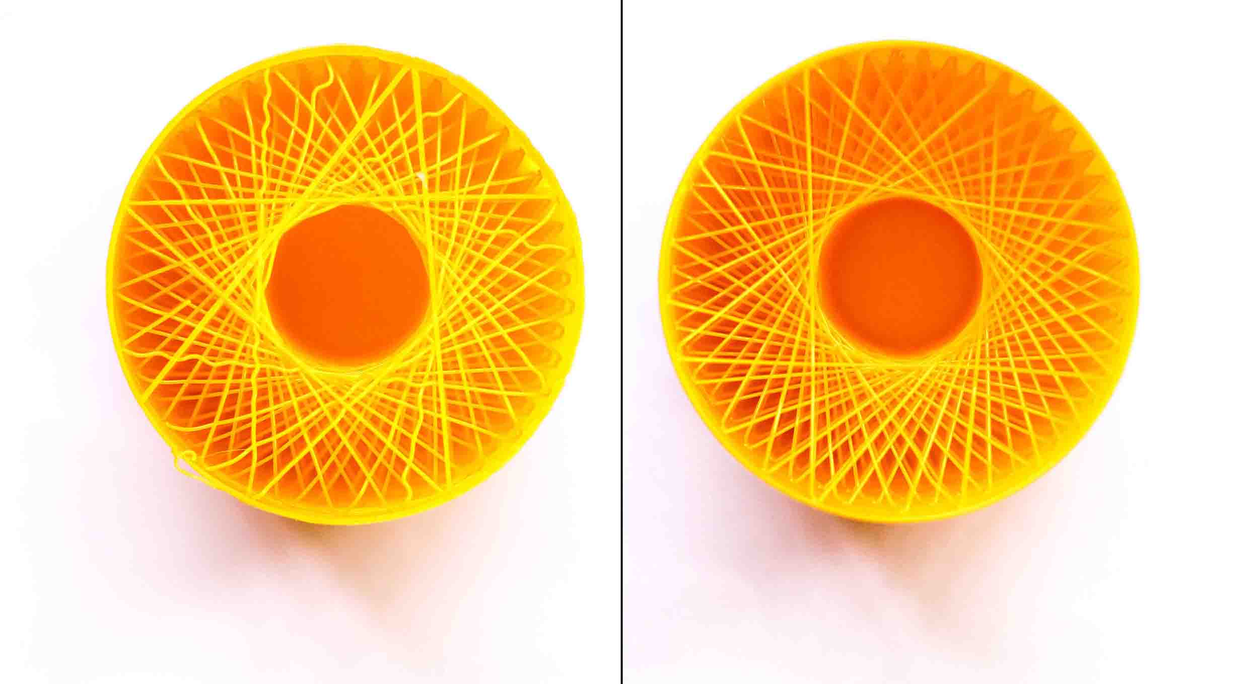
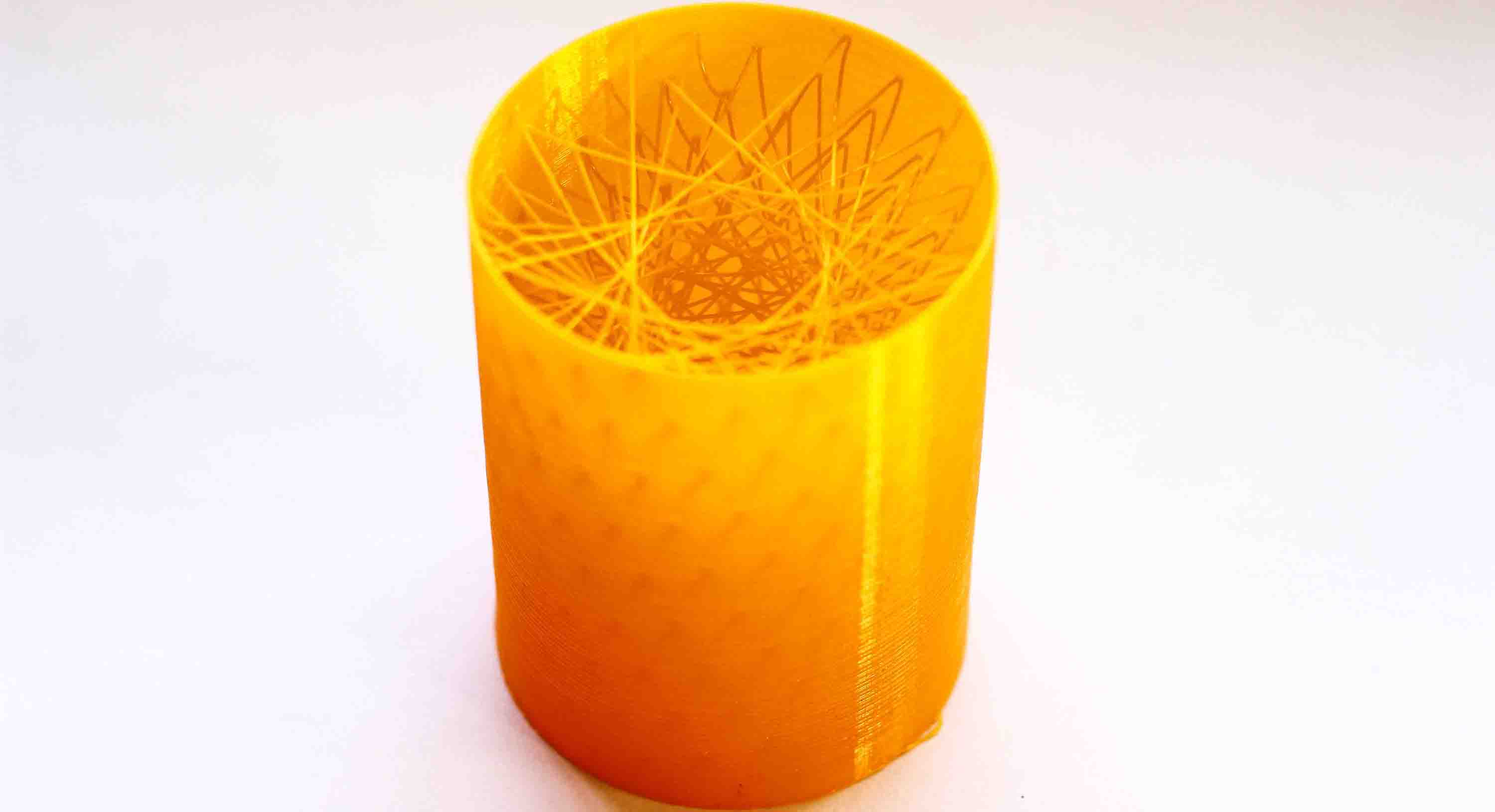
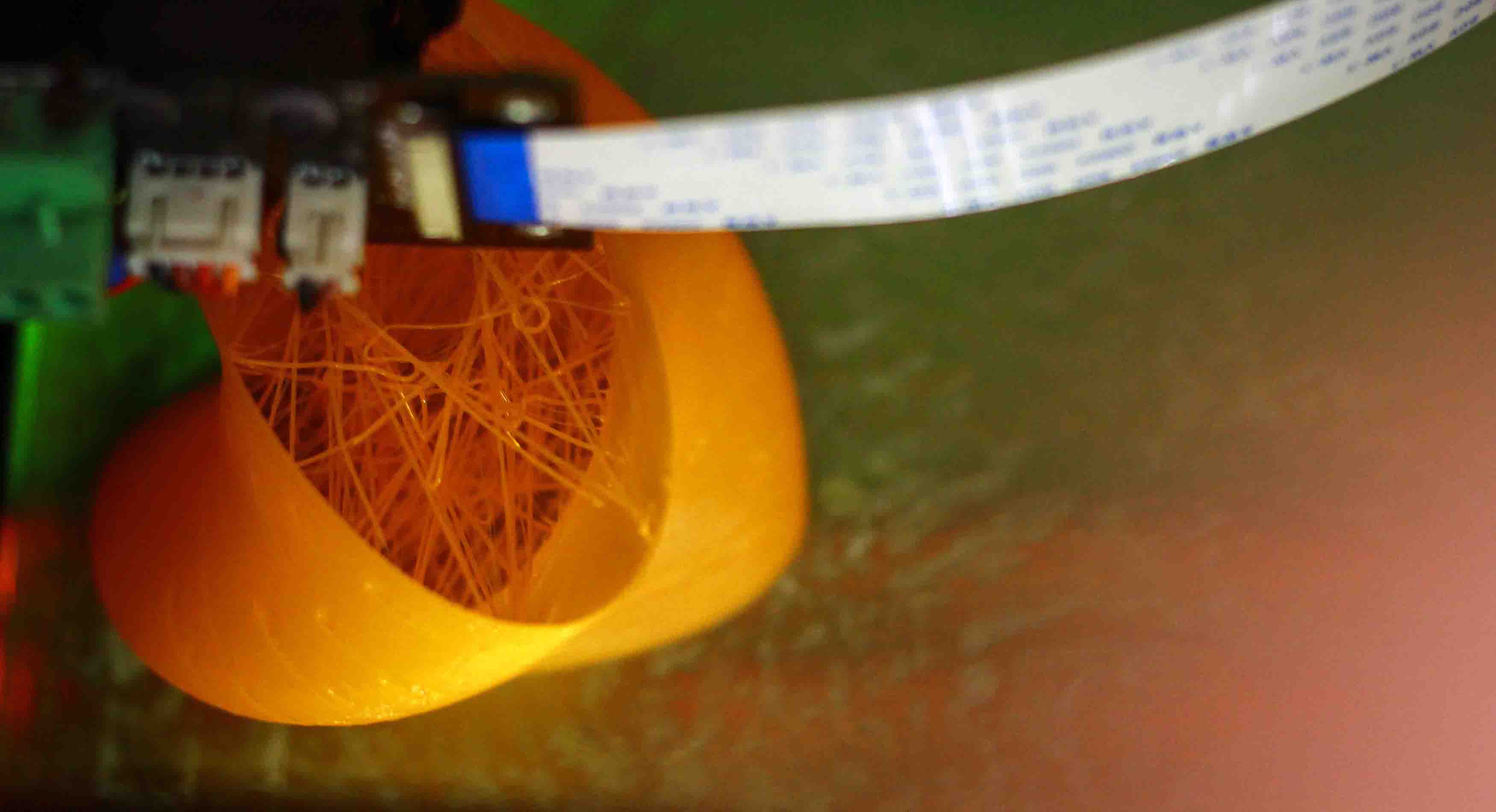
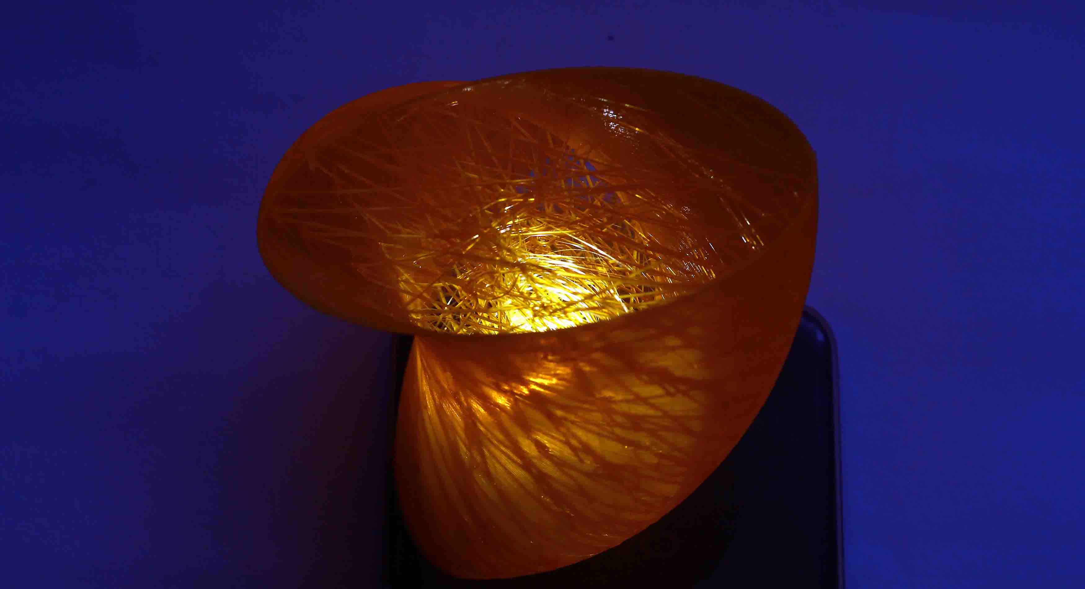
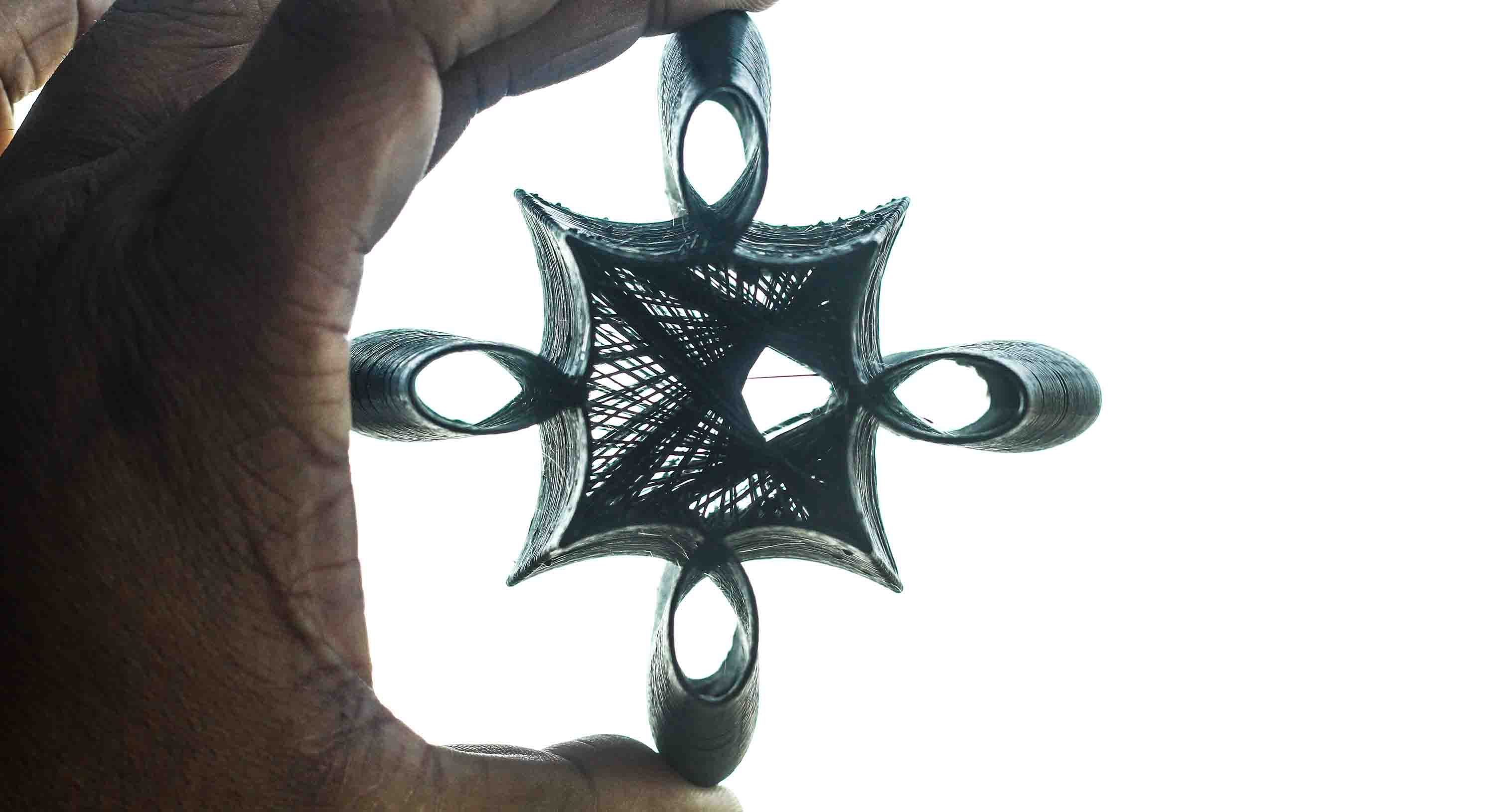
After printing the previous 3D object using custom Gcode, I next moved on to fully customizing the Gcode using Grasshopper. I also realized that I can further increase the speed of the process i.e. the feedrate. I observed in my last print that the internal structure was very lose due to slow feed rate(speed), hence in this Gcode I changed the Feedrate for both external as well as internal structure to F3000 i.e. 3000 mm/min. After printing I realized that even though the printing was very fast, the external surface is not as smooth as the previous 3D print but the internal mesh is taut, due to less time given to it to harden.
Download the file here
.jpg)
.jpg)
.jpg)
2.jpg)
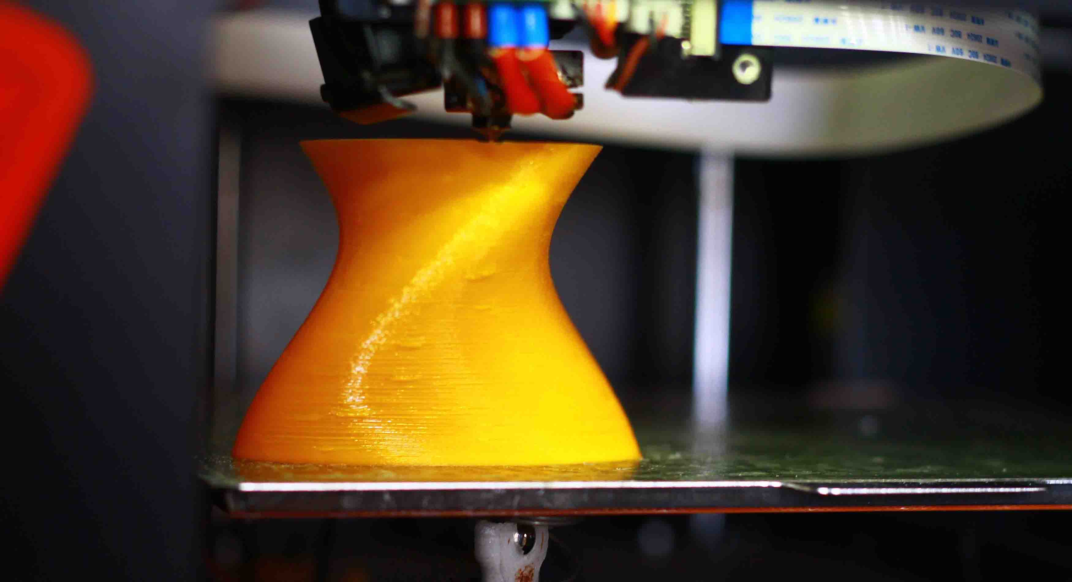
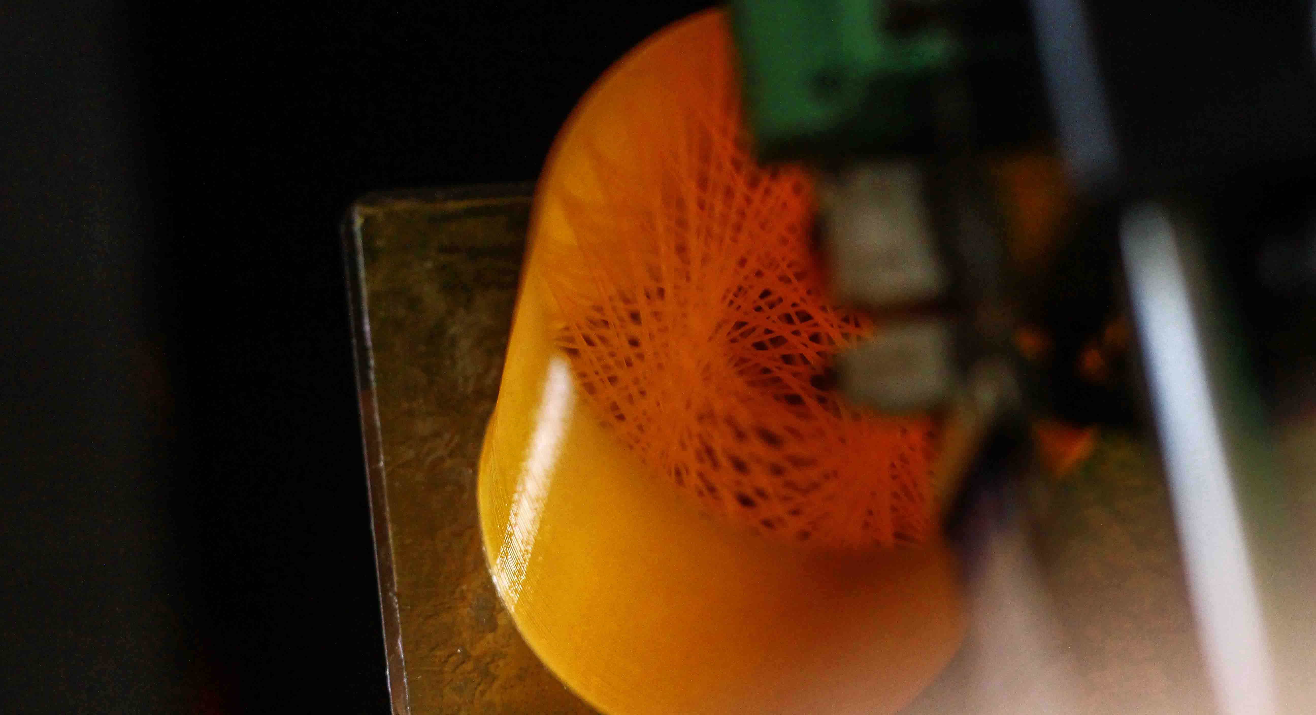
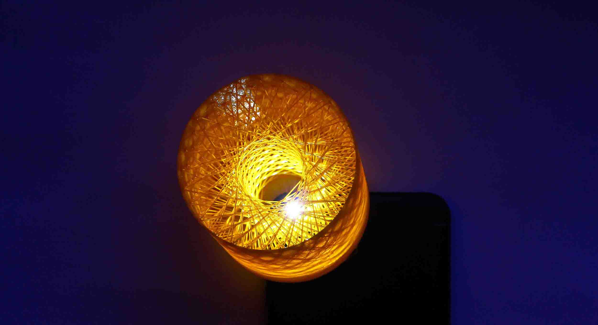
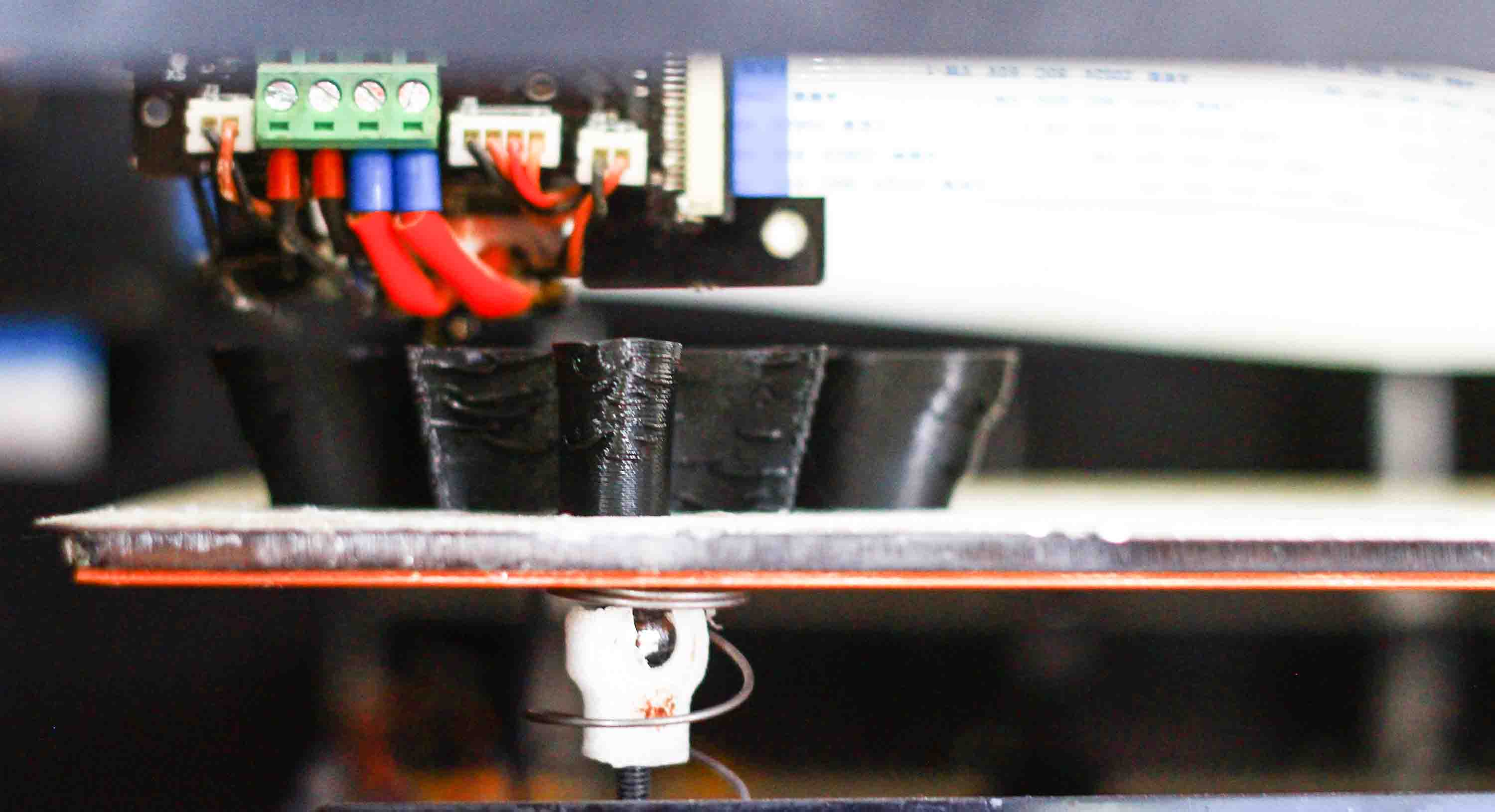
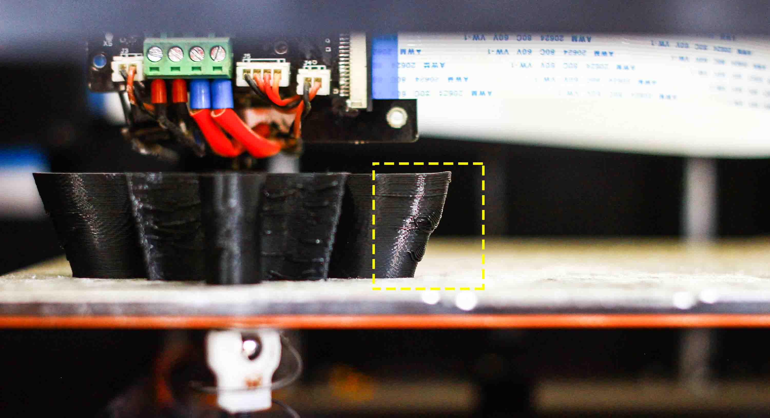
I further moved to challenge myself as to how the printer will behave if I create a curved geometry(overhanging in ths case). I twisted the ellipse and generated a Gcode changing the value of external surface feedrate(speed) to F1200(Gcode) and internal feedrate to F6000. The result was a failure since F6000 was way too much for the internal mesh. Also, the feedrate of F1200 turned out to be a bit too much for the external overhang. Hence, in the next iteration, I reduced the twisting. hence the overhang and brought down the internal mesh feedrate to F3000. The result was better now but still there was a lot of room for improvement.
Download the file here
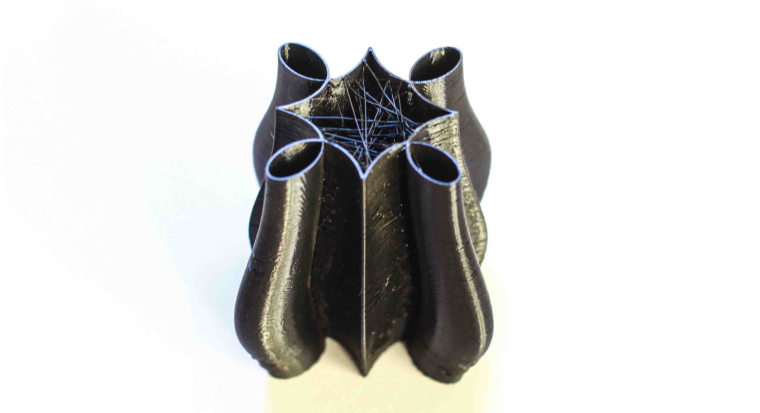
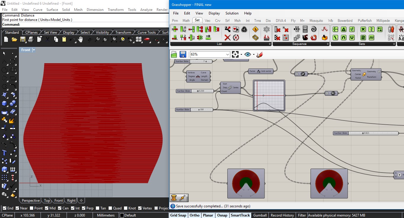
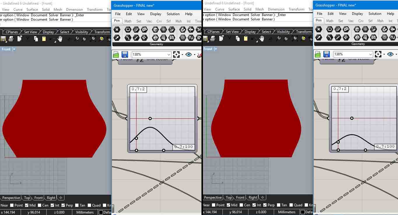
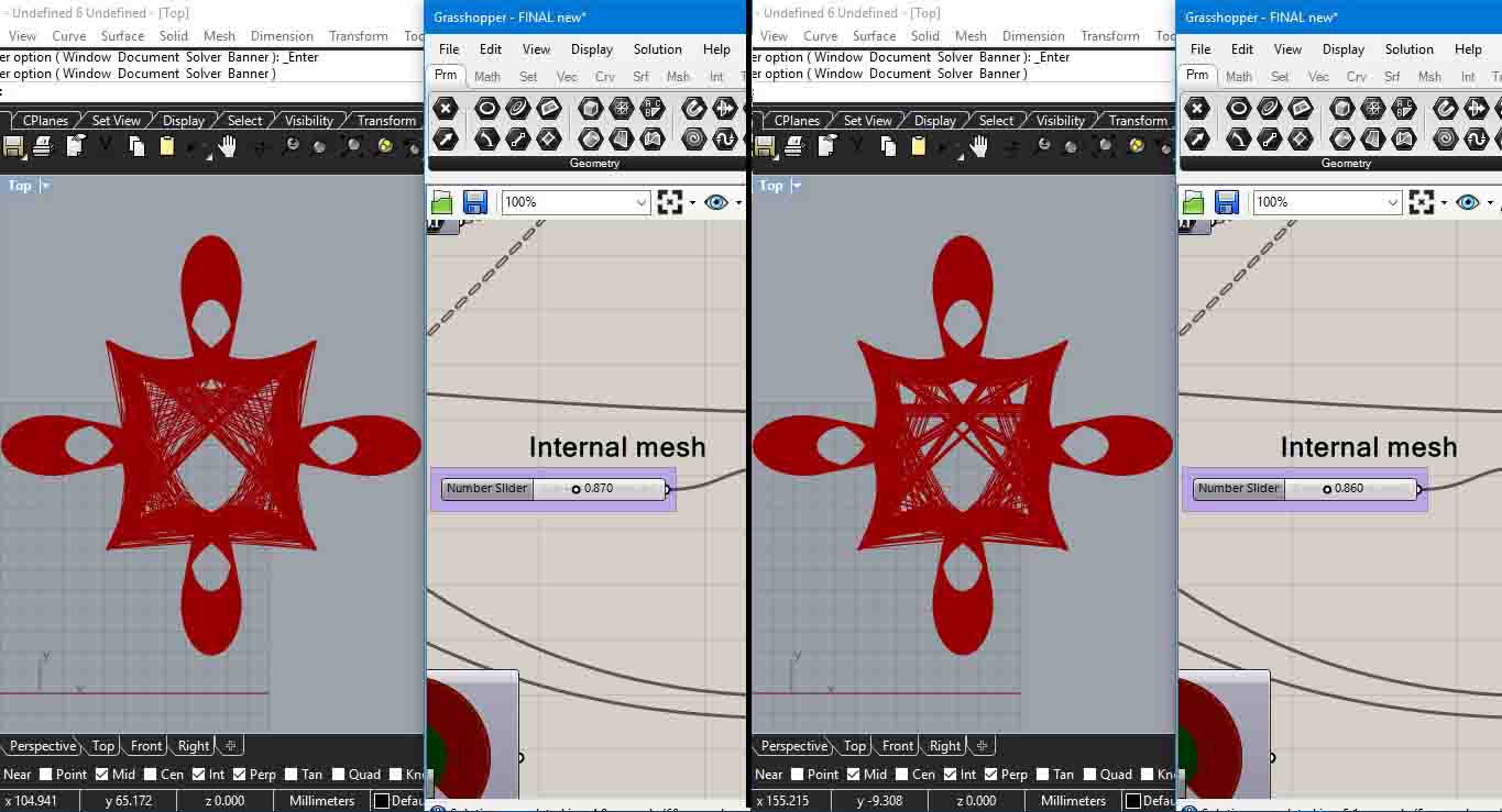
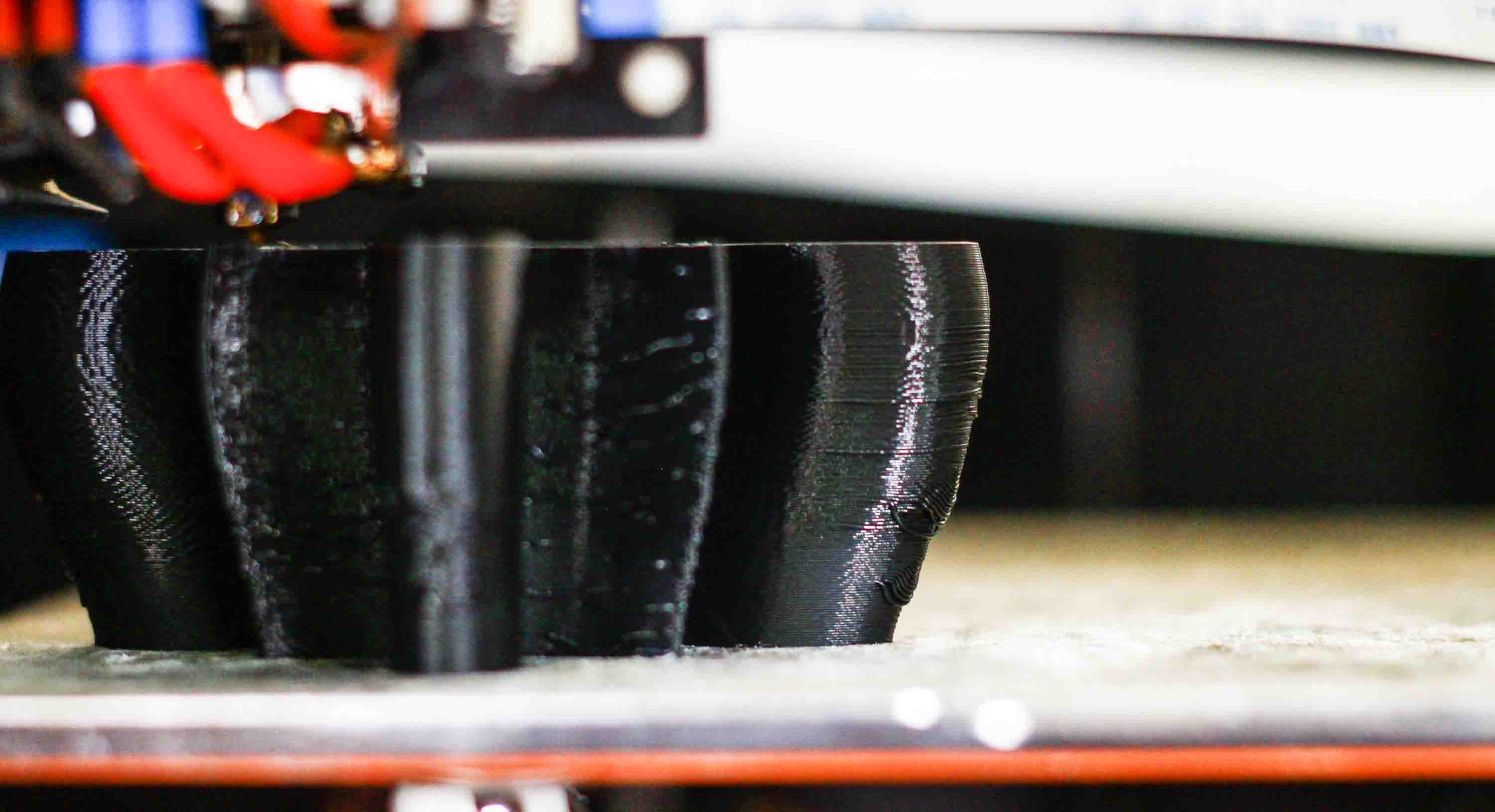
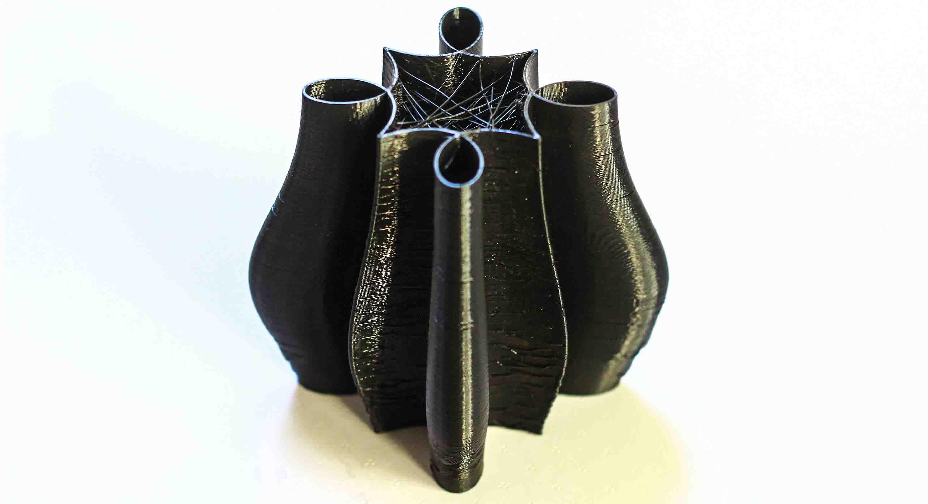
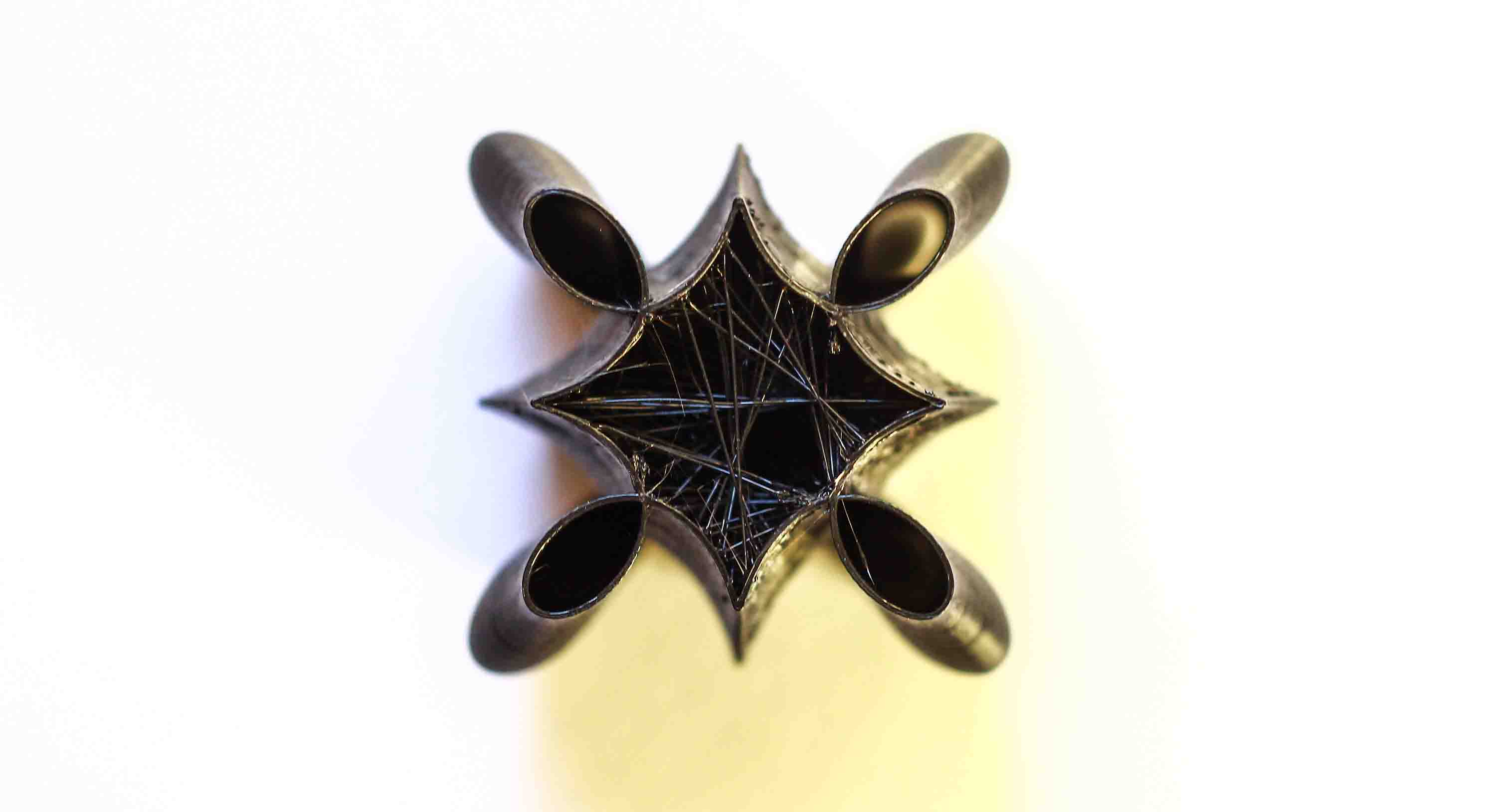
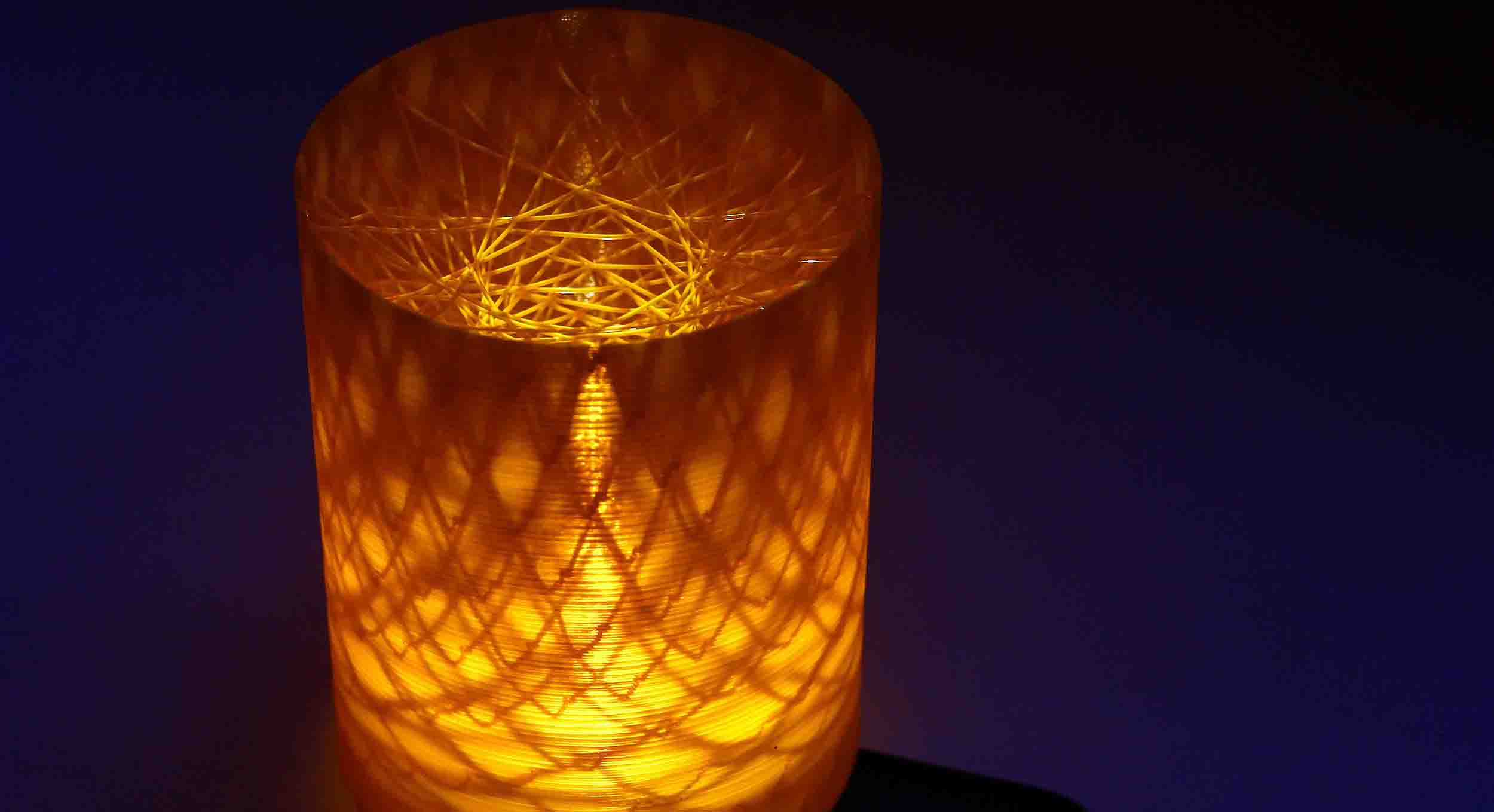
Most of the geometries that I made above didn't include any kind of crossovers, they were mostly closed curves without any kinks. In the grasshopper code, I added Gaussian normal distribution curve for the external geometry. The geometry I made could be further thought of as 4 geometries surrounding the one geometry but all connected. Furthermore, I also didn't try making anything with ABS(Acrylonitrile butadiene styrene). ABS is tougher than PLA and I wanted to see how the surface finish comes up. To be on a safer side, I kept the feedrate at F1200. One of the parameters, I included is the internal mesh density. By changing the number slider marked "Internal Mesh" one can change pattern of internal mesh and also its density.
Download the file here