Workflow of Assignment:
Group Assignment:
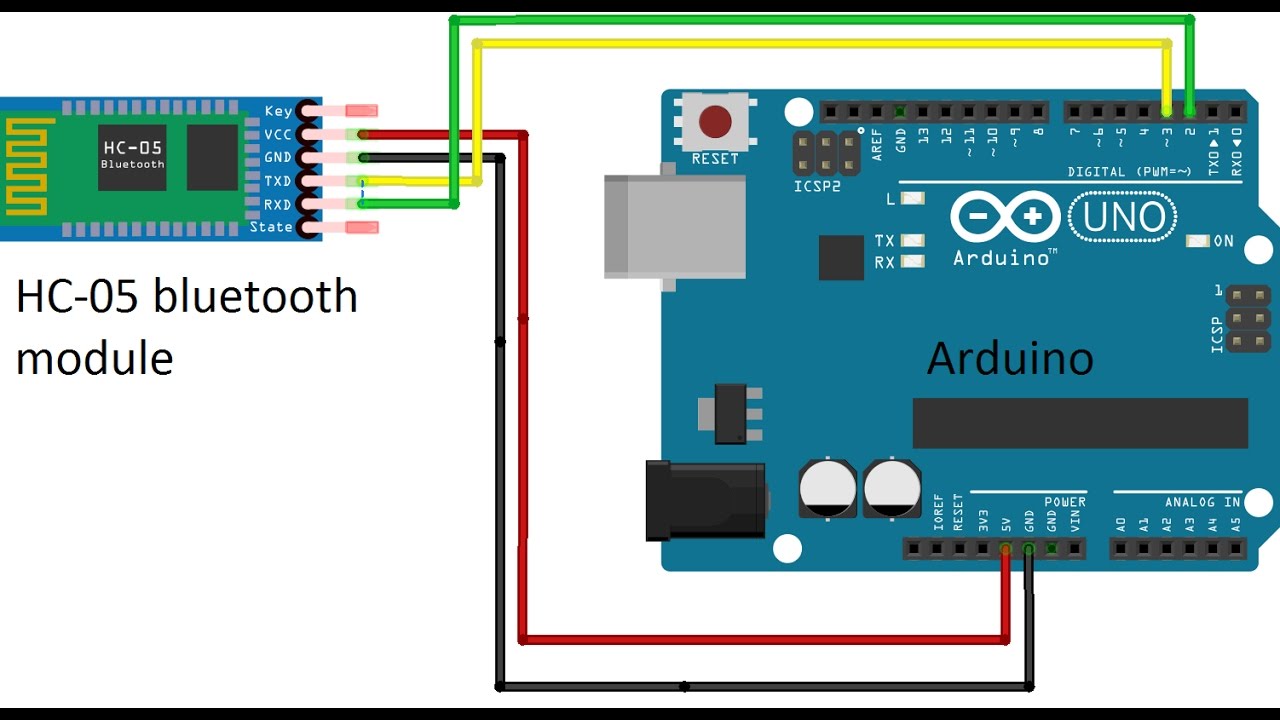
Tushar and me teamed up to use bluetooth HC-05 with arduino to send message which is displayed on Serial Monitor. I followed the tutorial by Mechatronics.
HC-05 module is an easy to use Bluetooth SPP (Serial Port Protocol) module, designed for transparent wireless serial connection setup. Serial port Bluetooth module is fully qualified Bluetooth V2.0+EDR (Enhanced Data Rate) 3Mbps Modulation with complete 2.4GHz radio transceiver and
B. Code:
Pin 2 and 3 will Recieve(RX) and trasmit(TX) communication data. 9600 is the baud rate for software serial communication. Serial.write() will print character received on the serial monitor.
#include SoftwareSerial.h>

/* Create object named bt of the class SoftwareSerial */
SoftwareSerial bt(2,3); /* (Rx,Tx) */

void setup() {
  bt.begin(9600); /* Define baud rate for software serial communication */
  Serial.begin(9600); /* Define baud rate for serial communication */
}

void loop() {

    if (bt.available()) /* If data is available on serial port */
    {
     Serial.write(bt.read()); /* Print character received on to the serial monitor */
    }
}
C.Application:
There are many application in the Play Store for this purpose which will work with the Arduino code that we uploaded I downloaded BLE Terminal and paired the mobile by default password of HC-05 module 1234.It worked successfully where the words written on mobile were reflected on serial monitor.
Individual Assignment:
Networking And Communication:
Data communication refers to the transmission of the digital data between two or more uC. The physical connection between networked computing devices is established using either cable media or wireless media. The best-known communication network is the Internet.
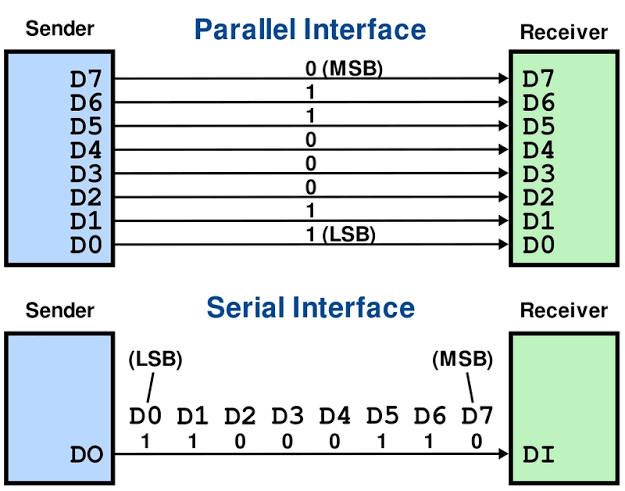
1.Parallel Communication:
Parallel interfaces transfer multiple bits at the same time. They usually require buses of data - transmitting across eight, sixteen, or more wires. Data is transferred in huge, crashing waves of 1’s and 0’s.It transmit multiple bits of data at same time.they require buses of data to transmitting across eight, sixteen, or more wires.
2. Serial Communication:
Serial interfaces stream their data, one single bit at a time. These interfaces can operate on as little as one wire, usually never more than four. But this way of communication is slow, but its more reliable compare to Parallel.
A. Synchronous serial interface :
synchronous serial interface means this both sender and receiver shares the same clock. This makes for a more straightforward, often faster serial transfer, but it also requires at least one extra wire between communicating devices. eg,SPI, and I2C.
B. Asynchronous serial interface:
Asynchronous means that data is transferred without support from an external clock signal. This way of transmission method is perfect for minimising the required wires and I/O pins. This method established trough Rx and TX pins in MCUs.Device like GSM, GPS, Xbee etc. are connected using this mode.
I'm going to use I2C communication protcol interfacing in this week. I2C Protocol is described as below:
I2C is a serial protocol for two-wire interface to connect low-speed devices like microcontrollers, EEPROMs, A/D and D/A converters, I/O interfaces and other similar peripherals in embedded systems. It was invented by Philips and now it is used by almost all major IC manufacturers. Each I2C slave device needs an address.
I2C bus is popular because it is simple to use, there can be more than one master, only upper bus speed is defined and only two wires with pull-up resistors are needed to connect almost unlimited number of I2C devices. I2C can use even slower microcontrollers with general-purpose I/O pins since they only need to generate correct Start and Stop conditions in addition to functions for reading and writing a byte.
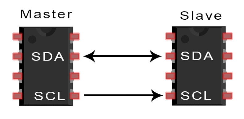
I2C Interface:
I2C uses only two wires: SCL (serial clock) and SDA (serial data). Both need to be pulled up with a resistor to +Vdd. There are also I2C level shifters which can be used to connect to two I2C buses with different voltages.
I2C Addresses:
Basic I2C communication is using transfers of 8 bits or bytes. Each I2C slave device has a 7-bit address that needs to be unique on the bus. Some devices have fixed I2C address while others have few address lines which determine lower bits of the I2C address. This makes it very easy to have all I2C devices on the bus with unique I2C address. There are also devices which have 10-bit address as allowed by the specification.
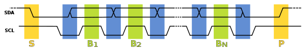
In normal state both lines (SCL and SDA) are high. The communication is initiated by the master device. It generates the Start condition (S) followed by the address of the slave device (B1). If the bit 0 of the address byte was set to 0 the master device will write to the slave device (B2). Otherwise, the next byte will be read from the slave device. Once all bytes are read or written (Bn) the master device generates Stop condition (P). This signals to other devices on the bus that the communication has ended and another device may use the bus.
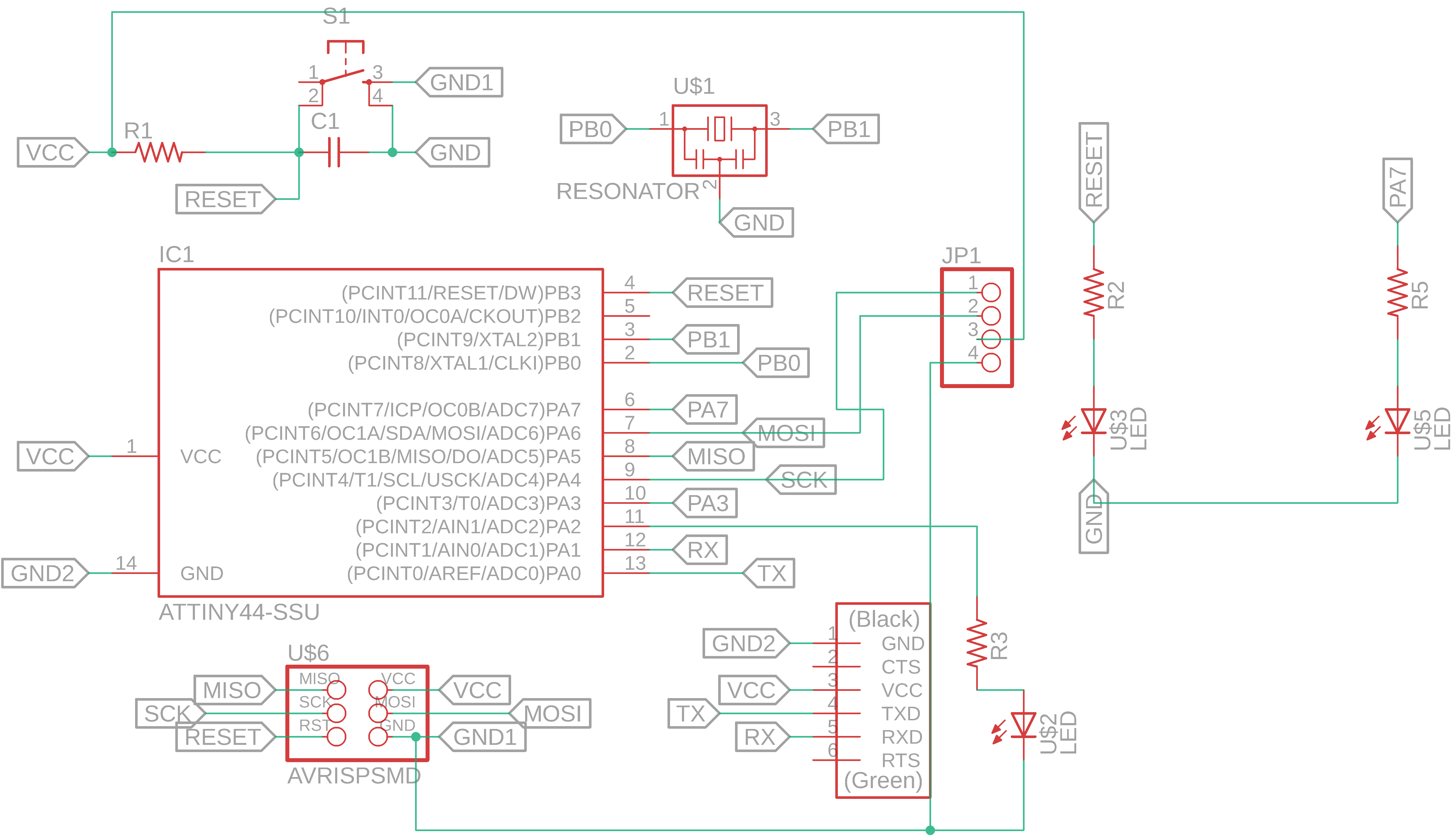
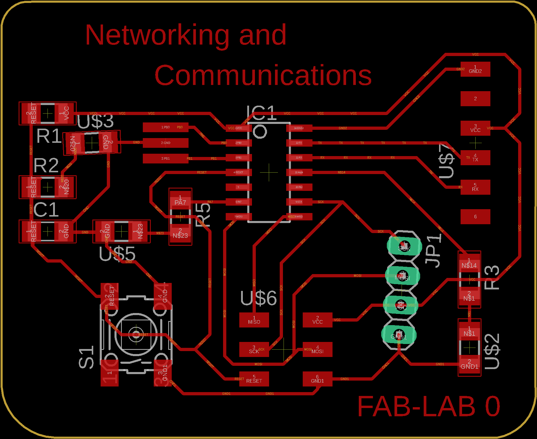
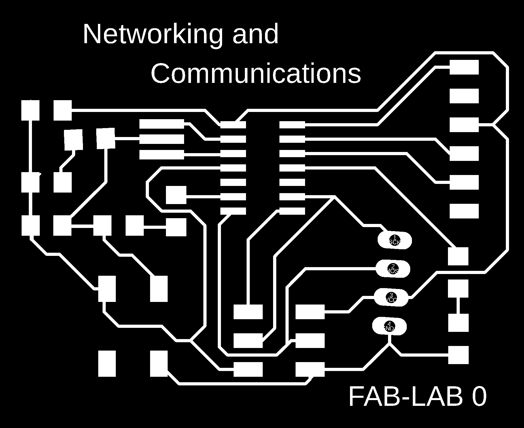
PCB Design:
Here, I'm going to design 1 Master board and 2 Slave boards PCB in EAGLE software. But there is same design for all 3 boards are as follws:
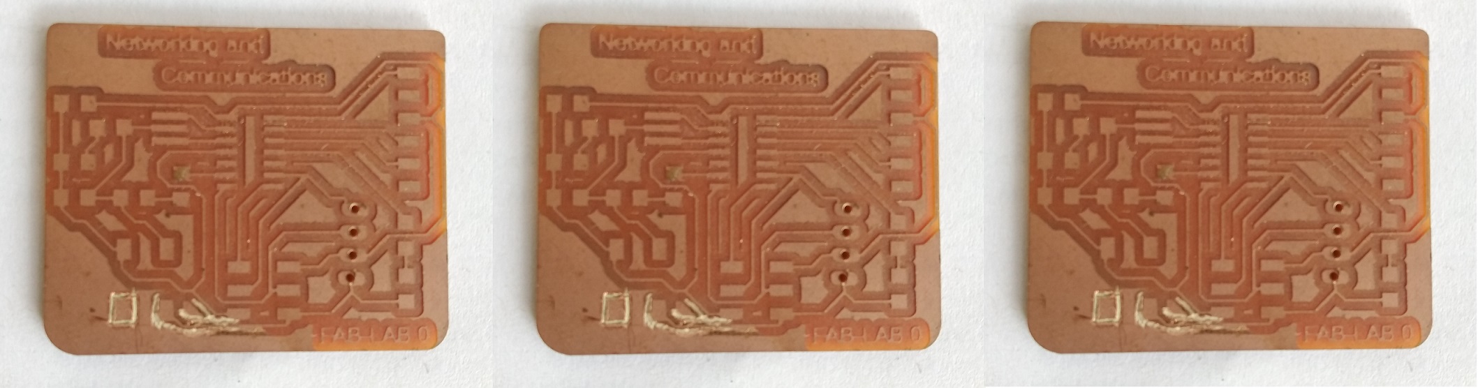
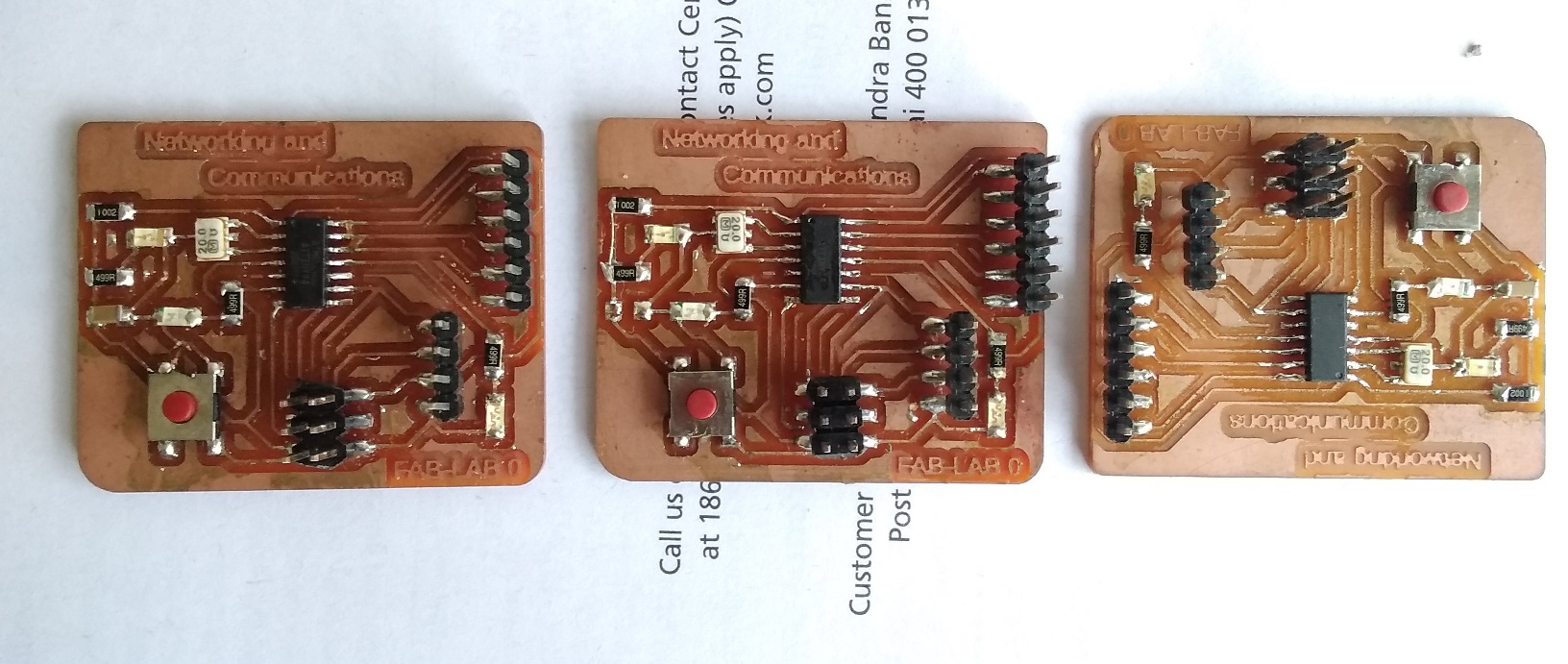
PCB Milling:
Now the design file from the EAGLE is ready. Next step is to mill the circuit board on SRM 20. Complted three boards, one is master and another two as a slave, are shown in below:
PCB Soldering:
Once the milling is done components are supposed to be soldered on the board. Soldering is being done.
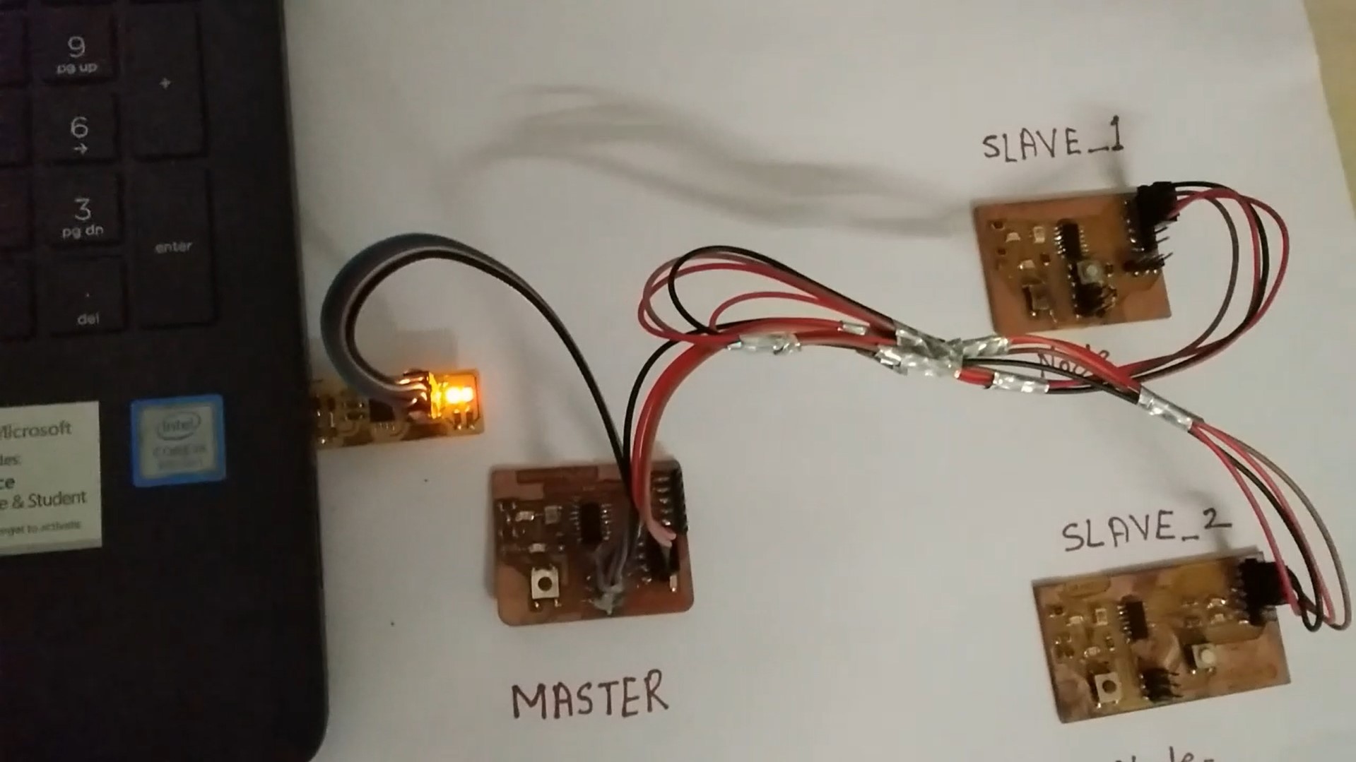
Connections:
Once all the components are soldered the board is ready to test now. For the testing I have to do connections between master and salves. Following figure is shows connections between master and slaves:
Coding:
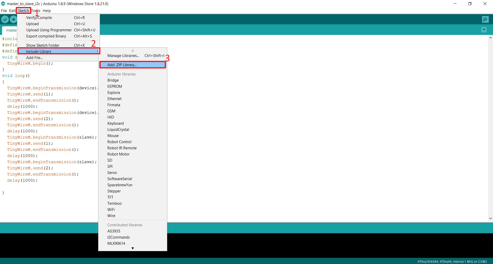
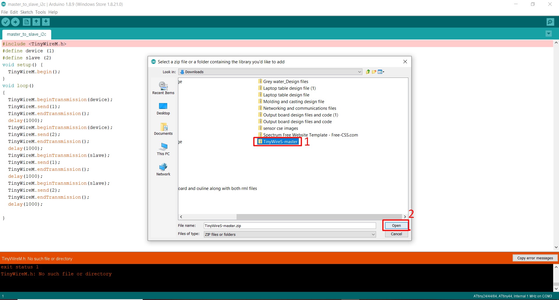
While I'm uploading code to my 'Master board' of networking, I see following error:
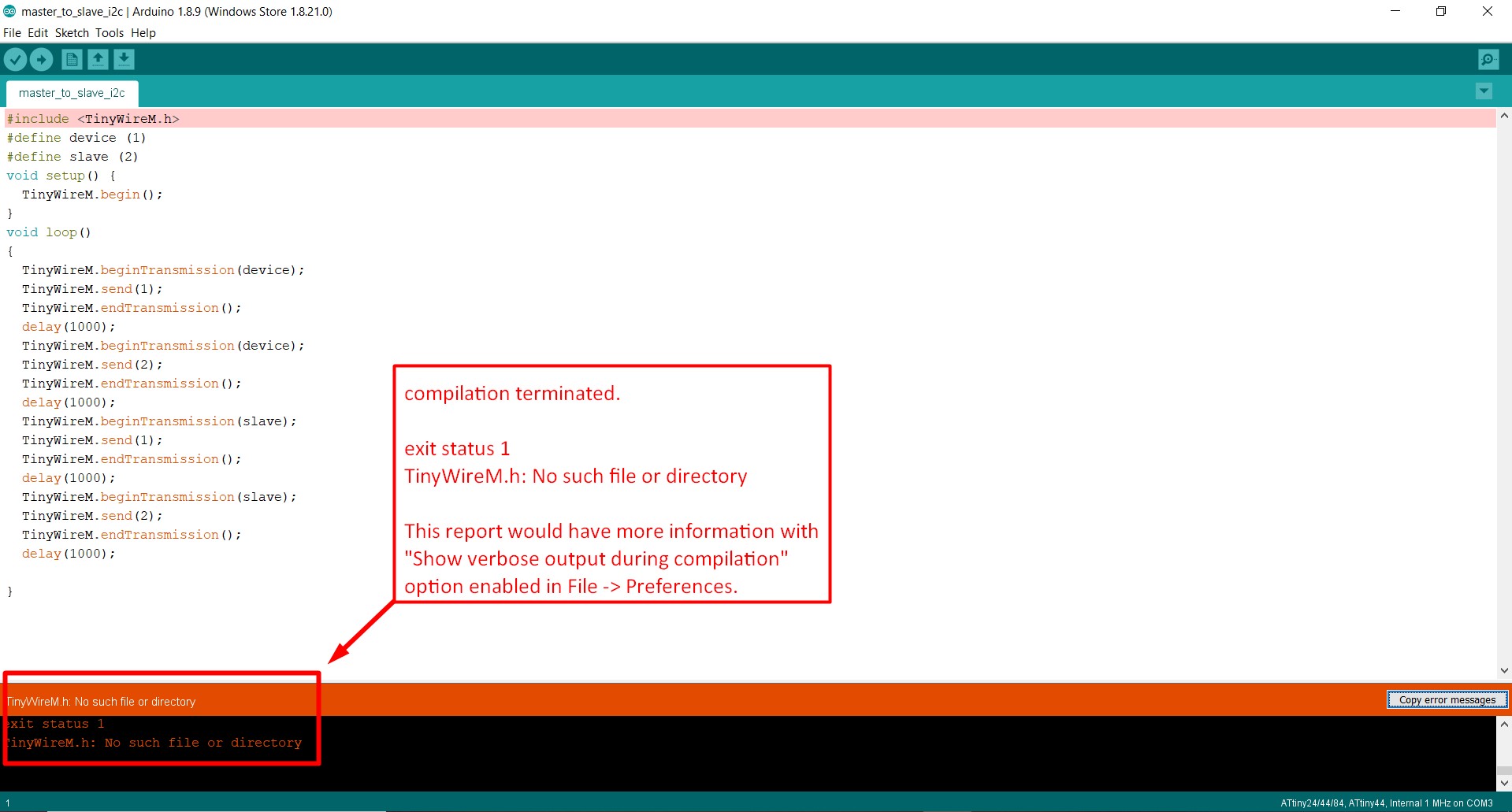
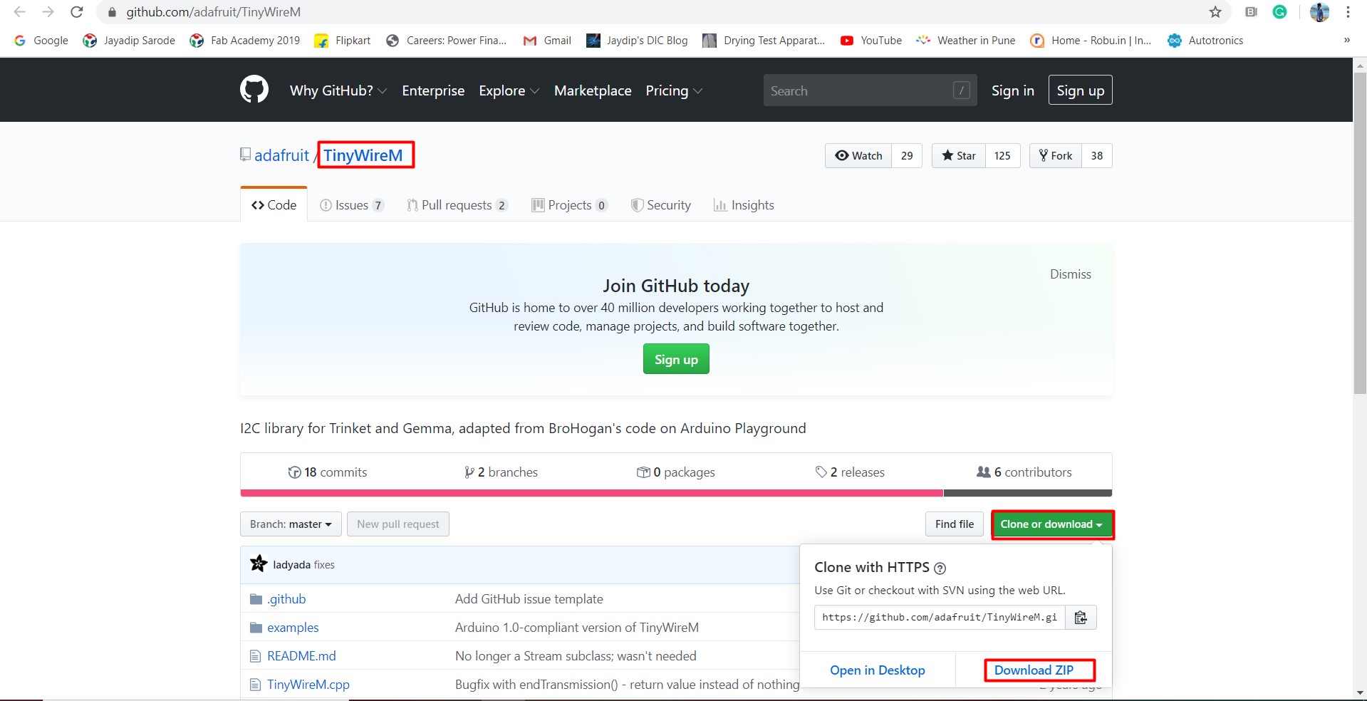
So, I have to download a 'TinywireM' library for I2C communication. I downloaded this library from githum.com and I also attached link here, so you can download 'TinywireM' library
While I'm uploading code to my 'Master board' of networking, I see following error:
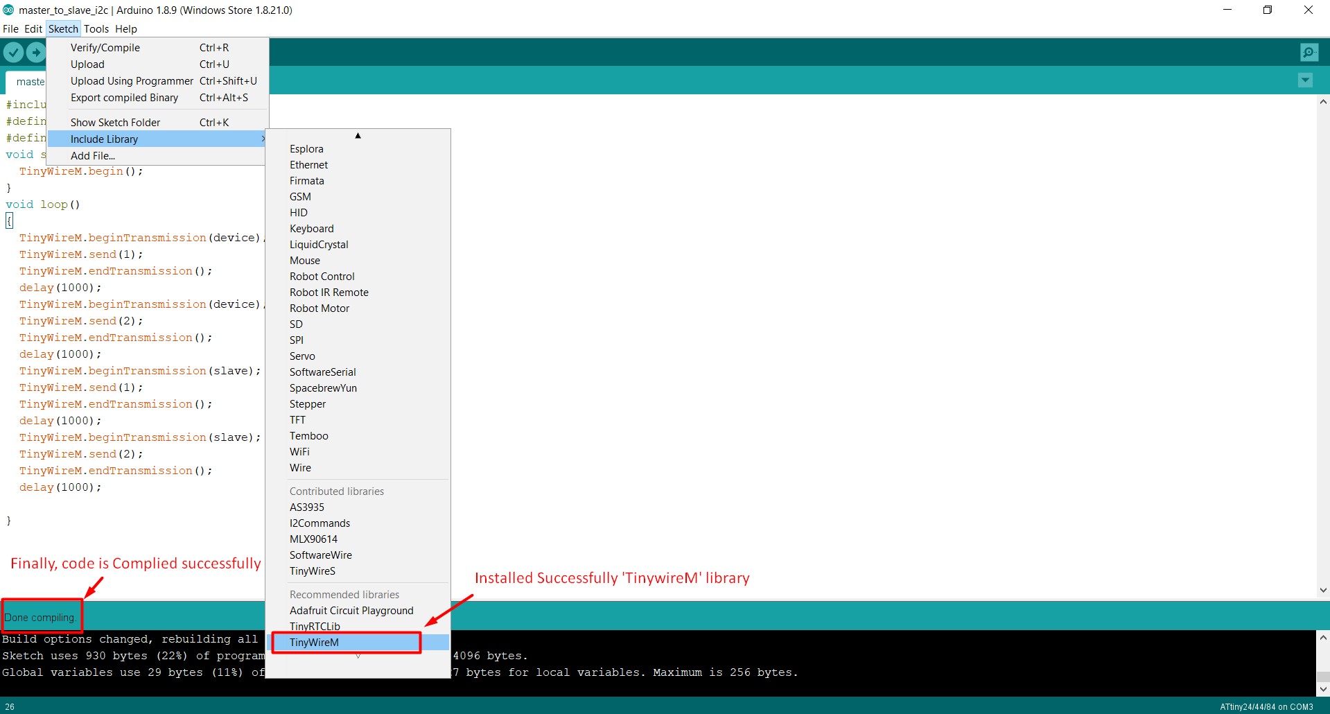
Here inside the code, I defined two different slave IDs to be detected by the micro-controller with specific ID.They will communicate each other by a definite time delay. This is the code for master board controller.
#include#define device (1) #define slave (2) void setup() { TinyWireM.begin(); } void loop() { TinyWireM.beginTransmission(device); TinyWireM.send(1); TinyWireM.endTransmission(); delay(1000); TinyWireM.beginTransmission(device); TinyWireM.send(2); TinyWireM.endTransmission(); delay(1000); TinyWireM.beginTransmission(slave); TinyWireM.send(1); TinyWireM.endTransmission(); delay(1000); TinyWireM.beginTransmission(slave); TinyWireM.send(2); TinyWireM.endTransmission(); delay(1000); }
Code for "slave-1" :
This is the code for "slave-1" ID for define it, I place i2c node 1 as a "slave-1" id.
#includeint output=PA7; // LED connected to PA7 pin of attiny 44 #define I2C_SLAVE_ADDR (1) // 1 is the address of Node 1 void setup() { // put your setup code here, to run once: TinyWireS.begin(I2C_SLAVE_ADDR); pinMode(output, OUTPUT); } volatile byte msg = 0; void loop() { if (TinyWireS.available()) msg = TinyWireS.receive(); if (msg == 1) digitalWrite(output, HIGH); else if (msg == 2) digitalWrite(output, LOW); else msg = 0; }
Code for "slave-2" :
This is the code for "slave-2" ID for define it, I place i2c node 2 as a "slave-2" id.
#includeint output=PA7; // LED connected to PA7 pin of attiny 44 #define I2C_SLAVE_ADDR (2) // 2 is the address of Node 2 void setup() { // put your setup code here, to run once: TinyWireS.begin(I2C_SLAVE_ADDR); pinMode(output, OUTPUT); } volatile byte msg = 0; void loop() { if (TinyWireS.available()) msg = TinyWireS.receive(); if (msg == 2) digitalWrite(output, HIGH); else if (msg == 1) digitalWrite(output, LOW); else msg = 0; }
I2C communication between Master and Slaves:
Learning Outcomes:
1. Learned how to do communication between two boards and interfacing between them.
2. Understood various types of Serial, Parallel communications protocol.