ATtiny (also known as TinyAVR) are a subfamily of
the popular 8-bit AVR microcontrollers, which typically has fewer
features, fewer I/O pins, and less memory than other AVR series chips.
The first set of series were released in 1999 by ATMEL, later acquired
by Microchip in 2016. This data is taken from ATMEL.

Prof. Neil was mentioning about Charlieplexing and Multiplexing during
the session this week.

Charlieplexing is a technique for driving a multiplexed display in which
relatively few I/O pins on a microcontroller are used e.g. to drive an
array of LEDs. The method uses the tri-state logic capabilities of
microcontrollers in order to gain efficiency over traditional
multiplexing.

Multiplexing (or muxing) is a way of sending multiple signals or streams
of information over a communications link at the same time in the form
of a single, complex signal; the receiver recovers the separate signals,
a process called demultiplexing (or demuxing). Bitwise Operations is an
operator used to perform bitwise operations on bit patterns or binary
numerals that involve the manipulation of individual bits, similar to
logic operators.

I went through these diagrams for getting an idea about this week’s
assignment. In this picture it shows ATTiny 85 is controlling the
temperature. When the temperature goes down, the fan turns off. When the
temperature goes high, the fan turns on. So I have used the same
principle. But to control the fan, I am using a Relay Module 12v to
control the fan to be used in my final project, Smart FAB air cooler.
Ideation – My Mind Mapping
 Relay Module –
 A relay is an electrically operated
switch that can be turned on or off, letting the current go through or
not, and can be controlled with low voltages, like the 5V provided by
the Arduino pins. I have used this One Channel Relay Module to control a
12v DC Fan in my final project.
 Testing Video - Assignment
12 Output Device_files\input output devices.AVI
PCB
Testing Video - Assignment
12 Output Device_files\input output devices.AVI
PCBI have milled and soldered a new pcb for the Input
and Output Assignment as shown below.
 PCB Milling Video – https://youtu.be/ua7fWLVYzR4
Design file –
 Assignment 12 Output Device_files\in and
out.brd
Code-
int sensorPin = PB4;
int ledPin1 = PB3;
//int ledPin2 = 4;
int sensorValue = 0;
float volts=0.0,temp=0.0;
void setup() {
pinMode(ledPin1, OUTPUT);
//pinMode(ledPin2, OUTPUT);
//Serial.begin(9600);
}
void loop() {
sensorValue = analogRead(sensorPin);
volts= sensorValue*5.0/1023;
temp = volts*100;
//Serial.print("Temprature is");
//Serial.print(temp);
if(temp > 30) {
digitalWrite(ledPin1,HIGH);
//digitalWrite(ledPin2,LOW);
}
else {
//digitalWrite(ledPin2,HIGH);
digitalWrite(ledPin1,LOW);
}
delay(100);
}
My code for this assignment shows that when the temperature goes up, the
LED turns off and when the temperature is medium the LED turns on.
Video Link
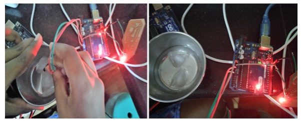
 Group Assignment –
 I have teamed up with Jaydip for
this group assignment.

I have used this PCB for testing as I did have a through hole component.
The LED is off as the temperature is cold.
Learning Outcome – I learnt how to put output on the
pcb. The difficulty faced was rendering the blue tooth module to my pcb.
Reference – FAB Academy Tutorials, Internet and
Wikipedia
http://fab.cba.mit.edu/classes/863.09/people/ryan/week5/ATtiny44%20Data%20Sheet.pdf
http://fab.cba.mit.edu/classes/863.17/CBA/people/annawb/week9.html
http://archive.fabacademy.org/2018/labs/fablabcept/students/rutuja-patel/13-output-devices.html
https://bigladdersoftware.com/epx/docs/8-3/input-output-reference/group-fans.html#inputs


